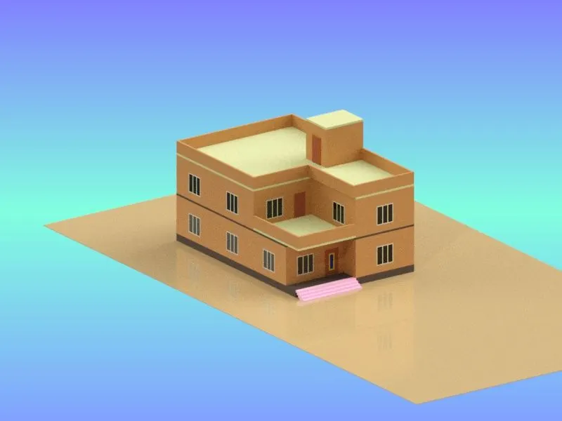
Project 2_Creating a 3D rendered model for a Residential Building in AutoCad
Project 2:Creating a 3D rendered model for a Residential Building in AutoCad.
AIM: To create the 3D rendered model for a residential Building in AutoCAD.
INTRODUCTION: The 3D View of wall Spread footing is created in AutoCAD in 3D modelling workspace using primarily the line and Extrude tools.The procedure of drawing is explained and final result is given.
PROCEDURE:
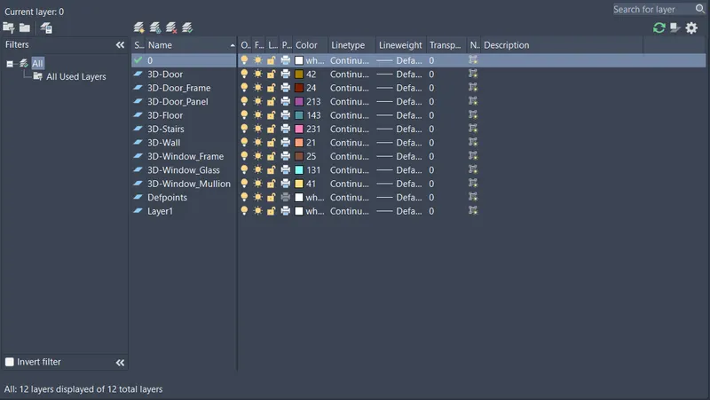
Layer Properties
Architectural drawing:
a) Plan:
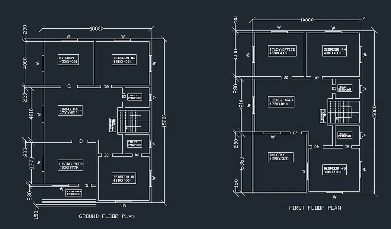
- Give the Size of the plot using the rectangle command and offset for the thickness of the wall.
- Give the orientation of the plot by making the east direction.
- Now draw the ground floor plan.
- Using the offset command draw the bedroom of size 4.81x4m.
- Then for the toilet offset 1.8m in the vertical direction and 2.2m in horizontal direction.
- For the kitchen offset 4m in the vertical direction and 4.5m in horizontal direction.
- Now draw the stairs from north of the dining room and 1m offset for the width of the stairs.
- Stair dimension thread-0.25m and riser-0.16m and width-1m.
- Draw 5 steps in the first flight offseting 0.25m and draw a landing of 1m width.
- For the next 3rd flight steps again offset 0.25m.
- Now draw the dining room by offsetting 4.81m in the horizontal direction and 4.73m in the vertical direction.
- Now insert the text using multiline text with text height as 0.10m style as standard.
- Now we draw the first floor plan:
- Copy the ground floor plan and we make few changes.
- The kitchen is replaced with Study room.
- And the Dining hall replaced with Lounge area and the Living and Verandah is replaced with Balcony.
- Now we create the doors and windows and making them as a blocks.
- Assume door size as:D1-1.2x2m and D2-1mx2m, D3-0.8mx2m.
- Place the door wherever opening is provided and mark them as D1,D2 and D3.
- Assume the size of the windows as W-1.5x1.5m and ventilator as V-0.6x0.6m.
- Place the windows and Ventilators in required position.
- Mark them as W,V and make them in block.
- Now insert the dimensions using the DLI command.
- Now create the layer using layer properties.
- Assign different colour to each layer in order to distinguish it.
- Insert respective elements in the layer.
- Insert the steps infront of the entrance with riser 0.15m and thread as 0.3m.
b) ELEVATION:
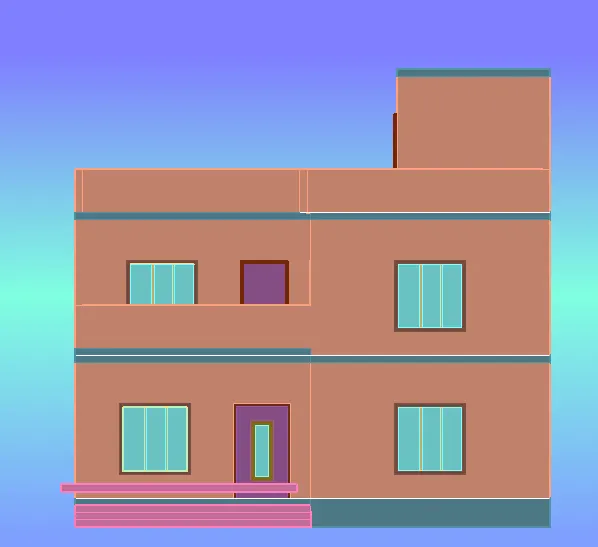
- Now project the lines to draw the elevation.
- Project the wall line to the top and draw a horizontal line.
- Offset 0.4m for the plinth level and 3m for the first floor level and 3m again for the second floor level.
- we draw the doors and windows from the plan and give heights of 2m and 1m as required.
- Project the shades and draw the shades at top of the window level.
- Trom off extra lines using the trim command.
- Offset 0.076m for the thicknessof doors and windows.
- Copy the windows and doors to another side also and draw the sunshade also.
- project 1m to top to show the parapet wall.
Constructing the 3D Model:
- Create the plinth level by using region and boundary.
- Create the wall by extruding it.
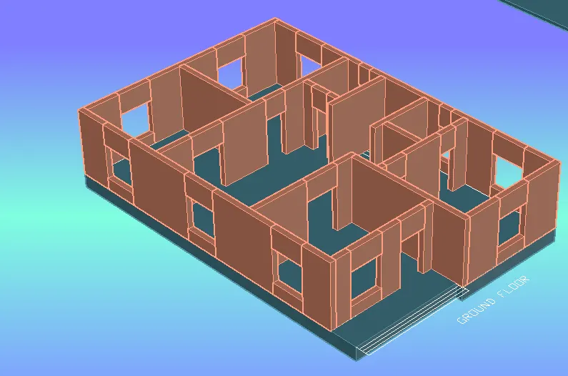
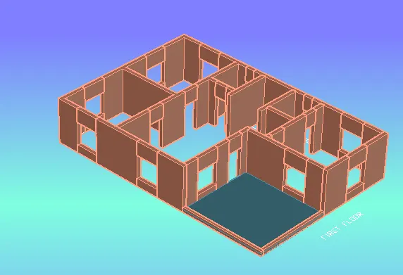
- Create the window and door and place them.
- Placing walls, doors, and windows together.
- Create the chajja.
- Place the ceiling over the ground floor.
- Create the same as thet is created in the ground to the first floor.
- Create the celing of the first floor and create the parapet wall.
- Create the stairs for the front door.
- Show the top and front views of the building.
- Image after assigning the materials to the different components.
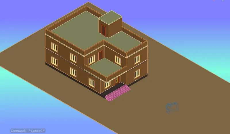
RESULT: Rendered View of Duplex Model.