Project 2_Creating a 3D rendered model for a Residential Building in AutoCad
Name: Allan Bryan Jayson Cruz
Course: Master’s Certification Program in High-Rise Building Design & Analysis
Date: December 6, 2021
Project 2_ Creating a 3D rendered model for a Residential Building in AutoCAD
********************************************************
1. Aim & Introduction
***************
Aim
This challenge aims to let the student utilize the tools in AutoCAD to create a 3D sketch. It aims to help the student familiarize with the different 3D commands present in the AutoCAD software. It also provides the student the experience to create a 3D model rendered from 2D sketch until the final model.
Introduction
The AutoCAD software provides different tools. The tools used in this challenge is as described below:
Line - creates line object.
Polyline - creates connected line object.
Rectangle - creates rectangle object.
Circle - create circle object.
Trim - Cut unwanted lines or shapes with the provided cutting edges.
Extend - Extend lines to opposite corners.
Move - Move objects to particular locations.
Copy - Copy objects to particular locations.
Rotate - Rotate selected objects to a particular angle with respect to base point.
Array - Copy an object in a set path linearly or polarly.
Join – Joins separated line objects into one object. Line to polyline.
Dimlinear (DLI) - Provides vertical or horizontal linear/straight dimensions.
Dimaligned (DAL) - Provides aligned dimensions.
Dimangular (DAN) – Provides angular dimensions.
Quickdimension (QDIM) – Provides quick dimension of a geometry.
Leader - Creates an arrowhead line.
Layers - Provide identification of line or object groups by their properties.
Units - Open "Drawing Units" window to specify the drawings units.
Dimstyle - Open "Dimension Style Manager" window to modify the dimension properties.
Hatch - Provides hatching pattern in each object or internal point.
Layer - Open the layer tab which manages the line properties in a drawing.
********************************************************
2. Sketch and Procedure
***************
A. Create a 3-dimensional model of the residential building with a rendered view.
PROCEDURE:
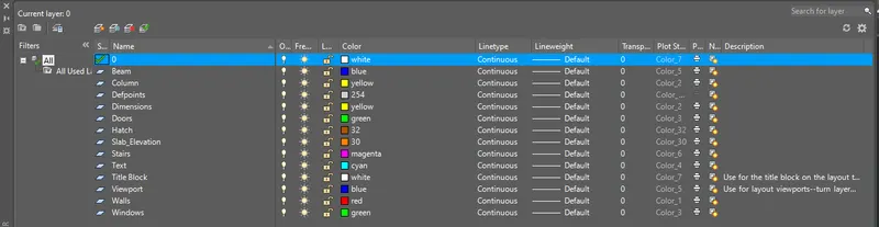
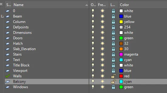
--> Decide the layers.
- These layers can be adjusted later as per requirement. Use the layer command.
--> Proceed with the plan drawing.
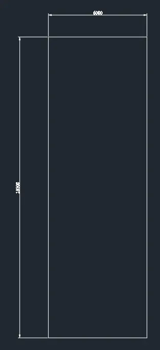
- Create boundary using rectangle object. Dimension 6m by 18.3m.
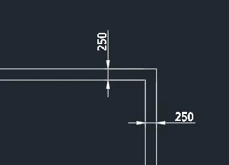
- Offset it by 250 towards the inside to project the wall. Add the plant north facing east.
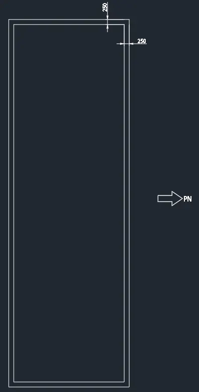
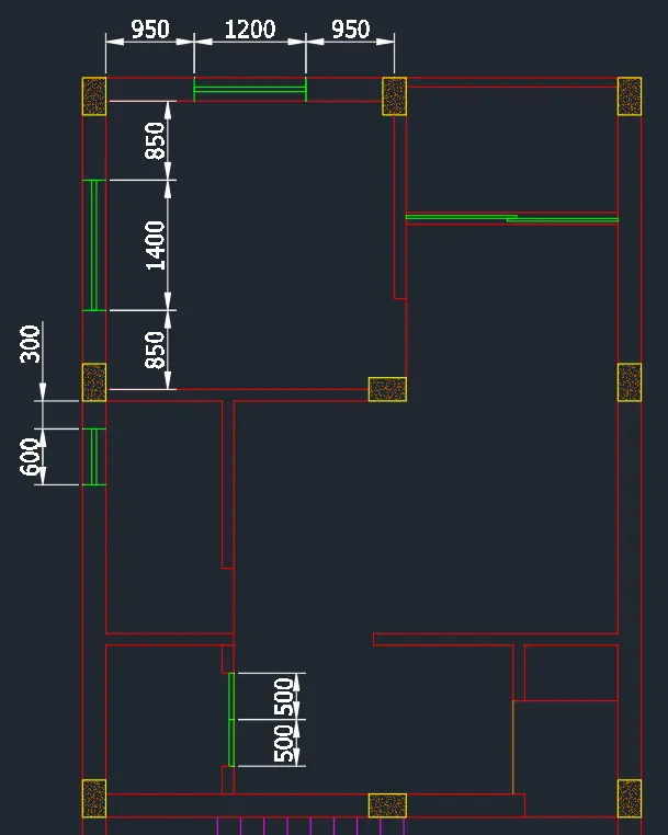
- Now create a projected boundaries for the layout. Add lines and use the extend/trim command to sketch the plan.
- Start from the top, position stairs in the middle.
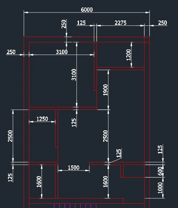
- Use line and trim tool to add the wall openings and trim the unnecessary lines.
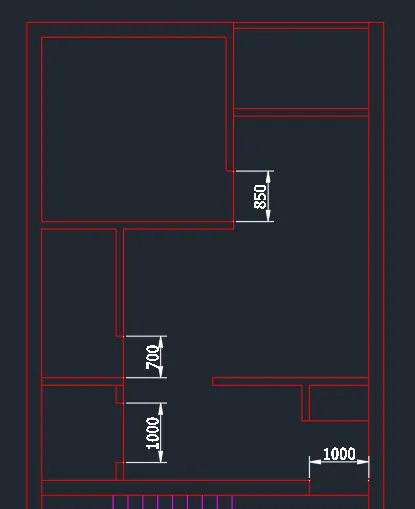
- Add the columns. Column size is 250x400mm
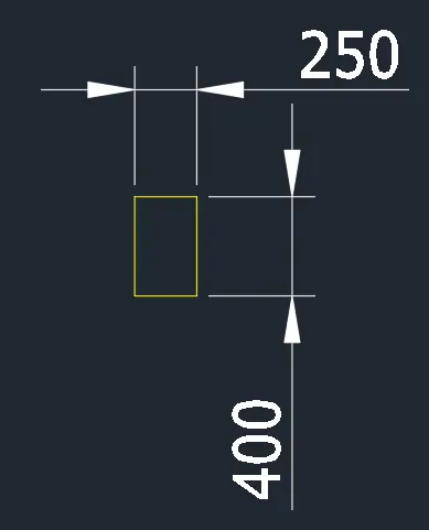
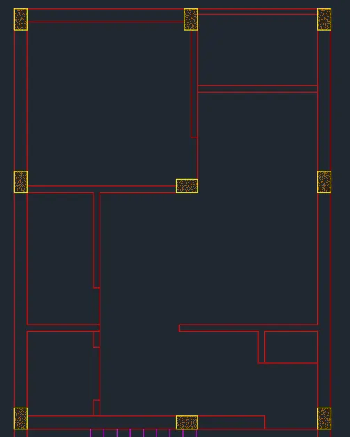
- Add the doors and windows at locations where it is needed.
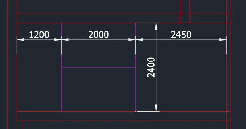
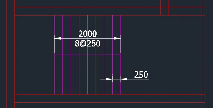
- Create the stair provision at the middle part.
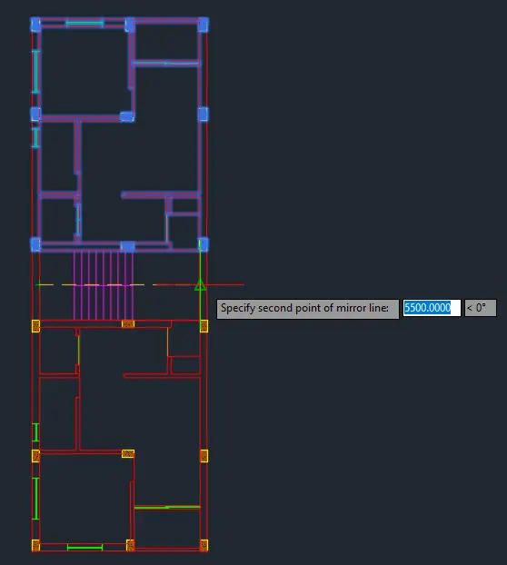
- Mirror the layout of the top room and mirror it on the other side. Include the columns, walls, windows and doors to the other side.
- Add the door symbol.
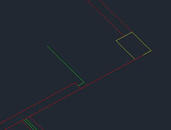
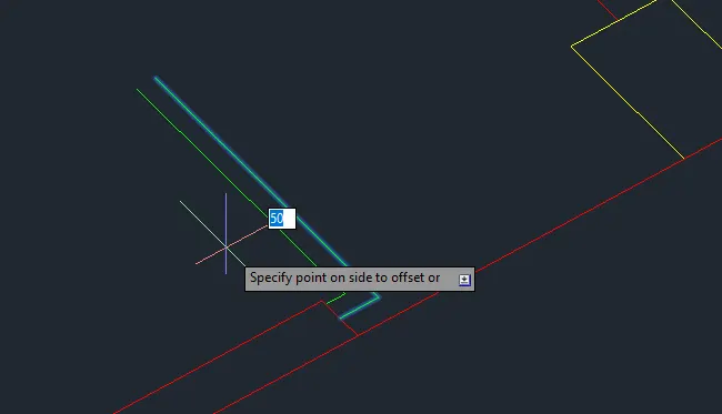
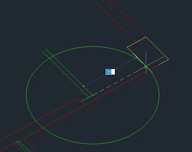
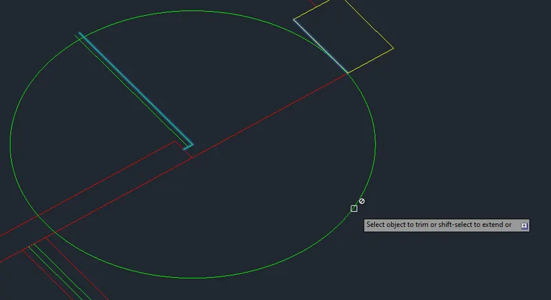
- Trim and close the edges.
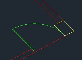
- Copy the door symbol to other doors.
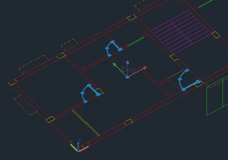
- Mirror to the other side.

- Turn the plan into a group.
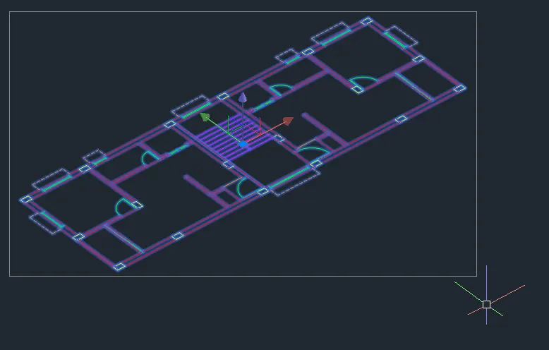
--> Create the Front and Side Elevation of the Drawing in the Front View.
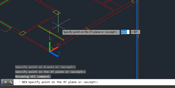
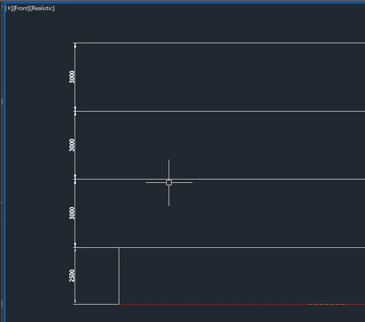
- Add the window and door locations.
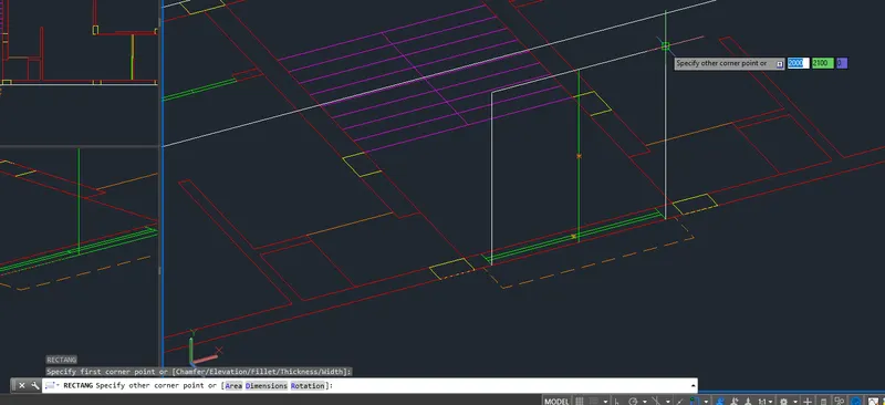
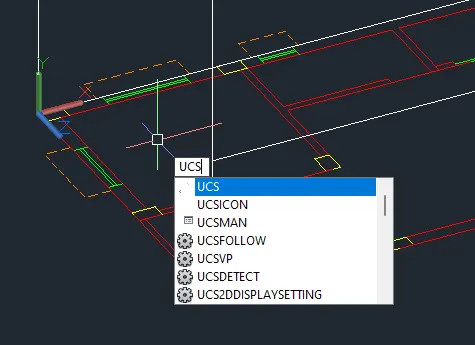
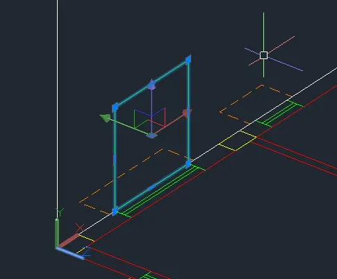
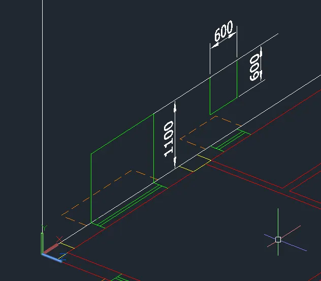
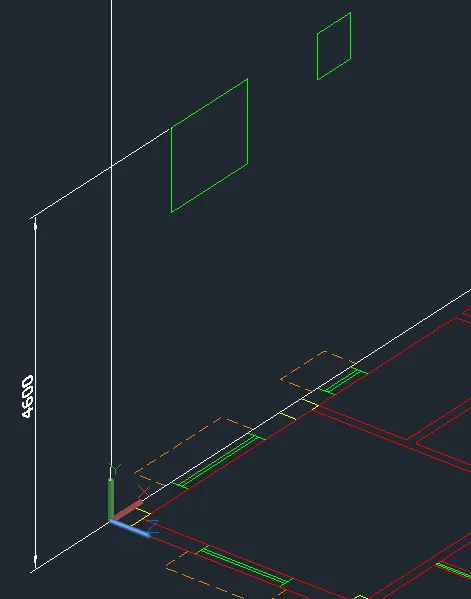
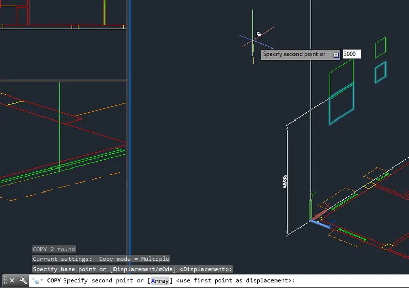
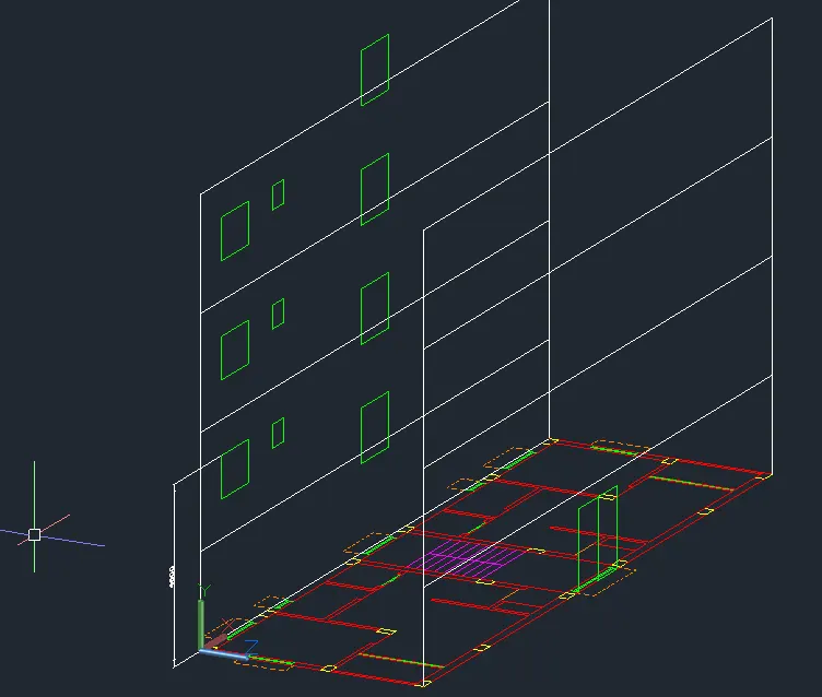
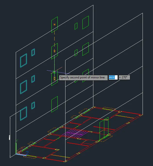
--> Proceed to extrusion of columns. Move elevation to the second floor.
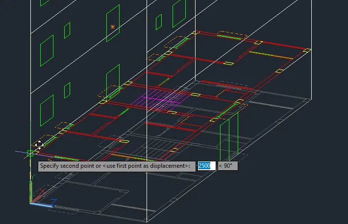
- Turn off the other layers to avoid selecting them.
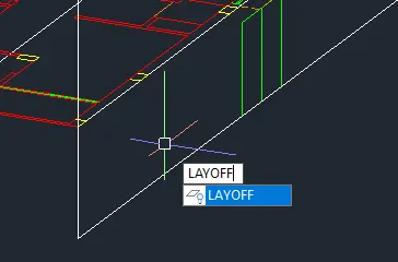
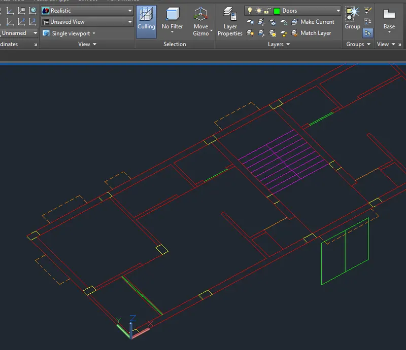
- Extrude The Columns. Isolate the column layer to avoid selecting the others.
- Move the columns to the bottom.
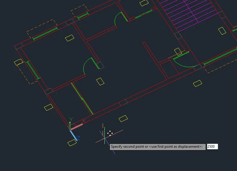
- Extrude to the structure height.
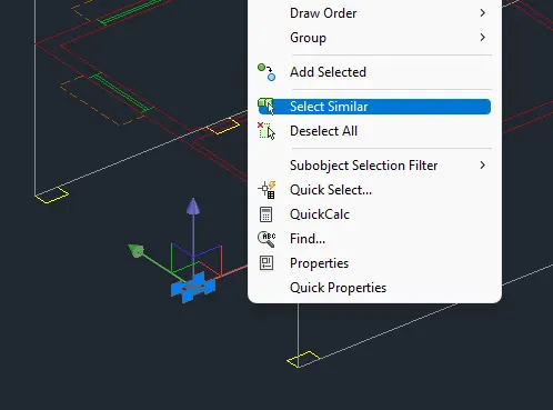
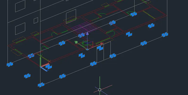
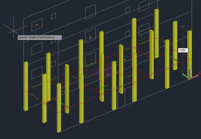
- Turn on all the laures and proceed with the walls on the 2nd floor.
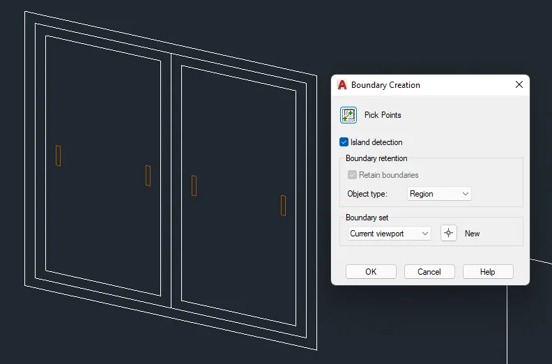
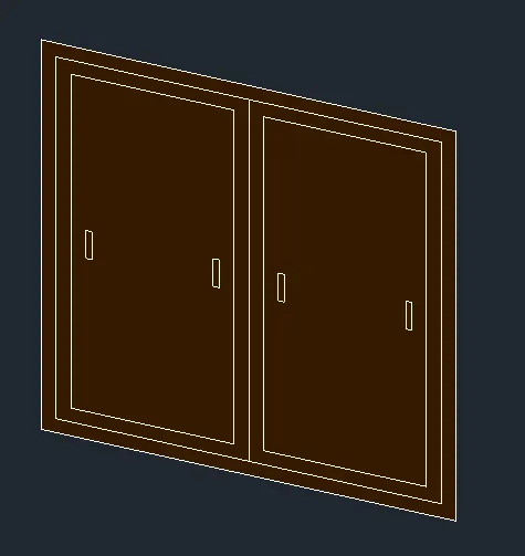
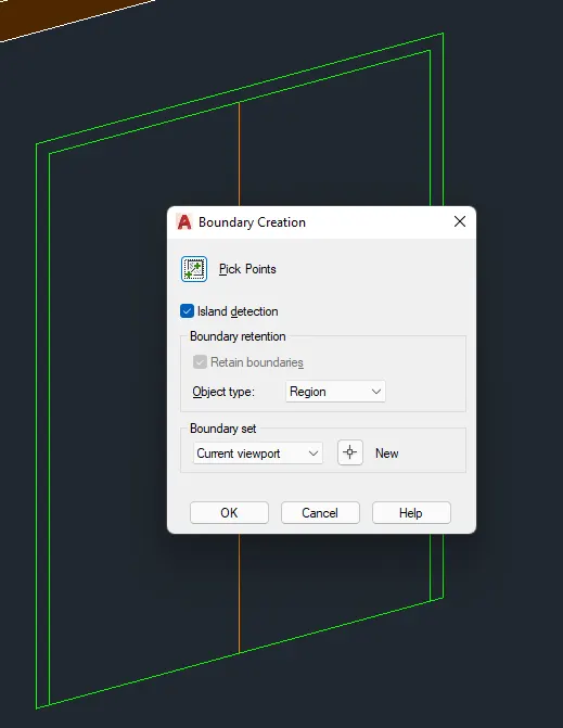
- Create regions for extrusion.
- Turn off unnecessary layers.
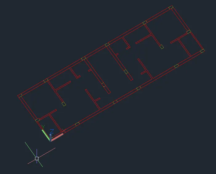
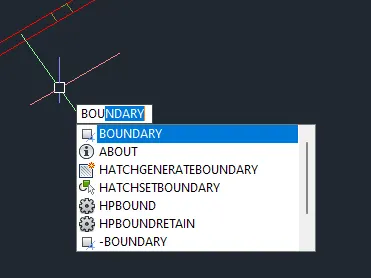
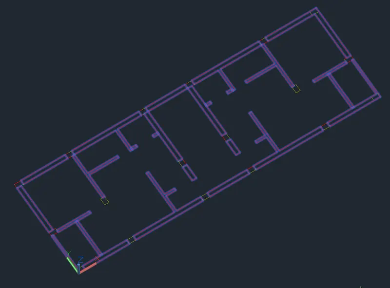
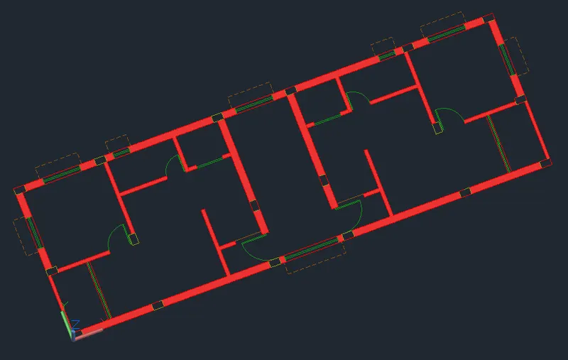
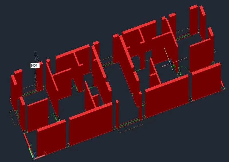
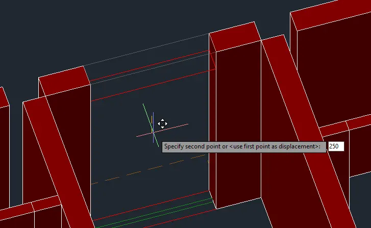
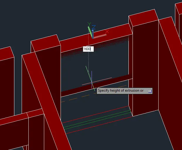
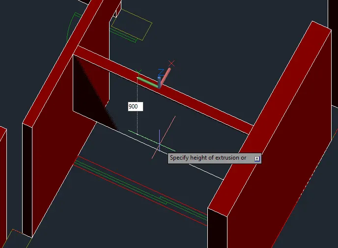
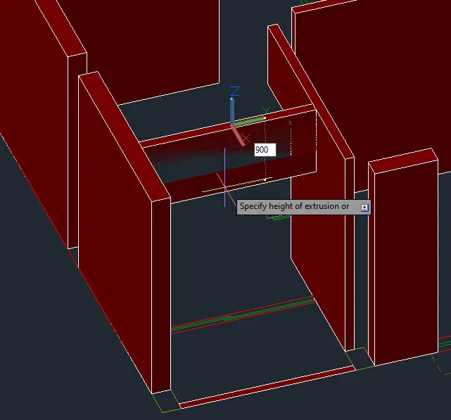
- Create the opening.
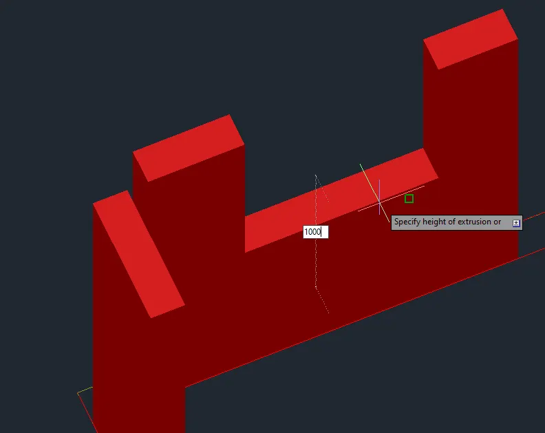
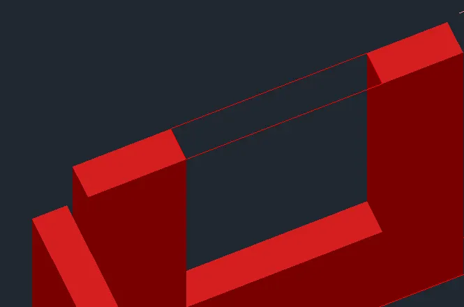
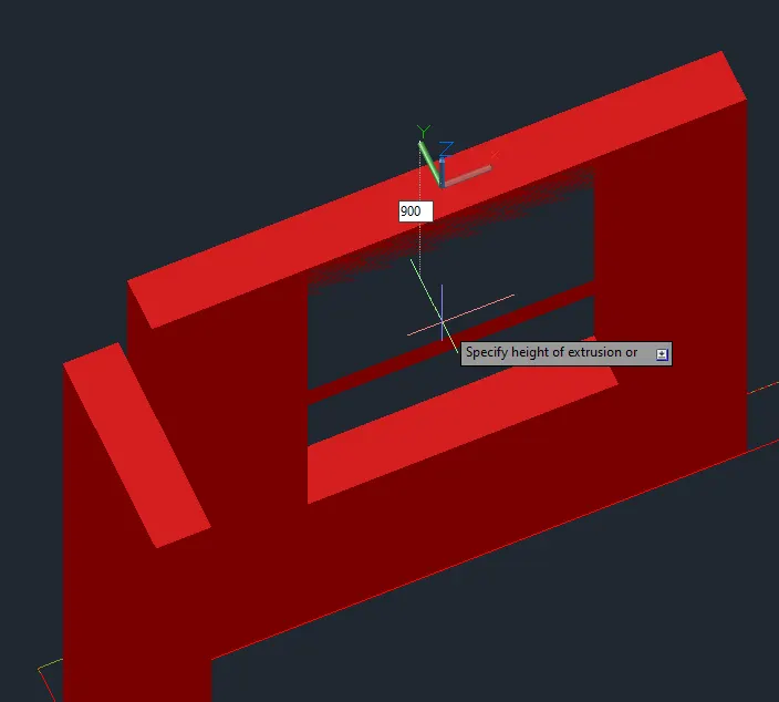
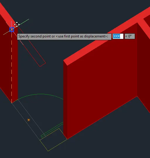
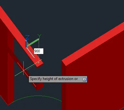
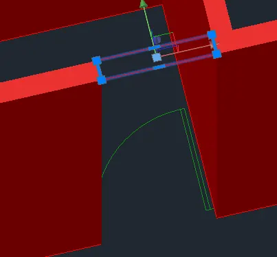
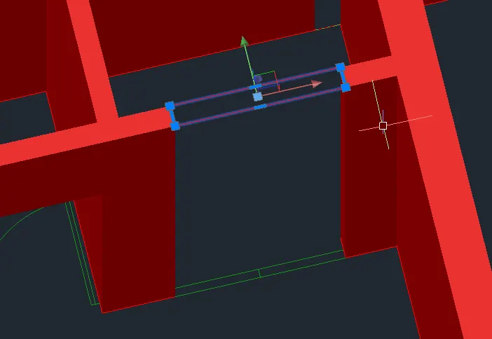
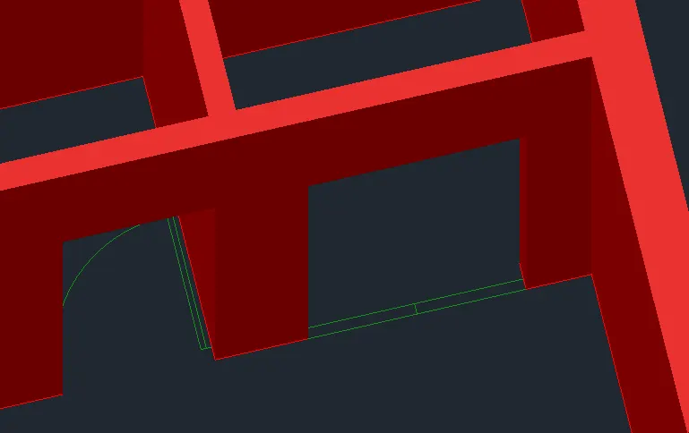
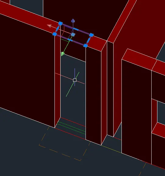
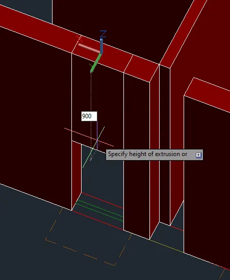
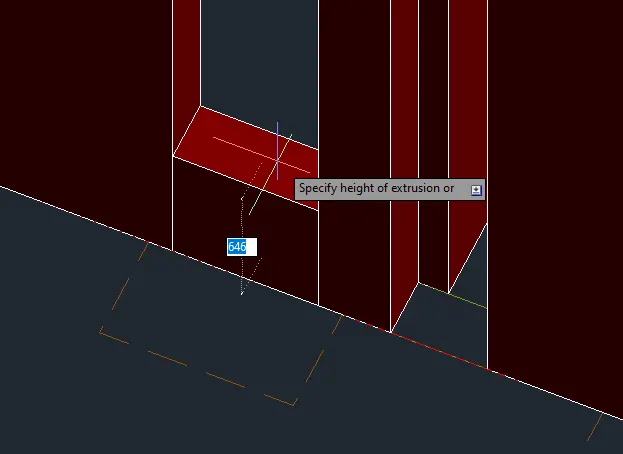
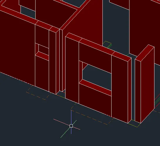
- Copy the opening edges to the other side. Mirror is also applicable.
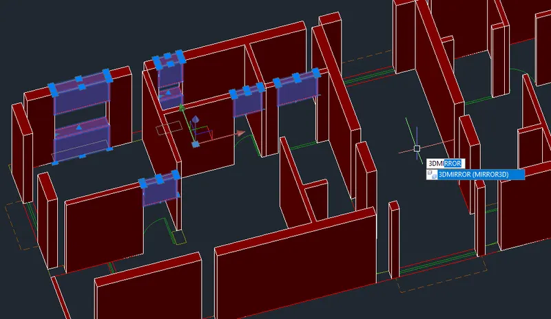
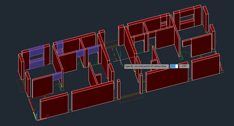
- Create the opening for the stair.
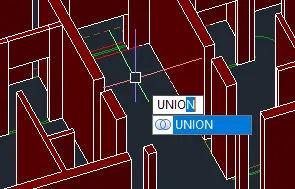
- Join the 3d solids using union.
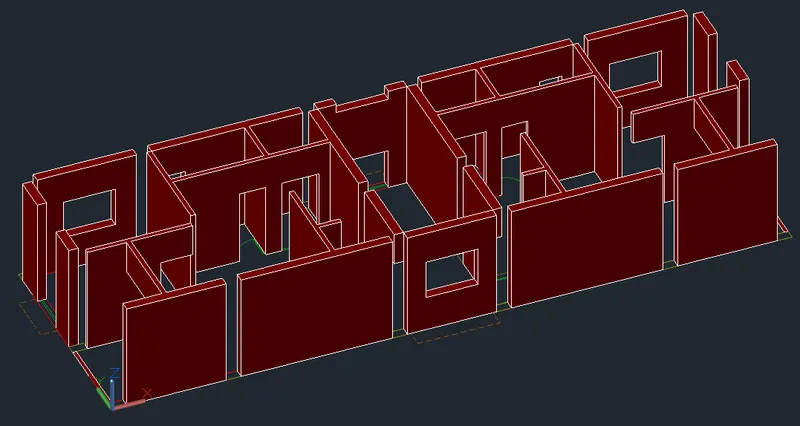
- Proceed with the balcony.
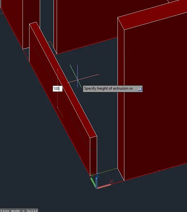
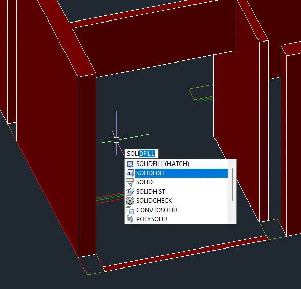
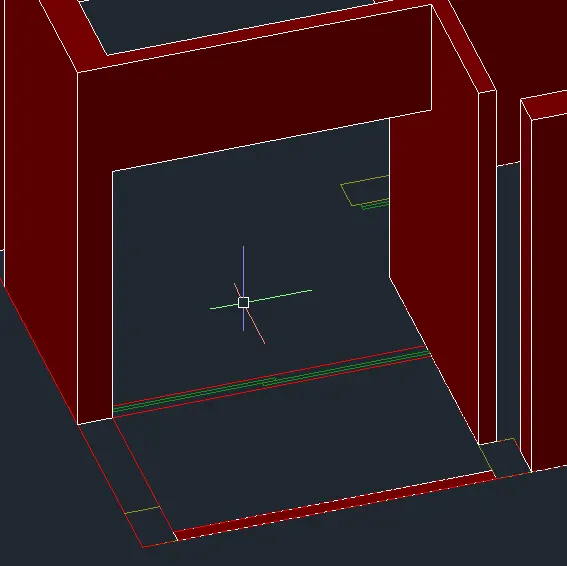
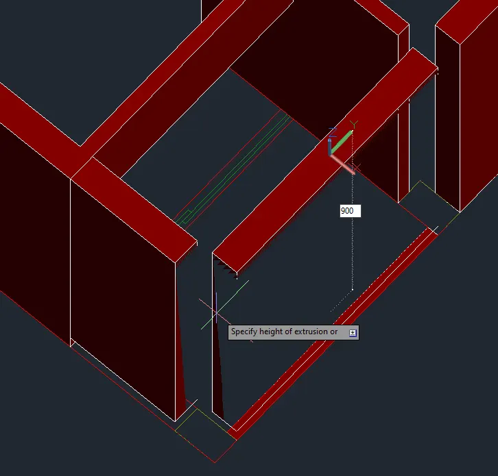
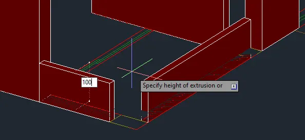
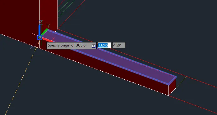
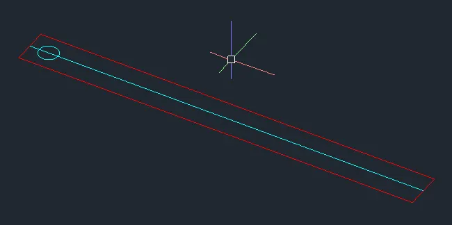
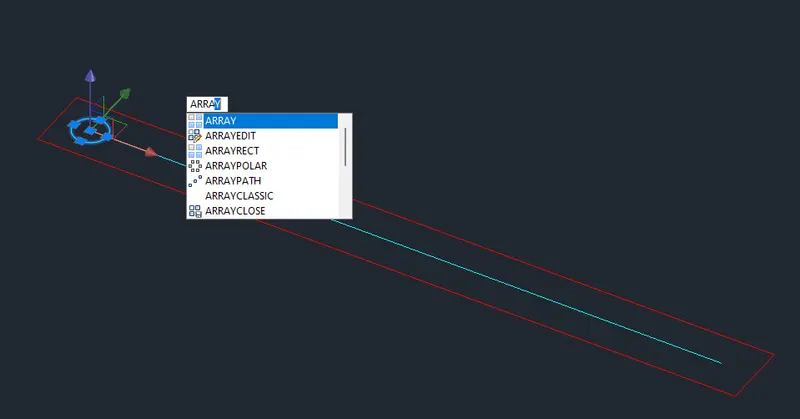
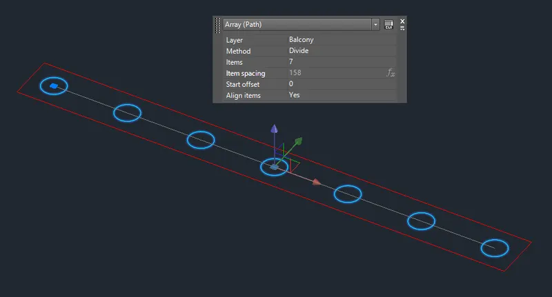
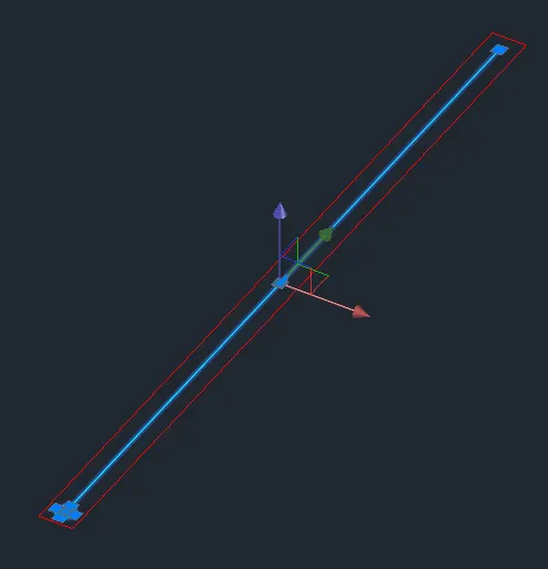
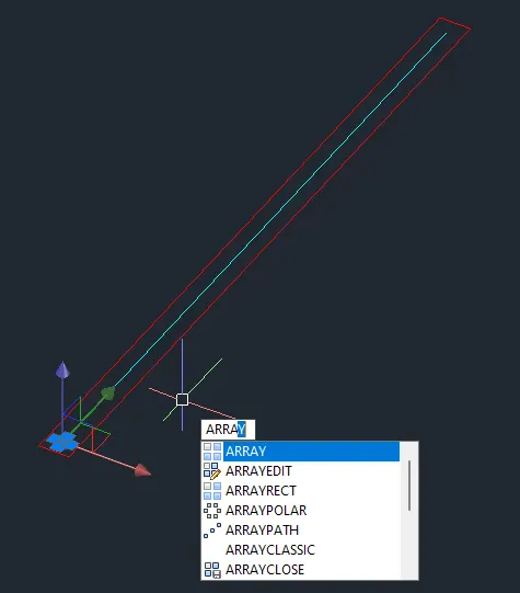
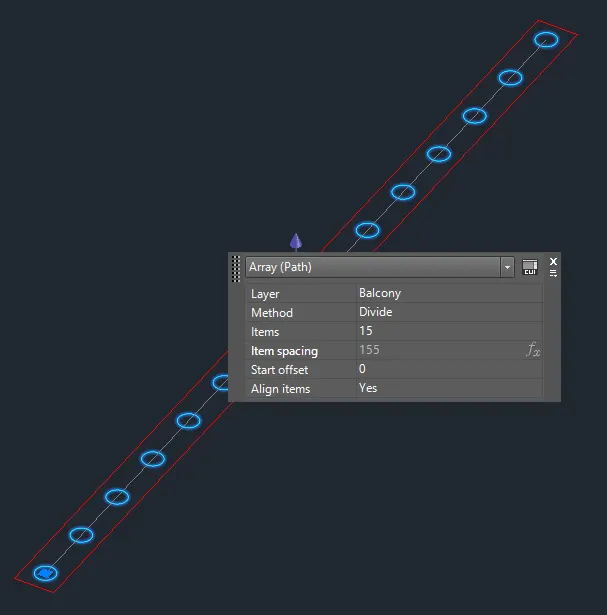
- Explode the array for extrusion.
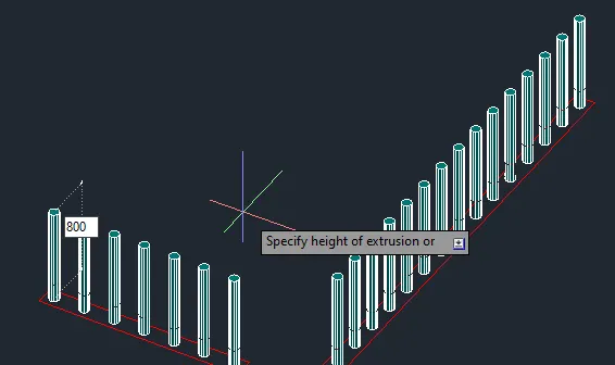
- Add the line on top.
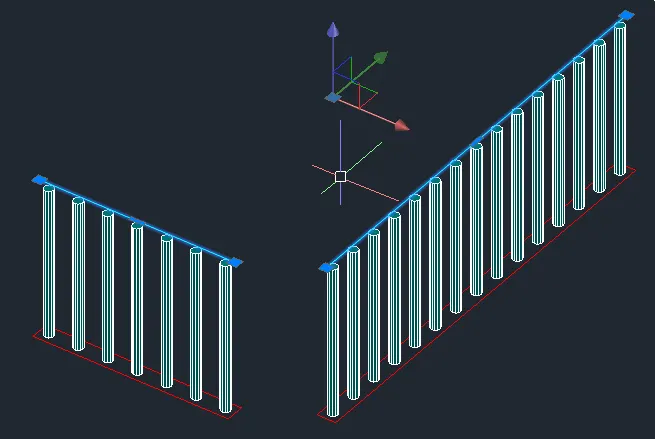
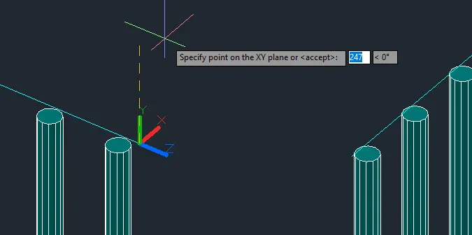
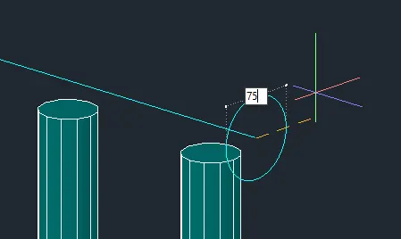
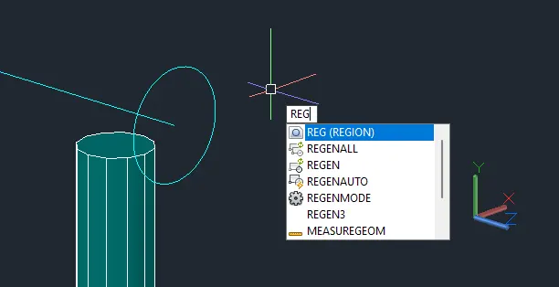
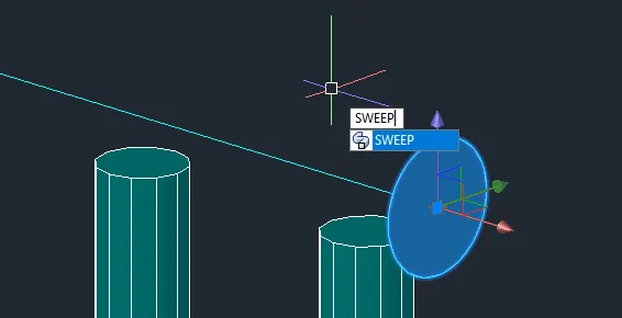
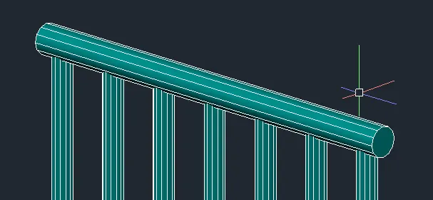
- Do the same on the other side.
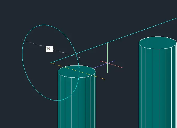
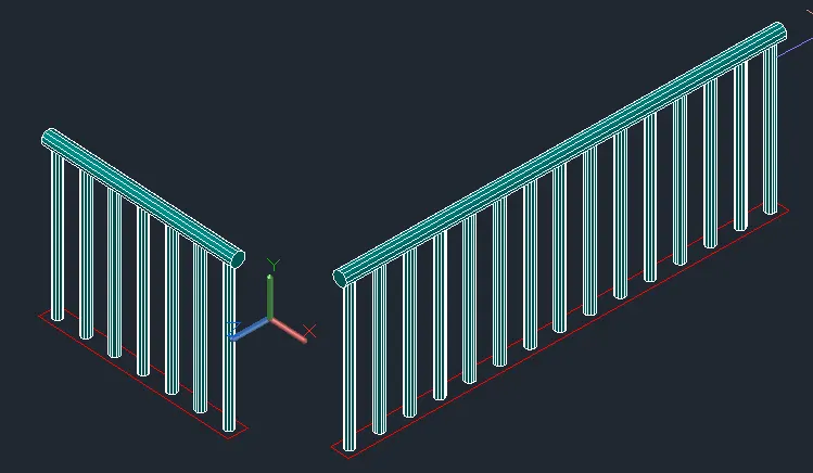
- Mirror to the other side of the building.
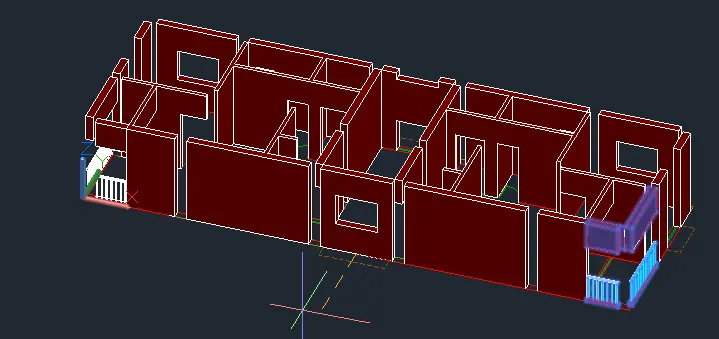
- Add the slabs.
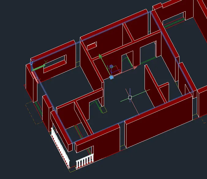
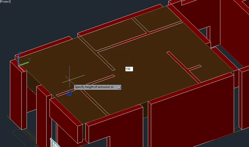
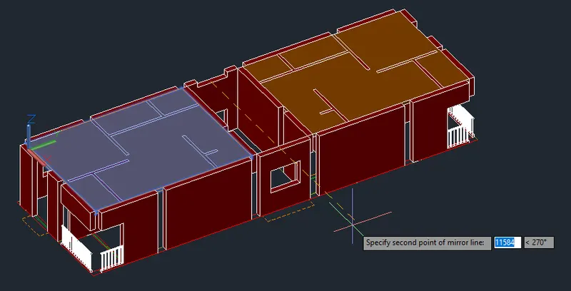
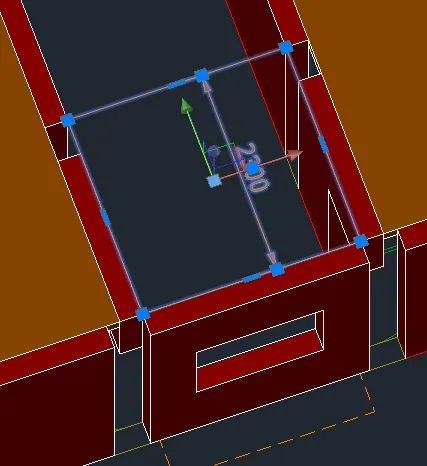
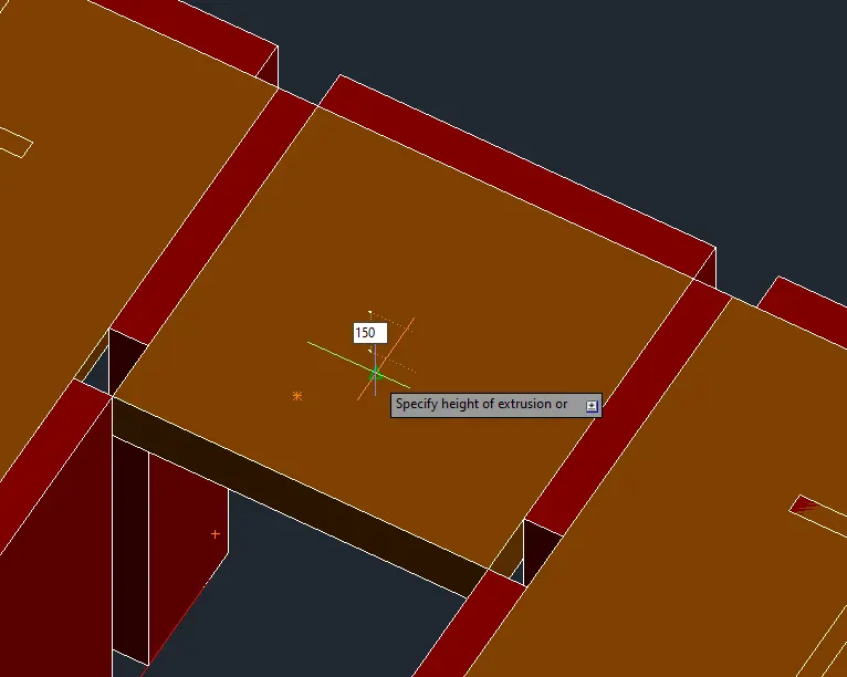
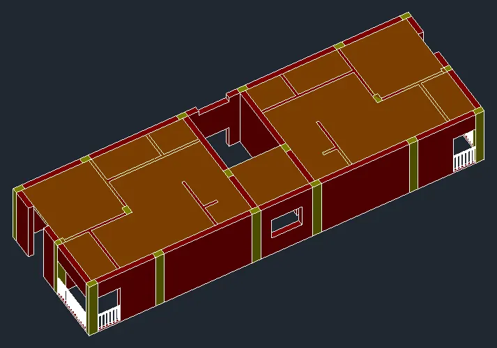
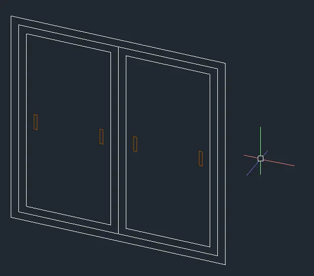
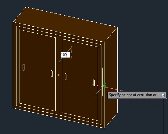
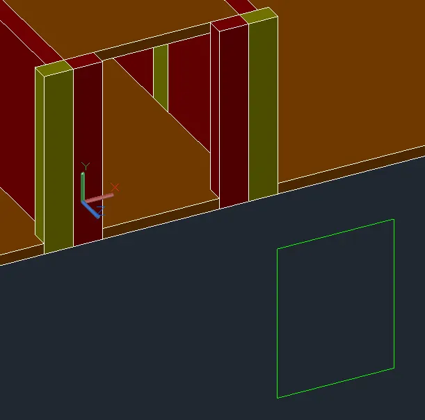
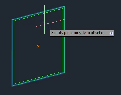
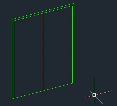
- Create the Door and Window Faces.
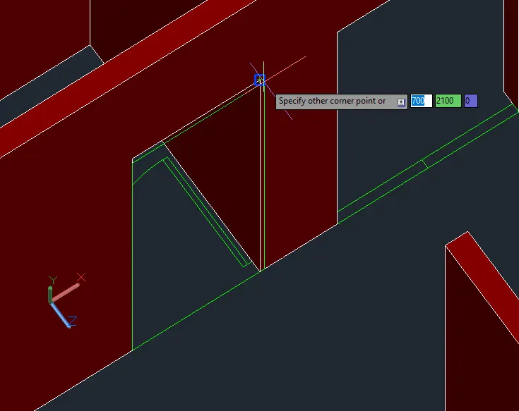
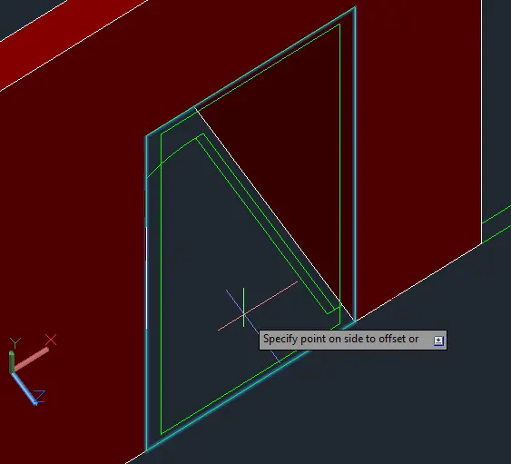
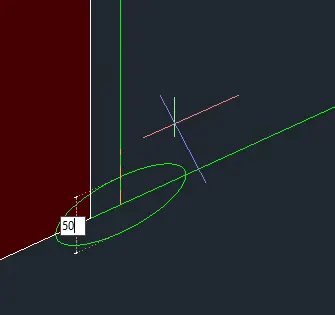
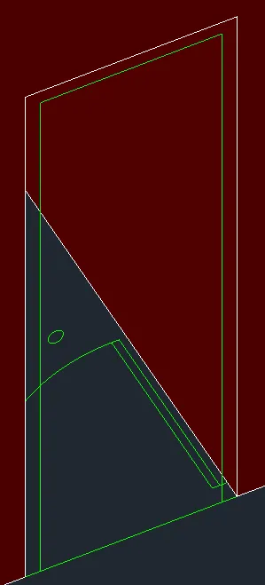
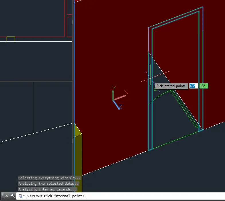
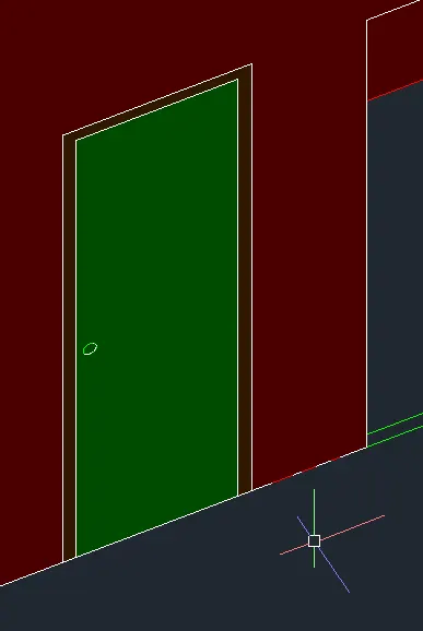
- Extrude for solidity.
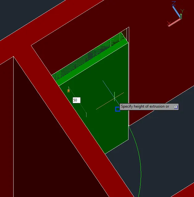

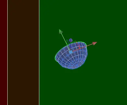
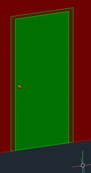
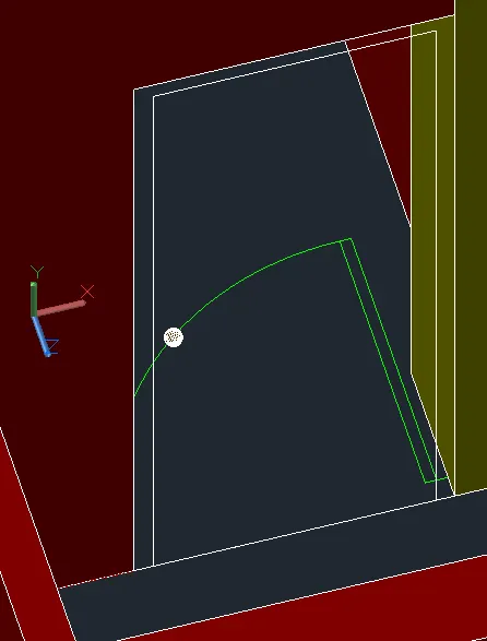
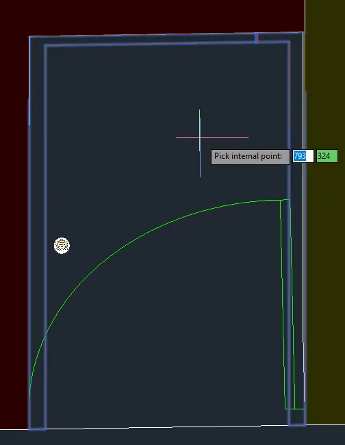
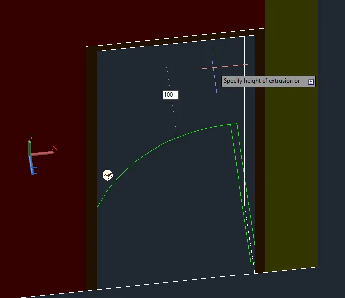
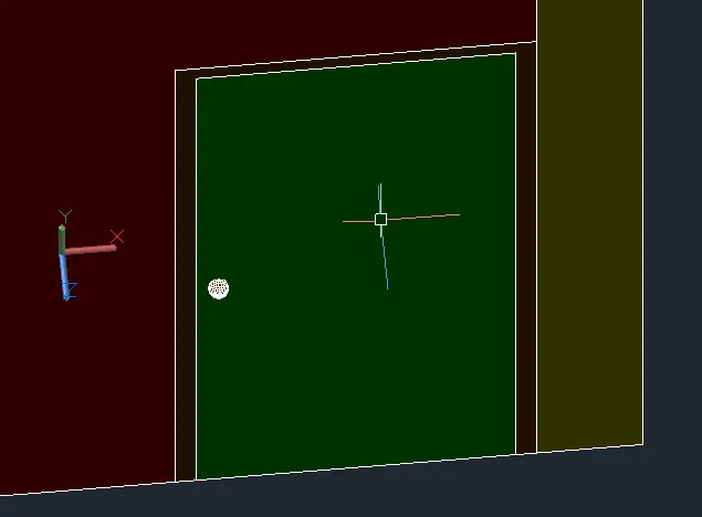
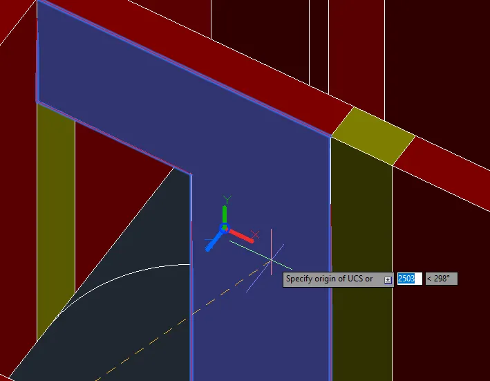
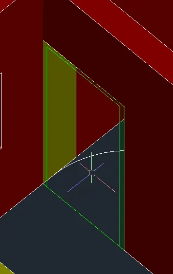
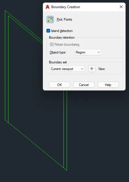
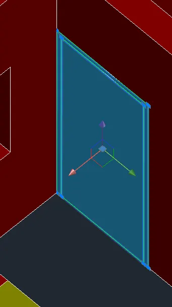
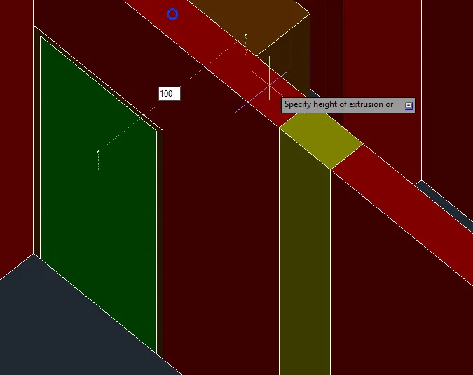
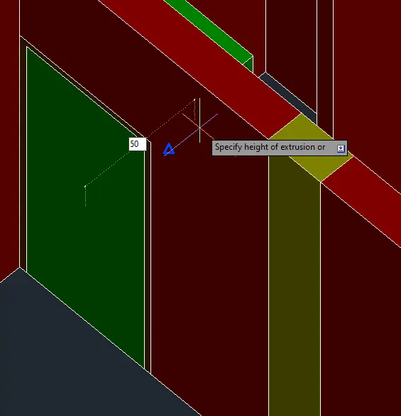
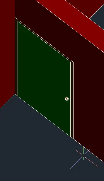
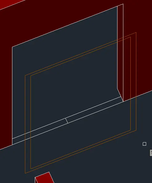
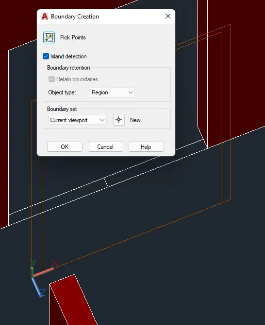
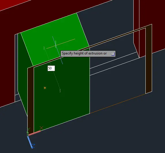
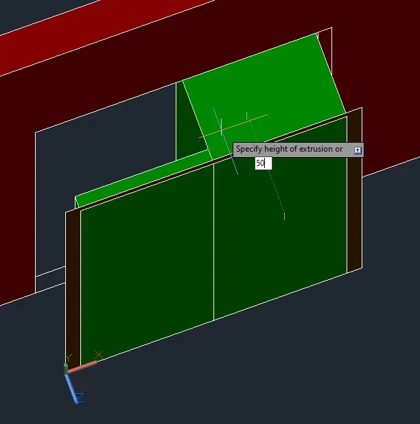
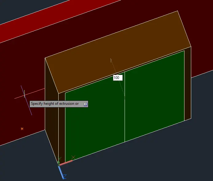
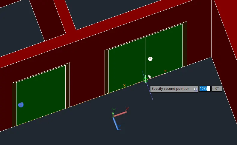
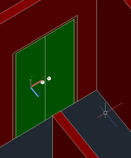
- Mirror to the other side.
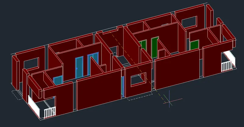
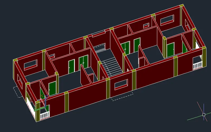
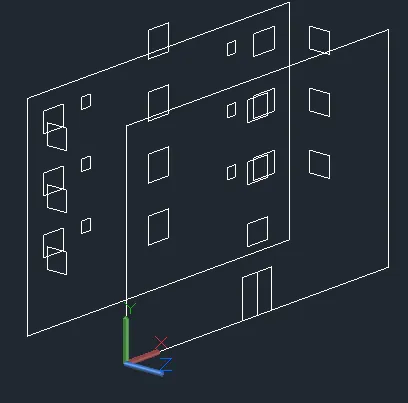
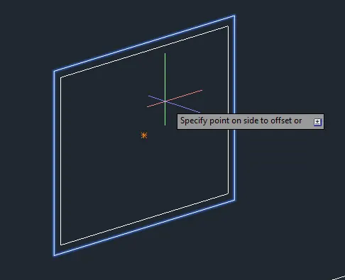
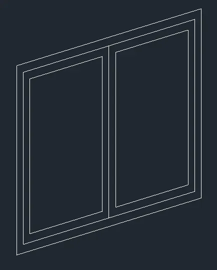
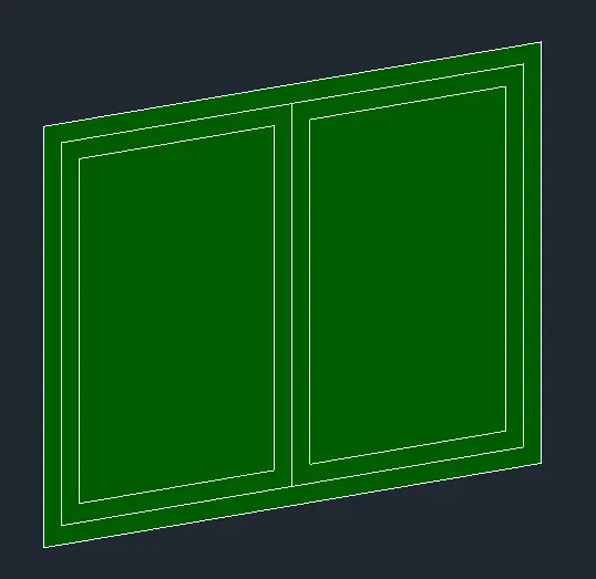
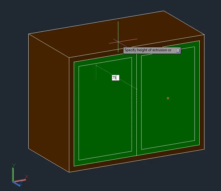
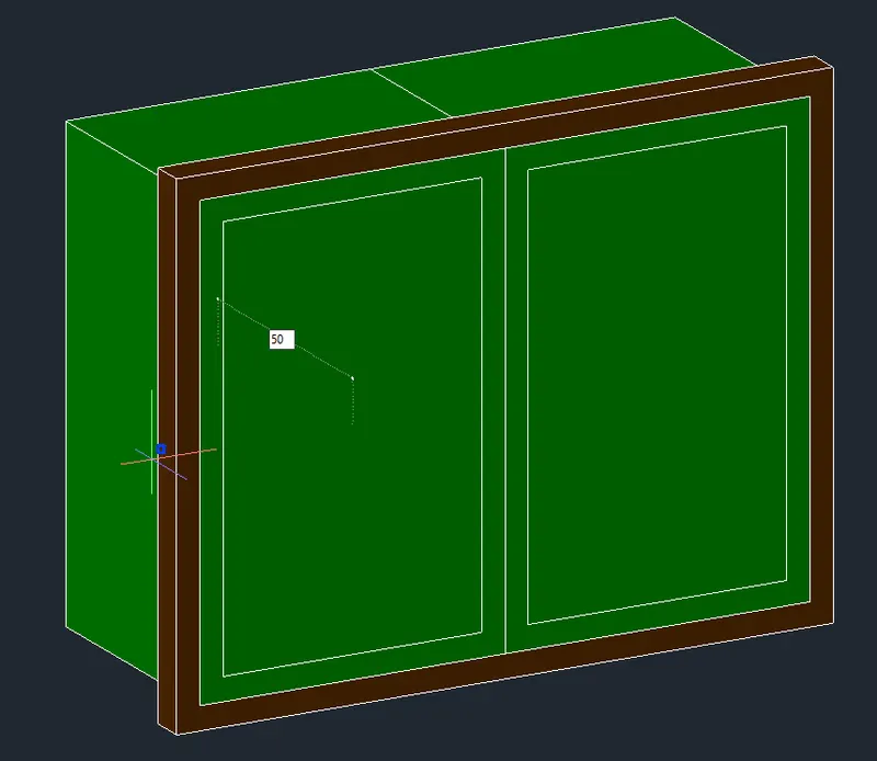
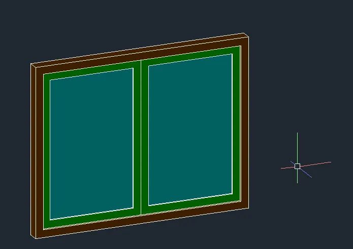
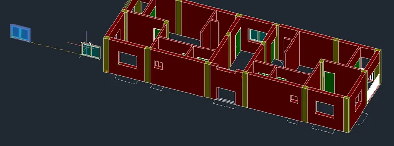
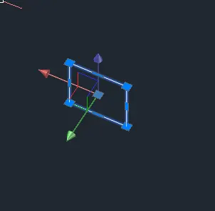
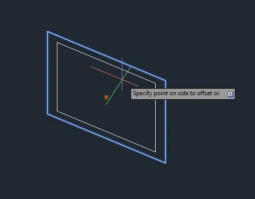
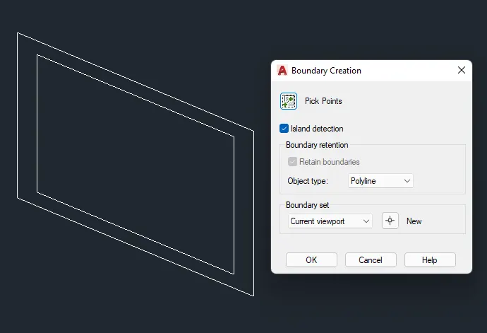
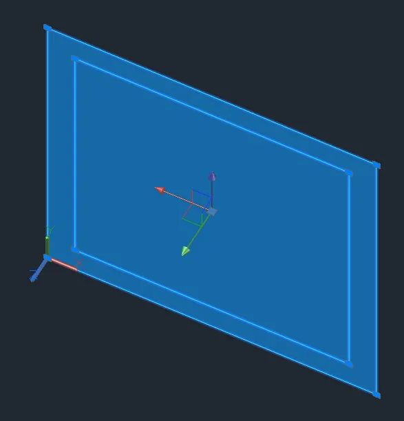
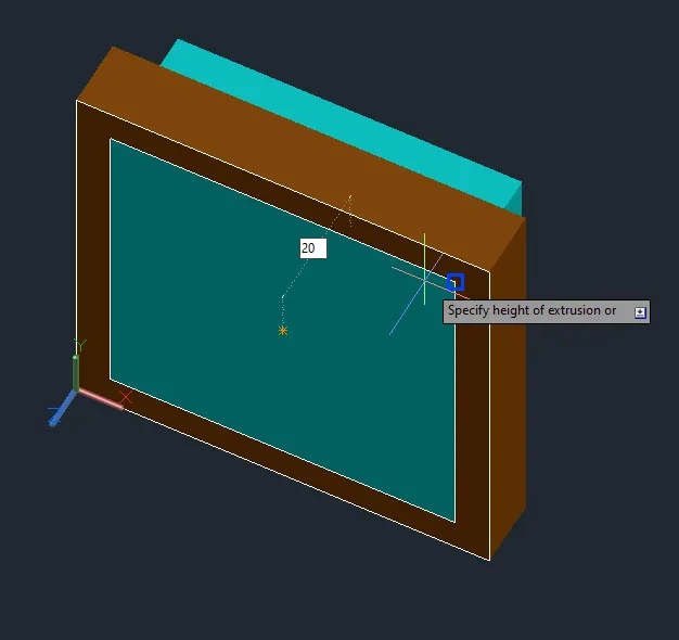
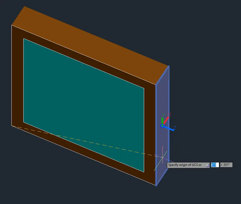
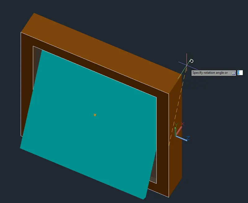
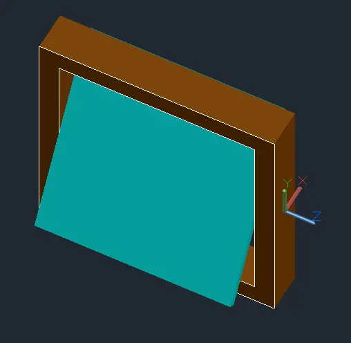
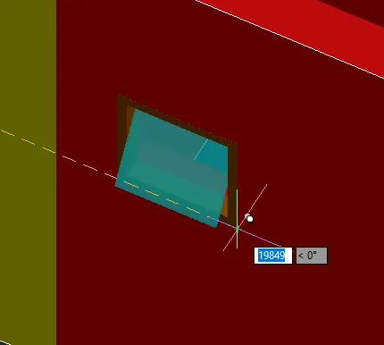
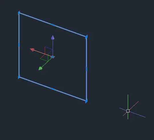
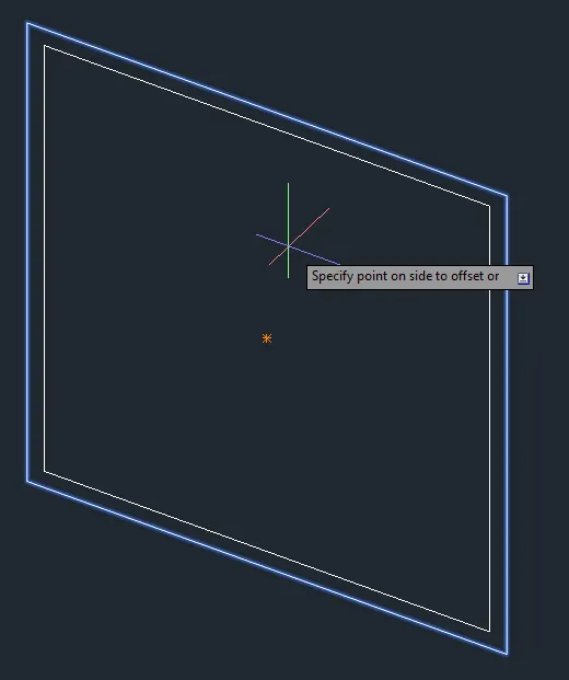
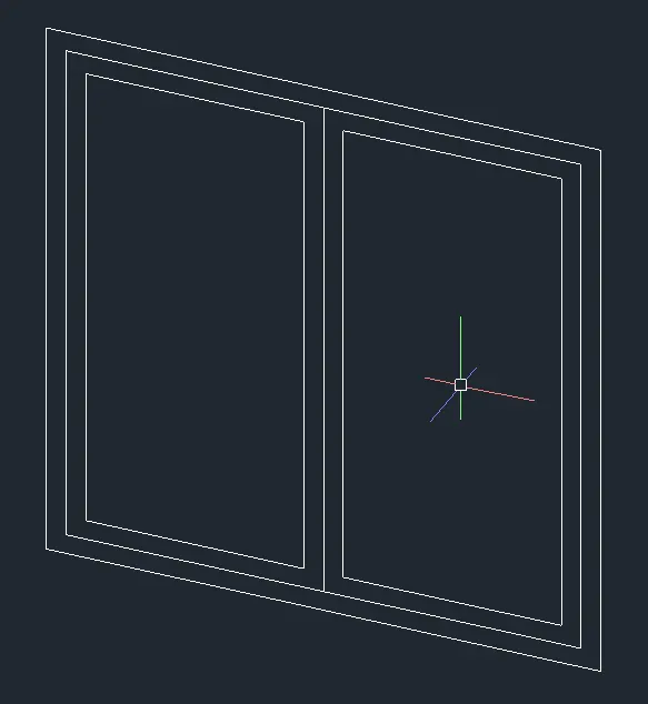
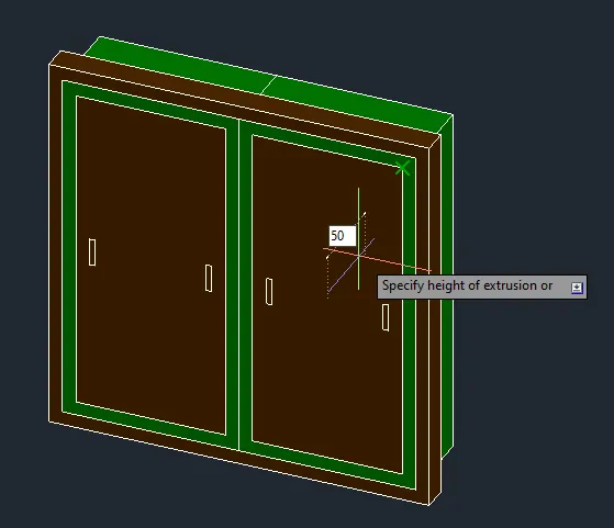
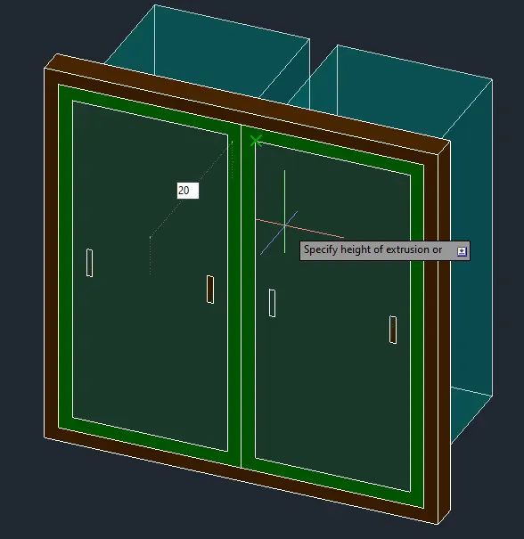
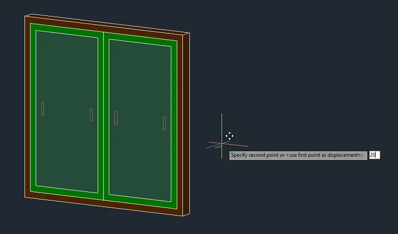
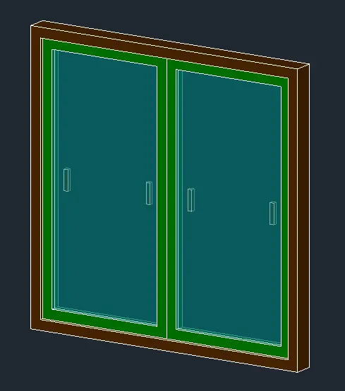
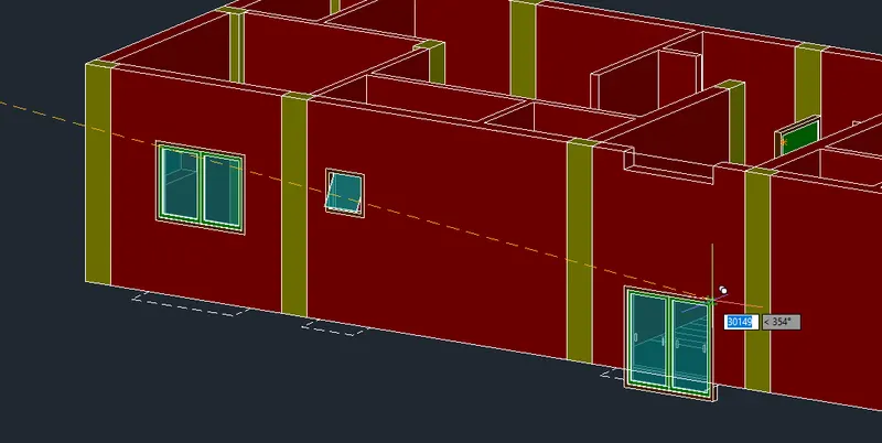
- Once the first floor is done, copy it to duplicate the floors.
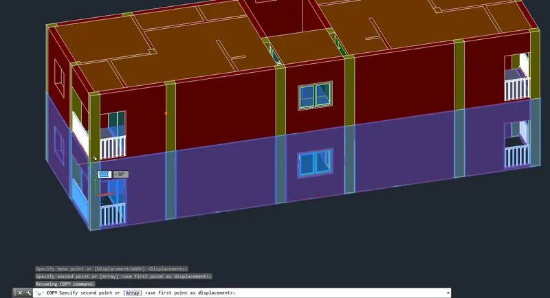
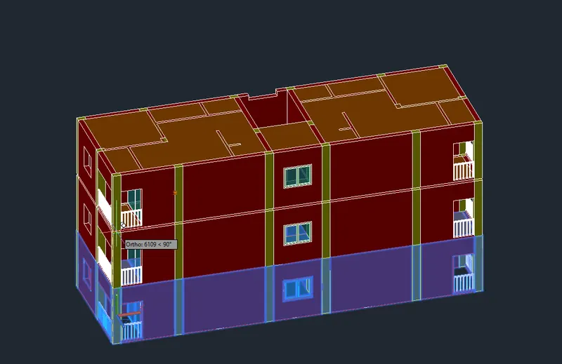
- Create the Balcony.
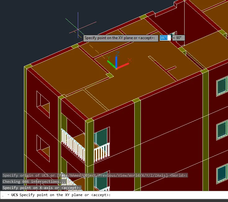
- Separate the line for better view.
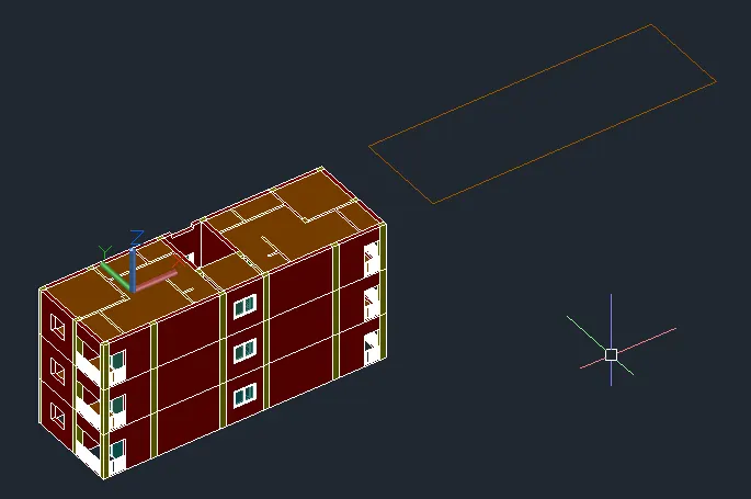
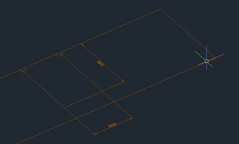
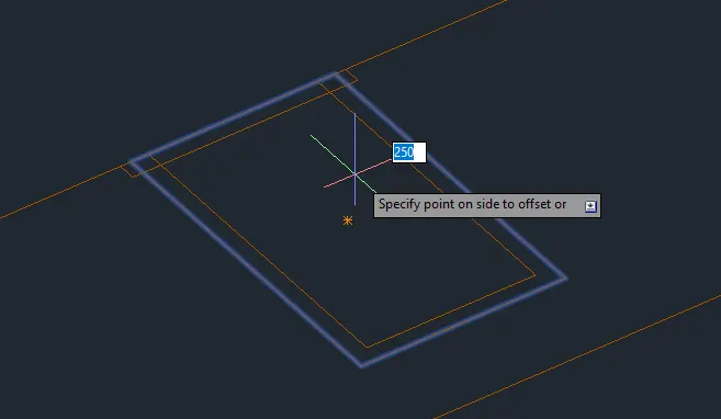
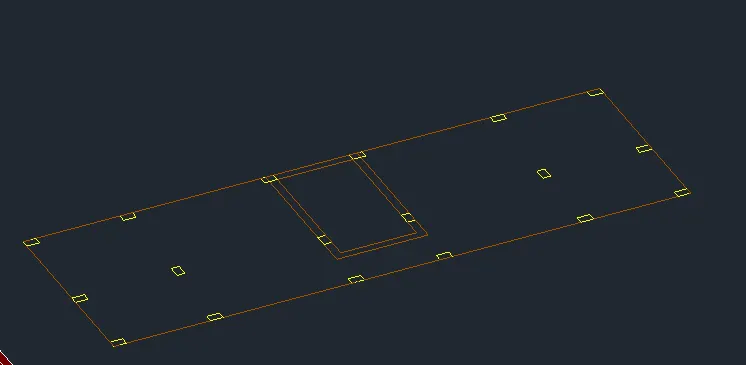
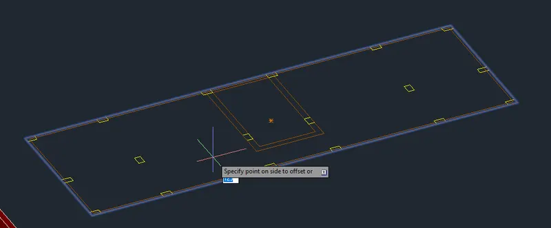
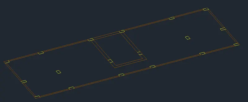
- Add the boundaries for extrusion.
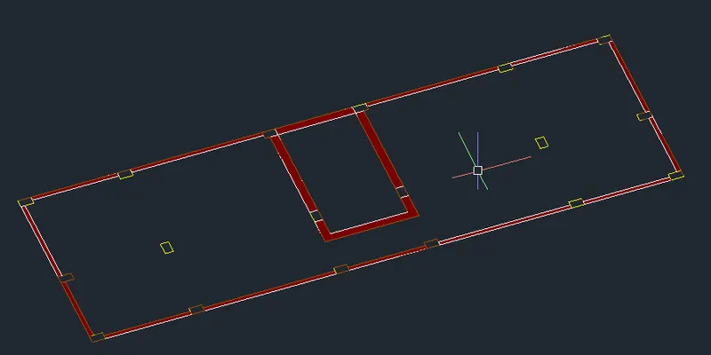
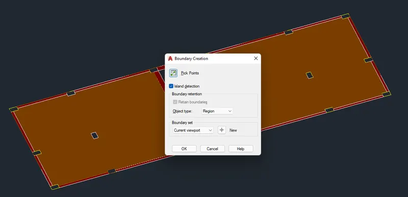
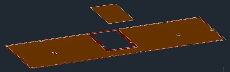
- Extrude to specified height.
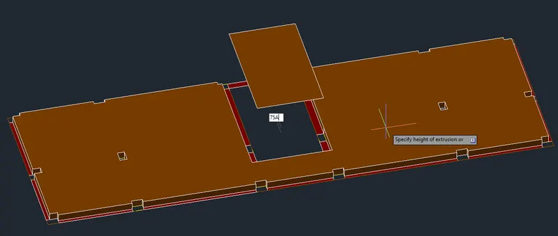
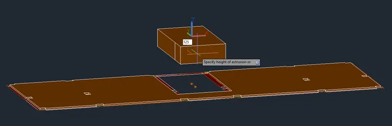
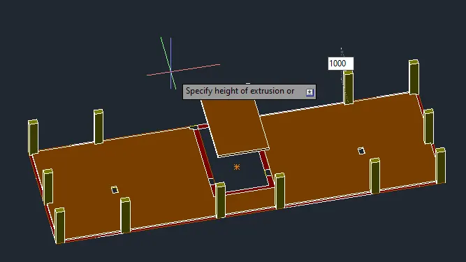
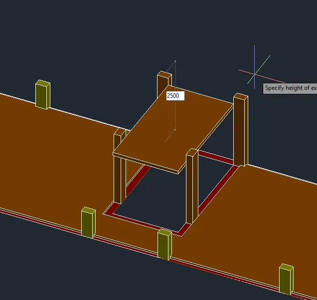
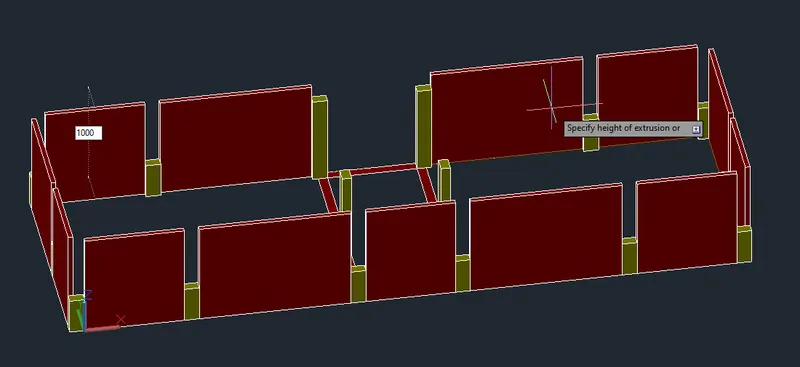
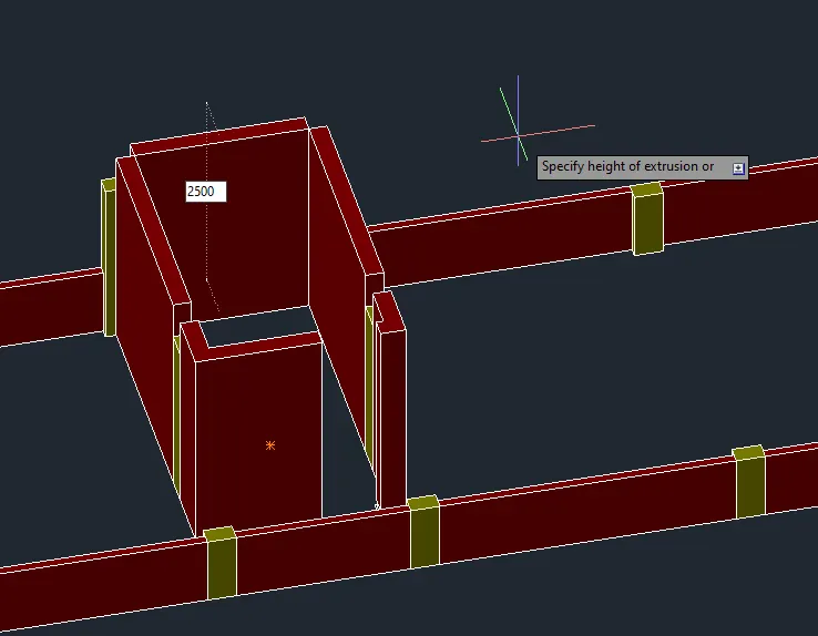
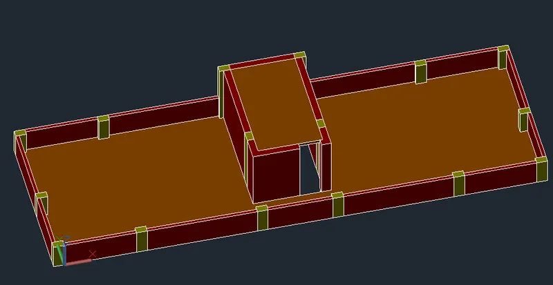
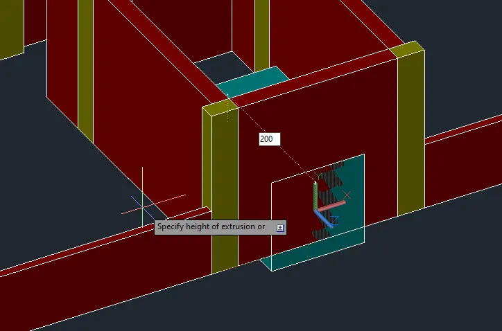
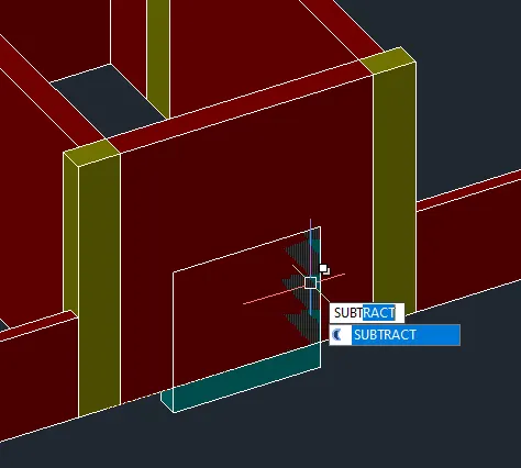
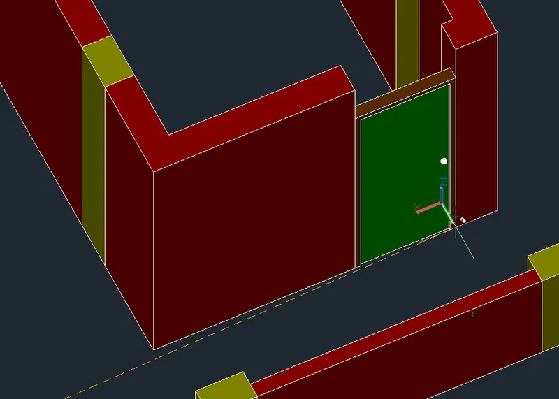
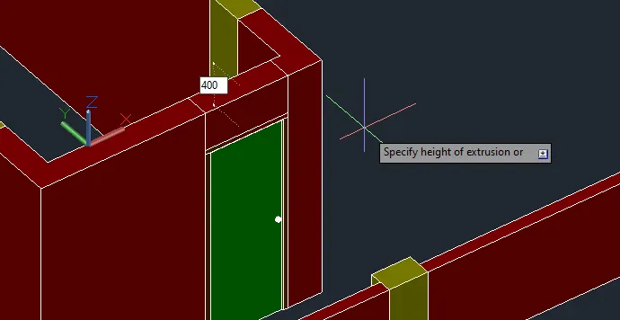
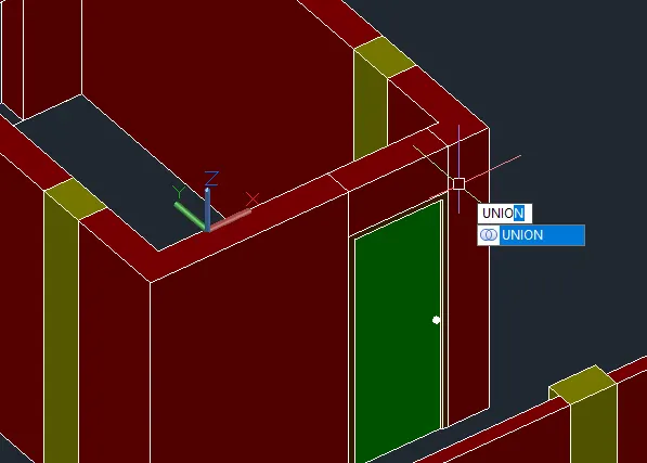
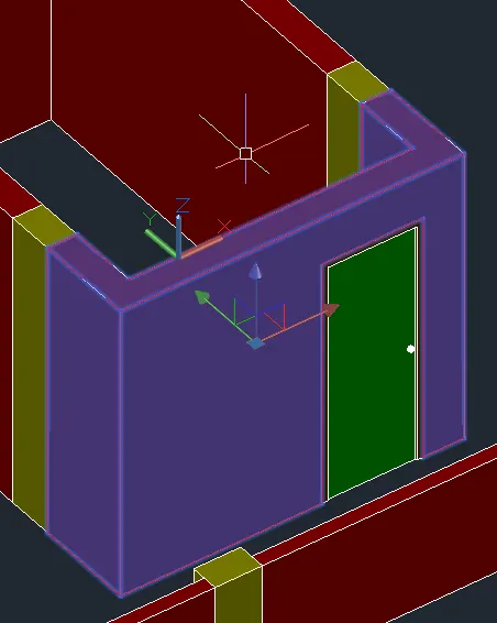
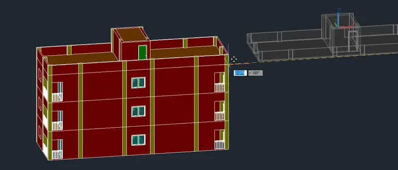
- Create the missing windows then proceed to the first floor.
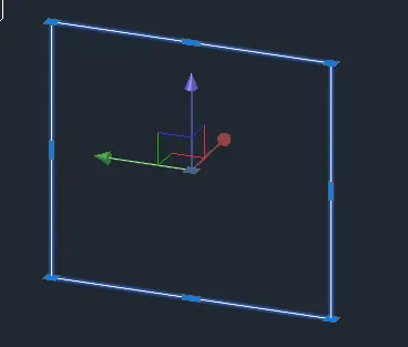
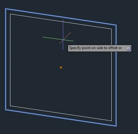
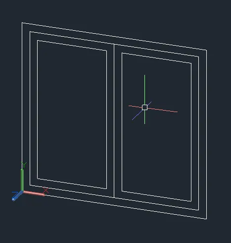
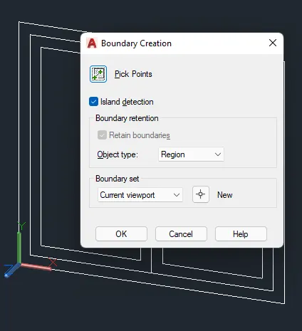
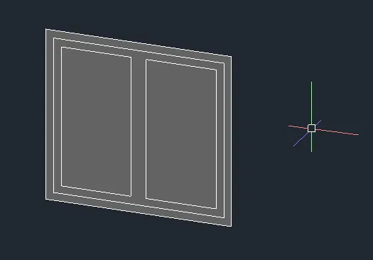
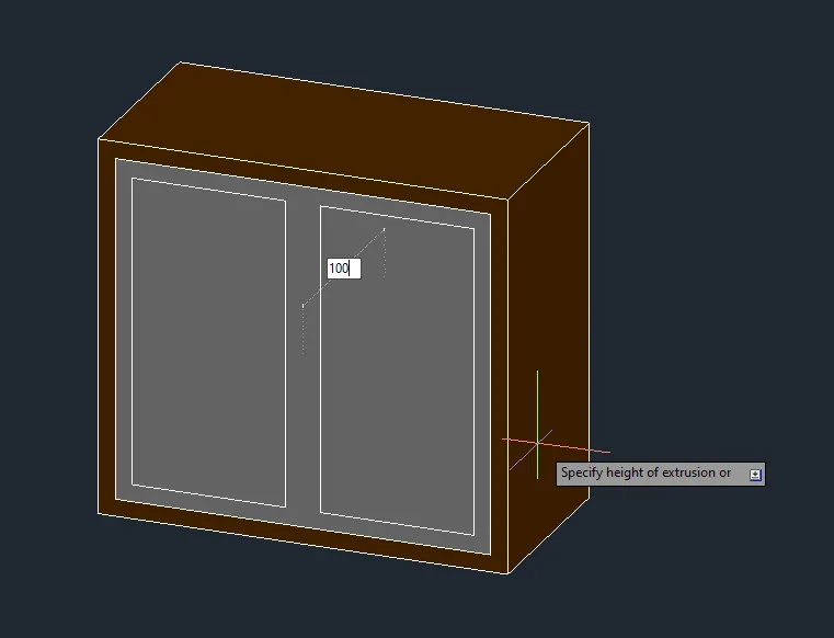
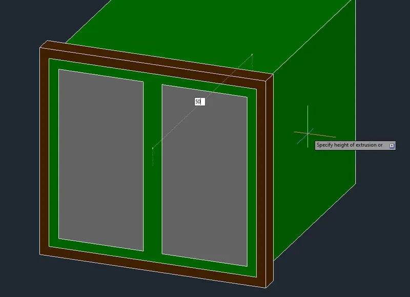
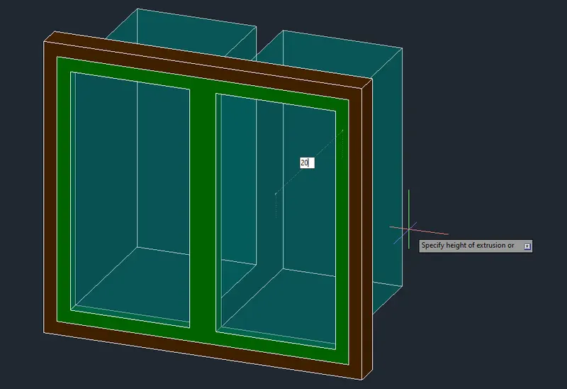
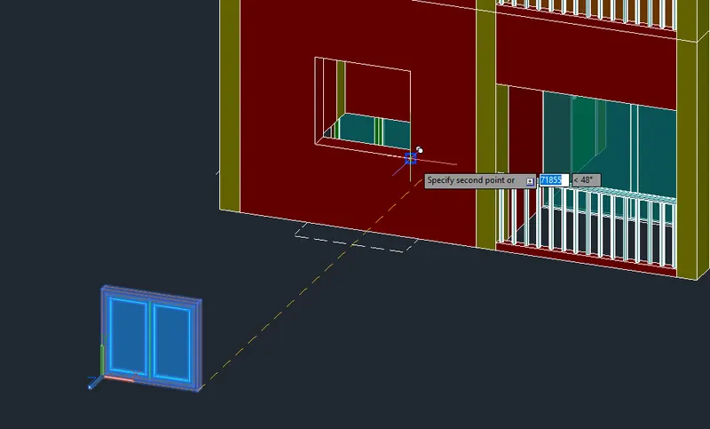
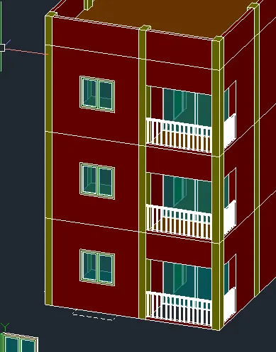
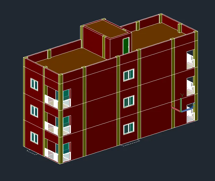
- Proceed with the 1st Floor Plan.
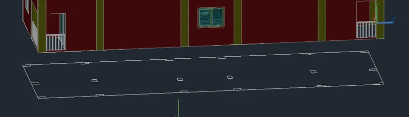
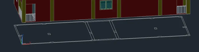
- Add the regions.
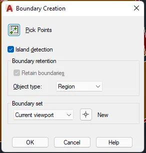
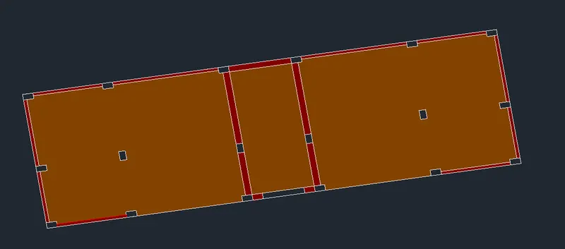
- Extrude and join with the solids.
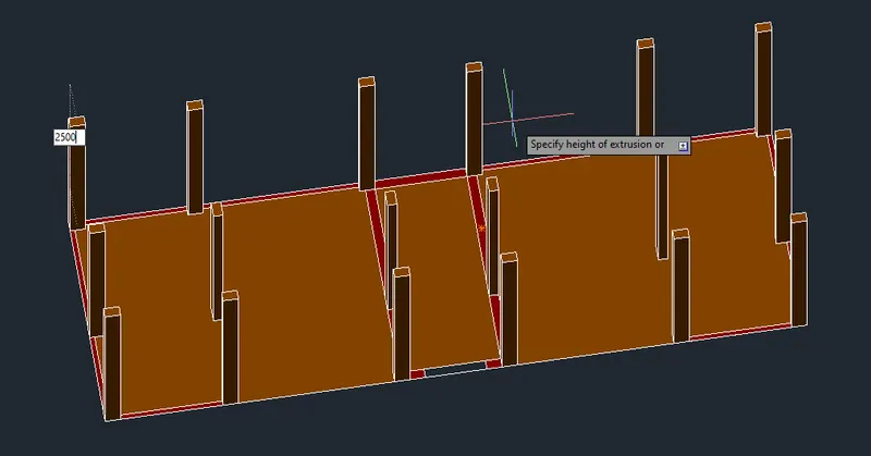
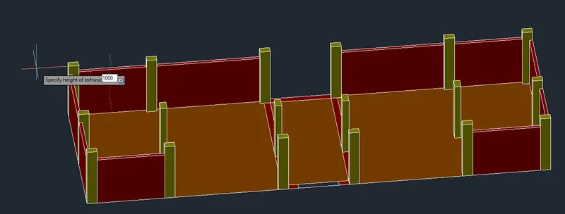
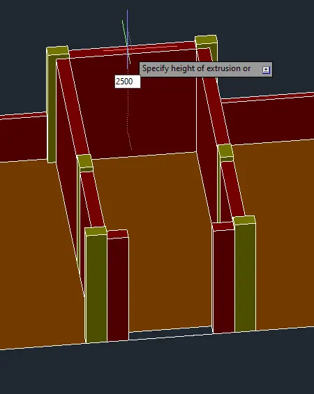
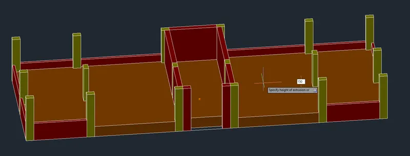
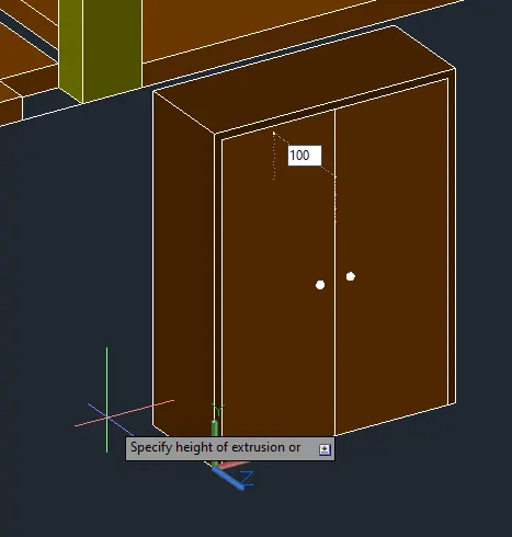
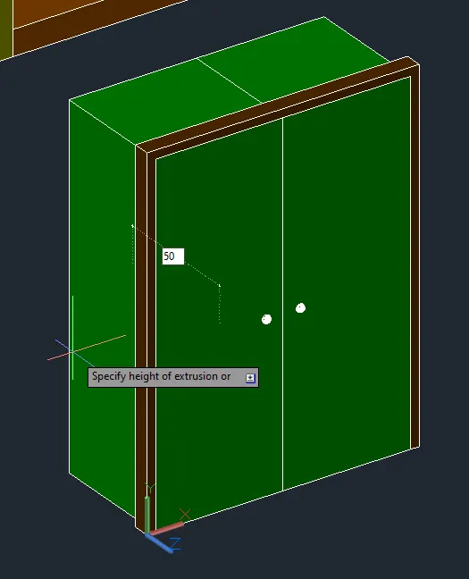
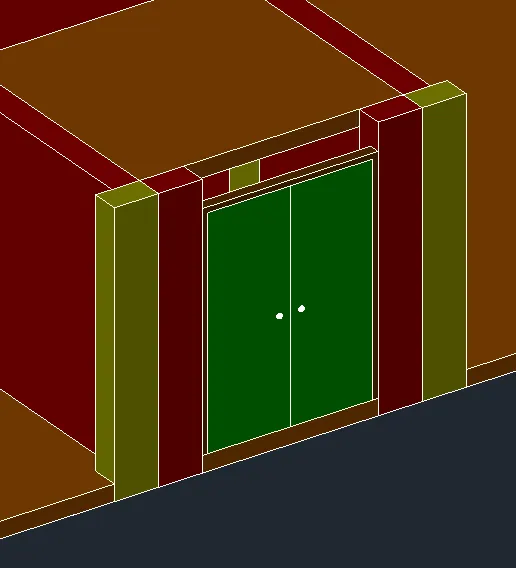
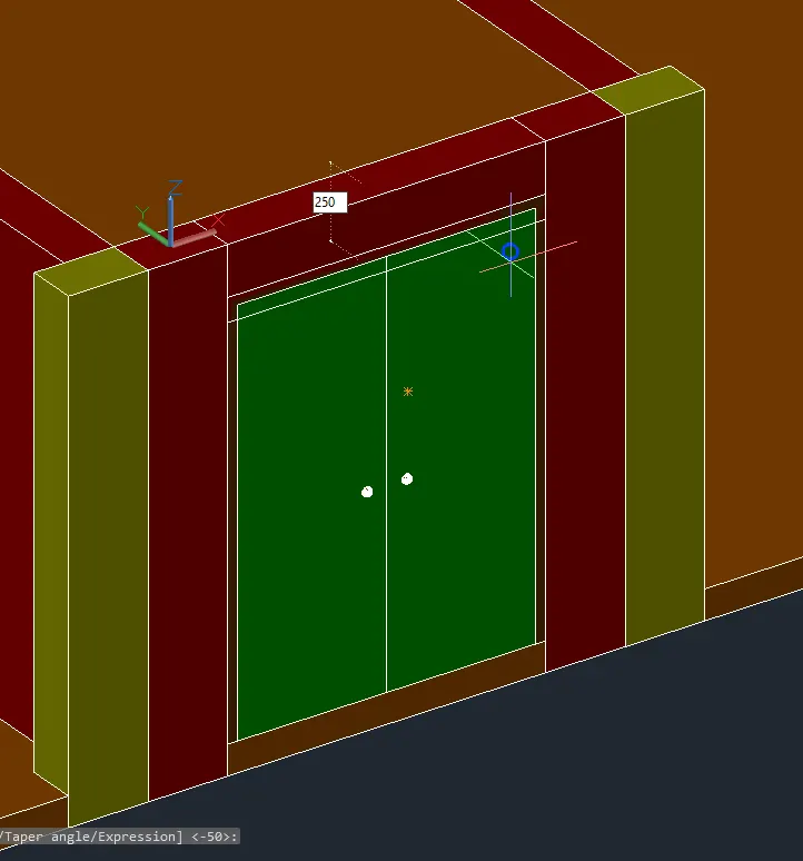
- Add the door.
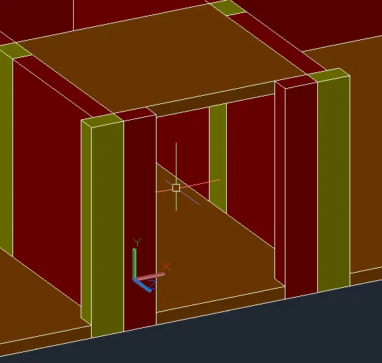
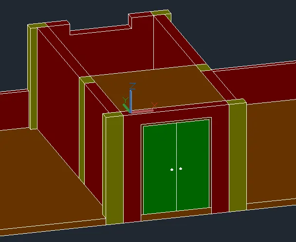
- Add the Slab.
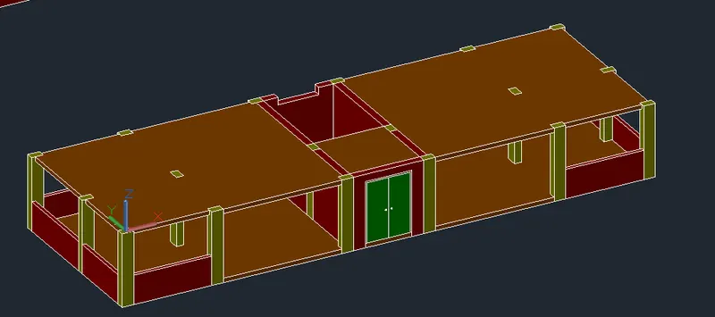
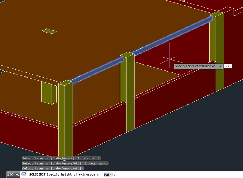
- Use SolidEdit to change the solids.
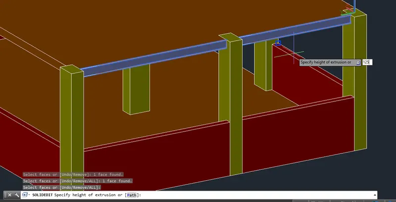
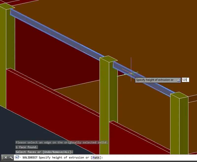
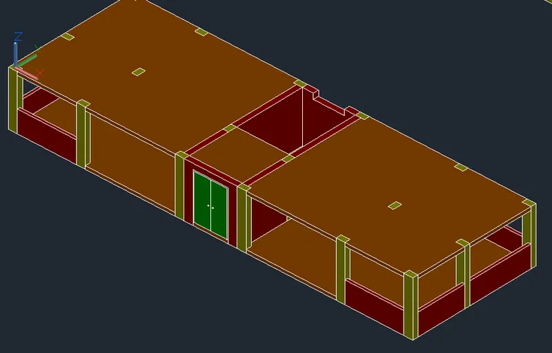
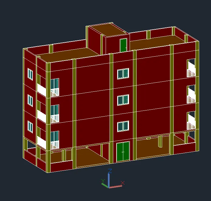
- Union the available solids.
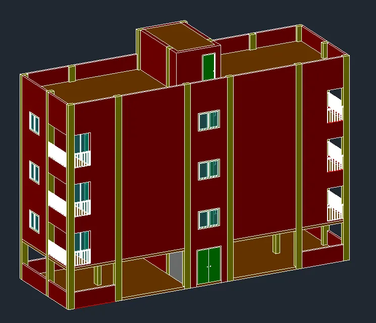
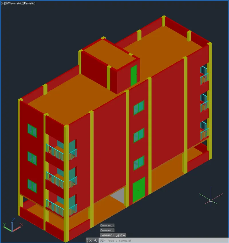
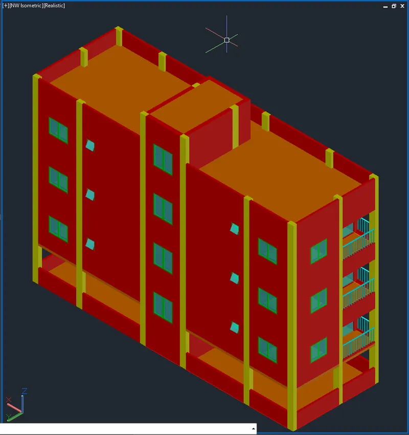
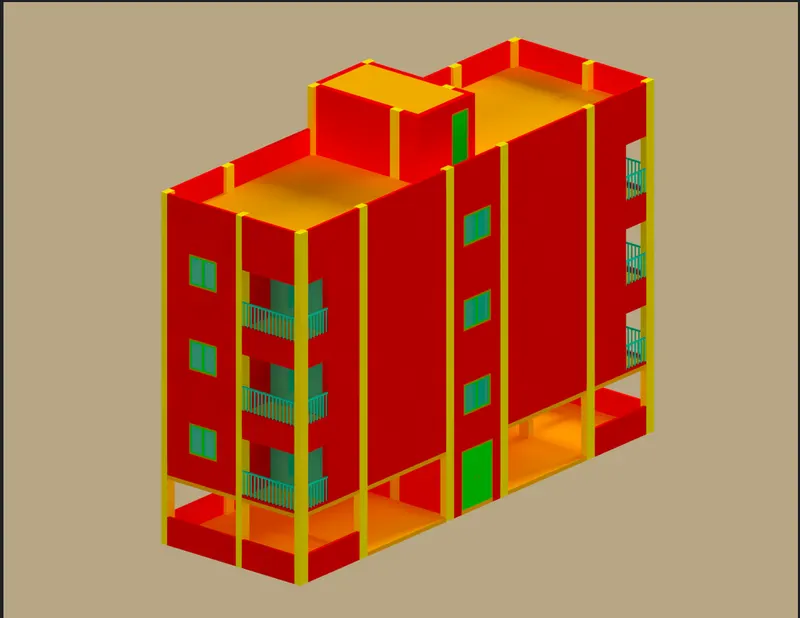
- Add Materials.
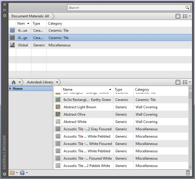
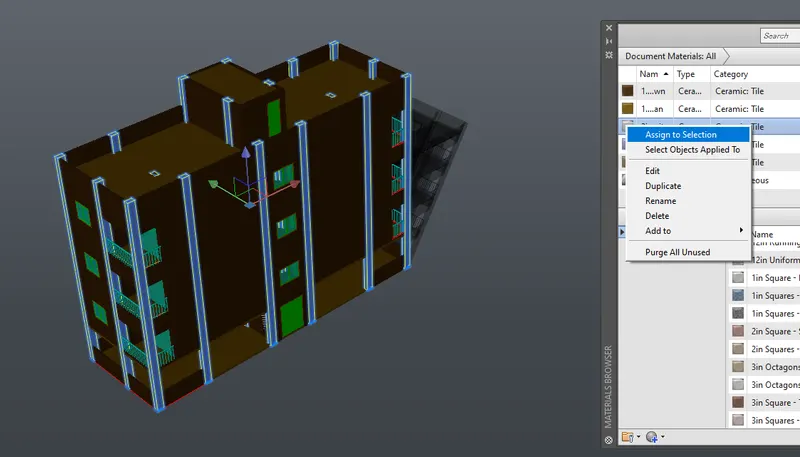
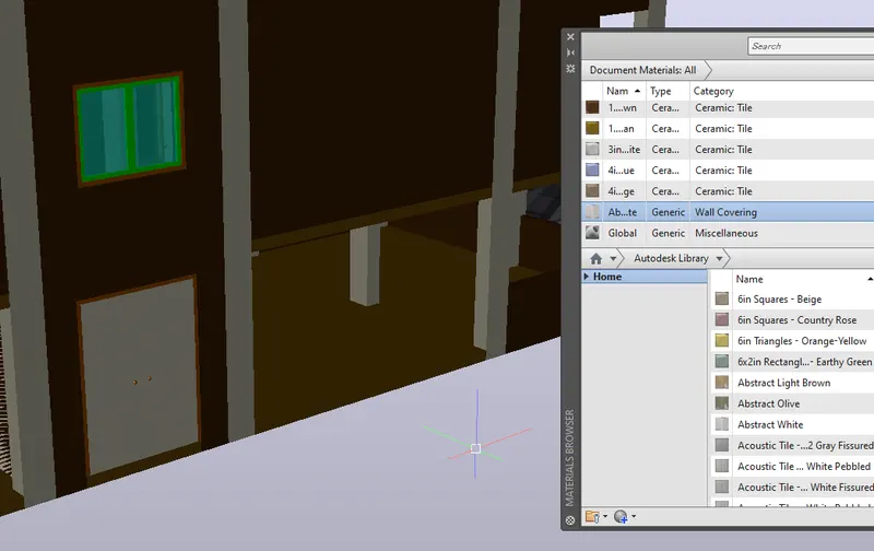
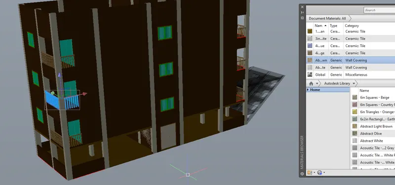
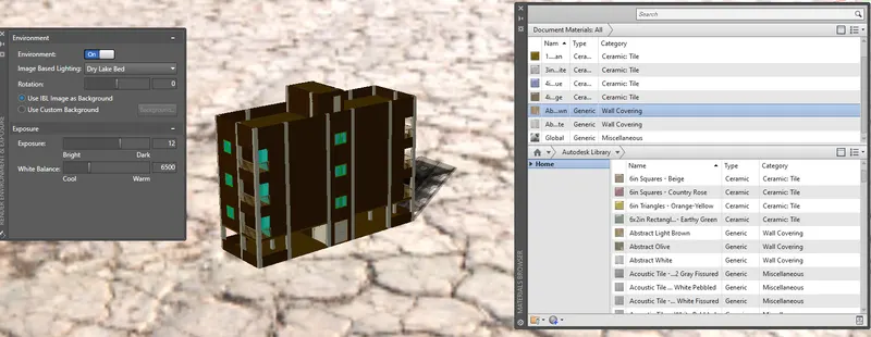
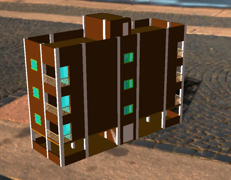
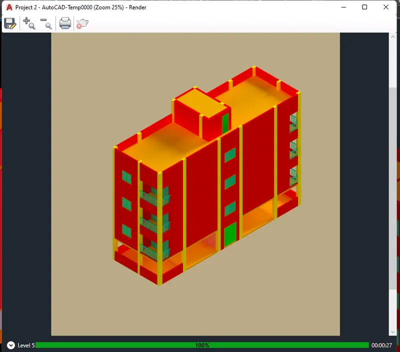
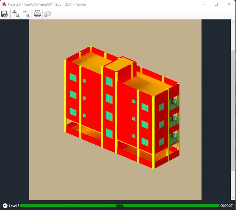
- Now Proceed to Render to Finish.
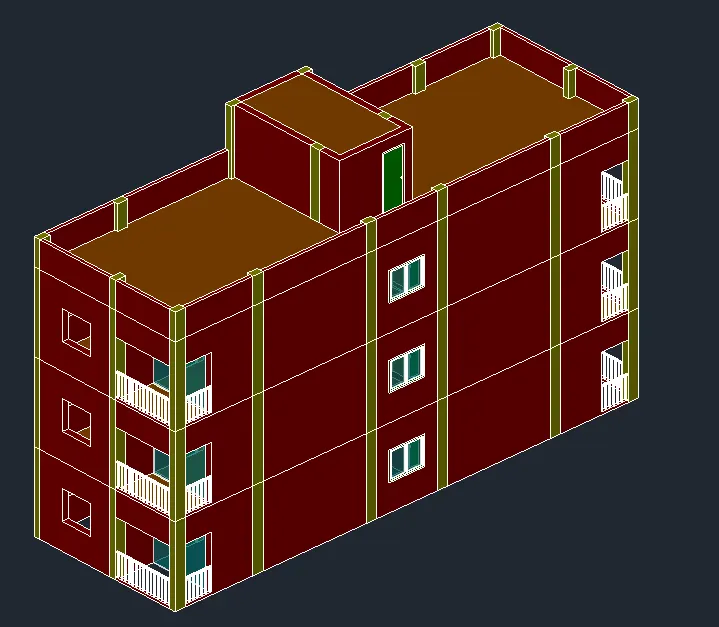
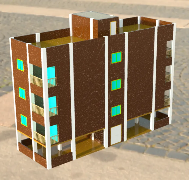
FINAL PRODUCT:
Rendered View.
********************************************************
3. Conclusion
***************
The AutoCAD software allows 3D sketches where solid objects or 3D surfaces are present. By using the 3D function of the AutoCAD software, one can illustrate or convert a 2D sketch into a 3D illustration.
The AutoCAD software also has visualization effects that allows the user to present the created sketches into rendered images. This gives a realistic view of the actual model which is seldom used in the Architectural and Civil Engineering Industry.