Sketch a G+1 residential plan according to Vaastu Shastra and Calculation of Loads as per IS code
Name: Allan Bryan Jayson Cruz
Course: Master’s Certification Program in High-Rise Building Design & Analysis
Date: September 12, 2021
G+1 RESIDENTIAL PLAN WITH VAASTU SHASTRA CONCEPT AND CALCULATION OF LOADS AS PER IS CODE
PROJECT
I. INTRODUCTION
A. Vaastu Shastra
Vaastu Shastra is an ancient Indian science of architecture and acts as a guideline to design your home in the way that enhances positive energy through the locations of each aspect in the building. Our nature is abundant with powerhouses of energy sources like the sun, wind, moon, water earth, and fire. The effects coming from these powerhouses like sunrays, flow of wind, pull of earth's magnetic field and other cosmic energies are used as indication for the Vaastu Shastra concept.
A good home needs to radiate the right kind of energy. A person dwelling in a house comes under the influence of a specific energy field which comes under the influence of a specific energy field. The Vaastu Shastra concept can only be done in a newly constructed home and is not possible for a ready to move in houses.
A.1 Significance of Directions
The eight directions which is classified into two categories namely the Cardinal Directions and the Intercardinal directions signifies an aspect of life and is governed by various gods.
Four Cardinal Directions:
- North - Constitutes to Wealth
- South - Constitutes to Dharma
- East - Constitutes to Overall Prosperity
- West - Constitutes to Overall Prosperity
Four Intercardinal Directions:
- North-east
- North-west
- South-east
- South-west
A.2 Basic Principles of Vaastru Shastra
The Vaastru Shastra concept describes elements found or used inside the residence as symbols that indicate the energy flow. The basic principles followed in Vaastru Shastra are as followed.
- Shape: Rooms should be square or rectangle
- Room Basics: Rooms should be airy, well lit, bright, and clean
- Home Center: The center of the house should be an empty space
- Stairs and Furniture: Heavy furniture should be kept in the south-west direction
- Water: Avoid keeping plants and water features in the bedroom
- Dining Table: Dining space should be near the kitchen and not near the main door
- Mirror Placement: Mirror facing the bed is strictly not allowed. Mirrors in the bedroom need to be placed in such a way that the bed cannot be seen
A.3 Auspicious Directions as per Vaastru Shastra
The Vaastru Shastra concept gives locations on where specific aspects of a building is best located or is to be avoided.
- Kitchen: South-east is the best location. North-east should be avoided.
- Staircase: South-west is the best location. North-east should be avoided.
- Toilet: North-west is the best location. North-east should be avoided.
- Master Bedroom: South-west is the best location.
- Guest Room: North-west is the best location.
- Living Room: North-west is the best location.
- Over Head Tanks: West is the best location.
- Under Ground Tanks: North-east is the best location. South-west should be avoided.
A.4 Guidelines For House Elements
The Vaastru Shastra concept gives further specifications to important parts of the house that gather the most energy or is an important aspect in what kind of energy is formed in the house.
I. Gateway (Entrance) of the House:
- The main entrance is not only the entry point for the family but also the energy that circulates the home.
- The main door should be stronger and bigger than other doors in the house and should be made of superior quality wood, preferably teak wood.
- The main door should not be dark as good energy is associated with bright and happy places.
- Garbage bags, unwanted things, and shoes should be kept away from the main door.
- The main door should open inward and avoid creaky sounds.
- The main door should be constructed in a way to ensure that when you step out, you face the North, East, or North-east direction.
- Avoid painting the main door black and placing animal statues near the door.
- South-west location should be avoided in placement of the main door.
II. Living Room:
- Living room should be cluster free. It is a place where the family spends most time together.
- Living room should face East, North, or North-east. North-west facing living room is also favorable.
- Heavy furniture should be kept in the West or South-west direction of the living room.
- Electronic appliances should be installed in the South-east section of the living room.
- If planning for a mirror in this room, ensure you place it in the North wall.
- An aquarium on the North or East wall should be placed for prosperity.
- A bright picture of sunrise in the southern wall is good.
- Shades of color Yellow, Green, Beige, or Blue can be placed on walls to infuse liveliness and vibrancy.
III. Bedroom:
- Bedroom in South-west direction brings good health and prosperity.
- Avoid bedroom in North-east as it may cause health issues.
- Avoid on putting the bedroom at the South-east zone as it may cause quarrel among couples.
- Bed should be placed in the South-west corner of the bedroom with head facing west.
- Avoid placing a mirror or television in front of the bed because the reflection causes fight and other domestic disruptions.
- Avoid having paintings depicting water or a fountain as it could cause emotional outbursts.
- Using of aromatic oils can create an oasis of calm.
- Never sleep with your head in the North.
- Avoid overhanging beams in the room to enjoy good health.
- Use solid wooden beds instead of hollow wrought-iron beds.
- Paint the bedroom walls in neutral or earthy shades that radiates positive energy.
- Bedrooms are the place for rest and repose. It is good to have soothing wall colours for a peaceful aura.
IV. Pooja Room:
- Rooms in a house for meditation and prayers will ensure spiritual growth.
- East or North-east part of your home is perfect for meditation, Yoga, and spiritual pursuits.
- Facing East when you meditate will increase positivity.
- White, Beige, or a light Yellow or Green are great colour options for a meditation room.
- Create a sacred altar and decorate with candles or incense sticks.
V. Kitchen:
- Following Vaastu Shastra for kitchen ensures a healthy life for your family growth.
- Keep water sink away from the gas stove.
- Fridge needs to be placed at South-west corner.
- Never let your kitchen face a washroom wall nor share a common wall with it.
VI. Study Room:
- Select a square or rectangle shape for the study table.
- Don't place the table facing a blank wall or window.
- Placing a table in the North-east, East, or West direction is ideal.
- Hanging bookshelves are best avoided.
VII. Courtyard:
- Brahmasthan is a unique feature of ancient Architecture based on Vaastu Shastra.
- It is the center of your residence and the holiest and most powerful zone.
- A traditional home in Kerala, the courtyard is always at the center of the house.
- This part should be perfect and clutter-free.
- The placement of the kitchen, bathroom, or pillar/beam near the courtyard attracts negative energy so it should be avoided.
The Vaastu Shastra will create harmony inside a home so following its teachings is highly recommended. It will create a difference especially in the atmosphere of the house when followed.
B. Structural Loads
Structural loads are forces applied to the structure components which is an important consideration in the design. The assessment of their effects is carried out by the structural analysis. The Building codes require the structure to withstand all forces during their service life that is why the calculation of loads is important in the design of structures. The estimation of the total load acting on a structure considering the future is calculated accurately and the same should be designed.
B.1 Requirements for Designing of a Building
- Selection of good structural system to resist Gravity, Wind, and Seismic forces
- Proper Analysis and design
- Good detailing
- Quality Construction Monitoring
B.2 Resistance Required tp Protect a Building
- Shear Failure
- Flexural Failure
- Axial Failure
B.3 Indian Codes & Standards
- IS 456:2000 - Revised in 2016 for Reinforced Concrete Structures
- IS 875:1987 - Revised in 2018 (Part-I) for Dead Load
- IS 875:1987 - Revised in 2008 (Part-II) for Live Load
- IS 875:1987 - Revised in 2015 (Part-III) for Wind Load
- IS 1893:2016 (Part-I) for Seismic Load
- IS 13920:1993 for Seismic Detailing
B.4 Classification of Structural Loads
1. Vertical Loads
1.1 Dead Loads
Dead loads are permanent loads acting on a structure throughout their life span. These loads are stationary loads that occur mainly due to the self-weight of the structure. Dead loads are called from the structural members, fixed partitions, fixed equipment etc. Weight of structural elements are considered as deads of the structure.
Calculation Procedure:
Dead loads are calculated by multiplying the quantity of each material with the unit weight of the specific material. The unit weight of the different materials are listed in the below:
- PCC (Plain Cement Concrete) - 24kN/m3
- RCC (Reinforced Cement Concrete) - 25kN/m3
- Structural Steel - 78.5kN/m3
- Brick Masonry - 20kN/m3
- Stone Masonry - 24kN/m3
- Floor Finish - 0.6~1.2 kN/m3
Step 1. Determine the unit weight of each elements considered as dead load. This can be taken from Table 1 of IS 875 (Part 1) Unit Weight of Building Materials.
Step 2. Calculate the volume of each elements. The volume is calculated by multiplying the length, width, and thickness of the structural element.
Step 3. Multiply the colume of the structural element to its specified unit weight. The dead load of the structure is taken as kN.
1.2 Live Loads
Live loads are real-time loads. These are also called Imposed Loads or Sudden Loads. Live loads in a structure changes with respect to time. Live load includes the weight of the furniture, people occupancy, etc. The design of the structure must conform to IS 875 (Part-2). The code has clearly mentioned the minimum load to be considered for all type of building according to their occupancy.
Different Types of Occupancies
- Residential Buildings
- Educational Buildings
- Institutional Buidlings
- Assembly Buildings
- Business & Office Buildings
- Mercantile Buildings
- Industrial Buildings
- Storage Buildings
Calculation Procedure:
Step 1. Determine the type of occupancy of the structure.
Step 2. Determine the live load of the structure using Table 1 of IS 875 (Part 2) Imposed Floor Loads for Different Occupancies.
1.3 Snow Loads
This load is considered in structures that receives snowfall. This loads are calculated by the projections made by snow at different parts of the structure. The amount of snow depends on the height of the building, size and shape of roof. Normally, it is designed as per IS Code 875 (Part 4):1987. The minimum snow load on any area above ground or roof accumulated is obtained by the formula:
S = uSo
Where:
S = Design snow load
u = Shape Coefficient
So = Ground Snow Load
In this residentail house building, snow load will not be provided.
2. Horizontal Loads
2.1 Wind Loads
When the height of a building is more than 10m, the building needs to be designed for Wind Load. These horizontal loads are caused by wind acting on the structure. Wind load acts horizontally towards walls and roof surface.
Calculation Procedure:
Step 1. Calculate the Design Wind Speed (Vz)
Vz = Design wind speed at height z, in m/s
= Vb x k1 x k2 x k3 x k4
Where Vb, k1, k2, k3, and k4 are as described below.
a) Basic Wind Speed (Vb)
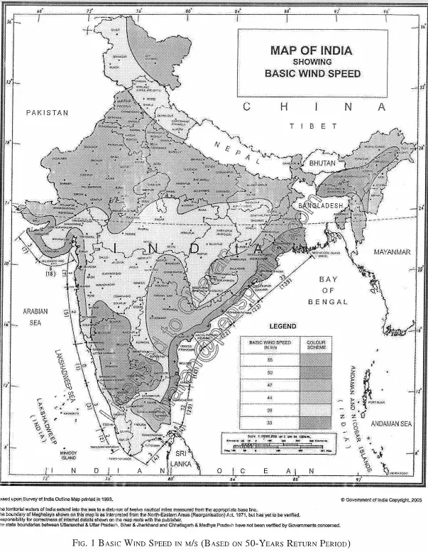
The basic wind speed can be taken from Figure 1 of IS 875 Part III entitled Basic Wind Speed in m/s (Based on 50-years Return Period). The wind speed varies between 55, 50, 47, 44, 39, and 33 m/s depending on its location within the given map.
b) Probability Factor / Risk Coefficient (k1)
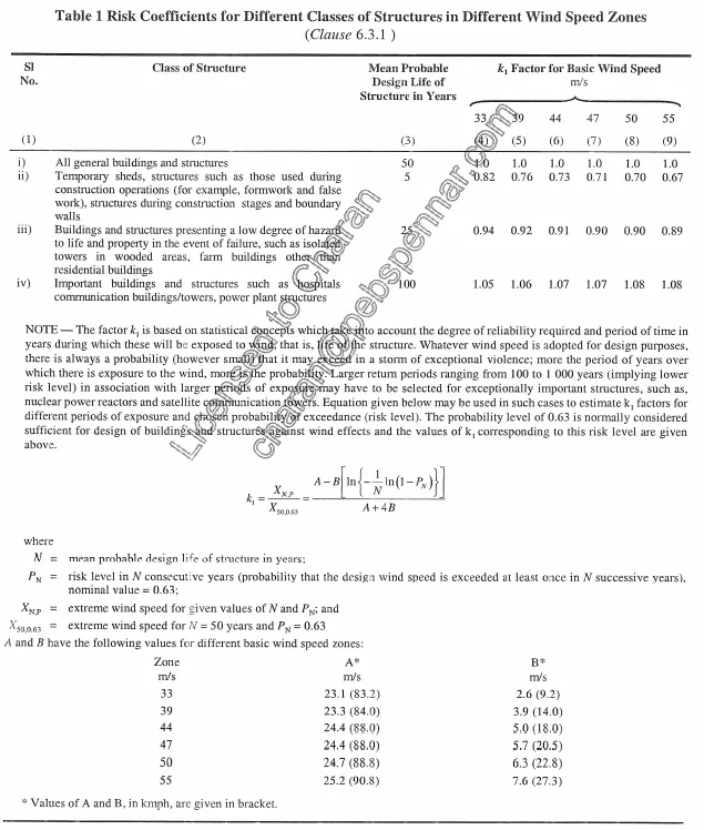
This value can be taken from Table 1 Risk Coefficient For Different Classes of Structures in Different Wind Speed Zones. In the design of buildings and structures, a regional basic wind speed having a mean return period of 50 years shall be used except as specified in the note of Table 1. In the table, the values for k1 is determined by the class of the structure and its life span in years.
c) Terrain Height Factor (k2)
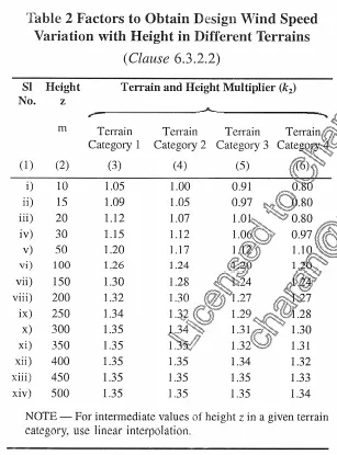
This value can be taken from Table 2 Factors to Obtain Design Wind Speed Variation with Height in Different Terrains. This factor is divided into 4 categories:
- Category 1 - Exposed open terrain with few or no obstructions and in which the average height of any object surrounding the structure is less than 1.5m. Typically, this category represents open sea-coasts and flat plains without trees.
- Category 2 - Open terrain with well scattered obstructions having heights generally between 1.5m and 10m. This is the criterion for measurement of regional basic wind speeds and represents airfields, open park lands and underdeveloped sparsely built-up outskirts of towns and suburbs. Open land adjacent to sea coast may also be classified in this category due to roughness of large sea waves at high winds.
- Category 3 - Terrain with numerous closely spaced obstructions having the size of buildings/structures up to 10m in height with or without a few isolated tall structures. This category represents well wooded areas, and shrubs, towns and industrial areas full or partially developed.
- Category 4 - Terrain with numerous large high and closely spaced obstructions. This category represents large city centers, generally with obstructions above 25m and well developed industrial complexes.
Once the category is known, determine the k2 factor depending on the height of the structure.
d) Topography Factor (k3)
The effect of topography shall be significant at a site when the upwind slope is more than 3degrees, and below that, k3 value may be taken as 1.0. k3 value ranges from 1.0~1.36 for upwind slope greater than 3degrees. It varies with height above ground level, at a maximum near the ground, and reducing to 1.0 at higher levels. For evaluating the value of k3 greater than 1.0, refer to Appendix C of IS 875 Part 3.
e) Importance Factor for the Cyclonic Region (k4)
As stated in Clause 6.3.4 of IS 875 Part 3, studies of wind speed and damage to buildings and structures point to the fact that the speeds given in the basic wind speed map are often exceeded during the cyclones. The effect of cyclonic storms is largely felt in a belt of approximately 60km width at the coast. In order to ensure better safety of structures in regions prone to cyclones, the following values of k4 (as recommended in IS 15498) are stipulated as applicable according to the importance of the structure:
- Structures of post-cyclonic importance for emergency services (such as cyclone shelters, hospitals, schools, communication towers, etc) ; k4 = 1.30
- Industrial Structures ; k4 = 1.15
- All other Structures ; k4 = 1.00
Step 2. Calculate Wind Pressure (Pz)
Pz = Wind pressure at height z, in N/m^2
= 0.6 Vz^2
Where Vz is the design wind speed described in Step 2.
Step 3. Calculate Design Wind Pressure (Pd)
Pd = Design wind pressure, in N/m^2
= Kd x Ka x Kc x Pz
Pd shall not be taken as less than 0.7 Pz.
Where Pd is taken from step 2 while Kd, Ka and Kc are described below.
a) Wind Directionality Factor (Kd)
Kd is described in Clause 7.2.1. It may be taken as the following values:
- Kd = 0.9 - Specified that for buildings, solid signs, open signs, lattice frameworks, and trussed towers (triangular, square, rectangular)
- Kd = 1.0 - For circular or near-circular forms.
- Kd = 1.0 - For cyclone affected regions.
- Kd = 1.0 - When considering local pressure coefficients
b) Area Averaging Factor (Ka)
Ka factor is described in Clause 7.2.2. As the area becomes larger, the correlation of measured values decrease and vise -versa. The decrease in pressures due to larger areas may be taken into account as given in Table 4 Area Averaging Factor (Ka).
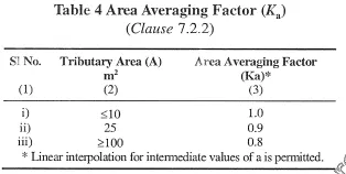
The tributary are is divided into two as described in Clause 7.2.2.1.
- Overall Structure - For evaluating loads on frames, the tributary area shall be taken as the centre to centre distances between frames multiplied by the individual panel dimension in the other direction together with overall pressure coefficients.
- Individual Elements - For beam type elements, purlins, etc, the tributary area shall be taken as effective span multiplied by spacing. The effective span is the actual span for mid span and cantilever load effects; and half the sum of adjacent spans for support moments and reactions.
c) Combination Factor (Kc)
This factor is described in Clause 7.3.3.13. When taking wind loads on frames of clad buildings, it is reasonable to assume that the pressures or suctions inside and outside the structure shall not be fully correlated. Therefore when taking the combined effect of wind loads on the frame, a reduction factor of Kc = 0.9 may be used over the building envelope when roof is subjected to pressure and internal pressure is suction, or vice-versa.
Step 4. Calculate the Wind Load on Individual Members (F)
The formula for the wind load on individual members is taken from Clause 7.3.1.
F = (Cpe - CPi) A Pd
Where the parameters needed for calculating the wind load is described below. These parameters are Roof Angle, Cpe, Cpi, and A. Pd or the design wind pressure is described in step 3.
a) External Pressure Coefficient (Cpe)
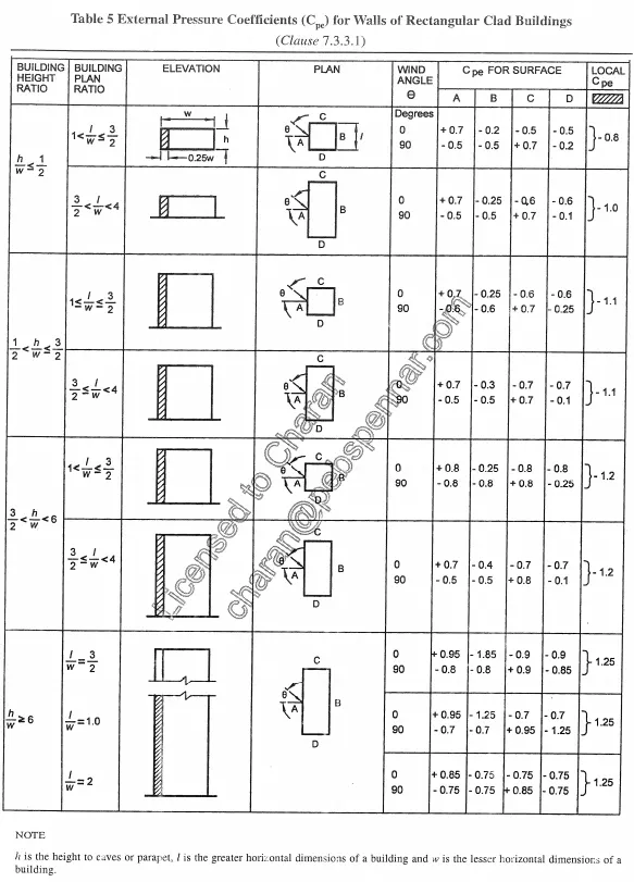
The external pressure coefficient for a Monoslope steel building can be taken from Table 5 (For walls) and Table 7 (For the monoslope roof). The monoslope angle is used to determine the Cpe coefficient together with the wind angle.
Note 1: If the surface design pressure varies with height, the surface areas of the structural element may be sub-divided so that the specified pressures are taken over appropriate areas.
Note 2: Positive wind load indicates the force acting towards the structural element and negative away from it.
For External Pressure Coefficient of Walls
Table 5 of IS 875 Part 3 is used. The height to width ratio is used to determine what case to be used. Furthermore, the building plan ratio (l/w) is also taken into account.
b) Internal Pressure Coefficient (Cpi)
The internal pressure coefficient is described in Clause 7.3.2. The internal pressure coefficient can be taken as one of the values below:
- +0.2 / -0.2 ; Where the claddings permit the flow of air with open buildings not more than 5 percent of the wall area but there is no large openings.
- +0.5 / -0.5 ; Buildings with medium openings about 5 to 20 percent of wall area.
- + 0.7 / -0.7 ; Buildings with large openings larger than 20 percent of the wall area.
The design conditions shall be examined with two values. It is algebraically added to the external pressure coefficients and the analysis which indicates greater distress of member shall be adopted. In most situations a simple inspection of the sign of external pressure will at once indicate the proper sign of the internal pressure coefficient to be taken for design.
c) Surface Area of Structural Element or Cladding Unit (A)
This will be calculated base on the dimension given. It is a simple length x width where length and width is taken from the calculated dimensions.
2.2 Seismic Loads
The seismic load calculation procedure is divided into three methods.
I. Response Spectrum Method (RSM)
Response spectrum method is the dynamic response of a structure against earthquake ground motion by natural period and the damping coefficient of the structure.
It is calculated from the empirical formula for the calculation of frequencies for various type of structures like:
- RC Framed Buildings, Ta = 0.075 * h^(0.75)
- Steel Framed Buildings, Ta = 0.085 * h^(0.75)
- All other Buildings with Brick Infills, Ta = 0.09 * h/`root`d
II. Seismic Coefficient Method (SCM)
The seismic coefficient method is used assuming the structure is rigid and the fixidity of the structure to the ground is perfect. In this method, all points in the structure experience same accelerations during ground motion. The effects of earthquake are considered as equivalent lateral forces.
Procedure
Step 1. Identify the Earthquake zone for which the structure needs to be designed.
This is based on project site location and can be specified by the Owner of the project or the Engineer in charge.
Step 2. Zones can be identified from the map provided in the IS code.
The Zones are denoted from Zone II to Zone V. It can be determined in IS 1893 (Part 1):2002. Zone II being the least active region while Zone V is the most active region. The zoning image is given below.

Step 3. Calculate the design horizontal seismic coefficient Ah.
The Horizontal Seismic Coefficient Ah is calculated using the formula below.
`Ah = (Z * I * Sa)/(2R * g)`
Provided for any structure with T<0.1s, the value of Ah will not be taken less than Z/2 whatever the value of I/R
Where;
Z = Zone Factor
I = Importance Factor
R = Response Reduction Factor
Sa/g = Average response acceleration coefficient
T = Undamped Natural period of vibration of the structure
The parameters needed for the calculation of Horizontal Seismic Coefficient is described below.
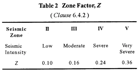
a) Zone Factor (Z)
Zone Factor Z is the value of peak ground acceleration given in the units of "G" for the maximum considered earthquake. The Value Z/2 corresponds to the design basis earthquake-damage control limit state. The Zone Factor is taken from Table 2 of IS 1893 (Part 1):2002. It is divided into 4 Zones which is described in step 2.
b) Importance Factor (I)
I is the importance factor. The permitted damage to a structure can be reduced by setting this value to more than 1.0. The value of I is taken from Table 6 of IS 1893 (Part 1):2002. The importance factor is identified by the type of the structure.
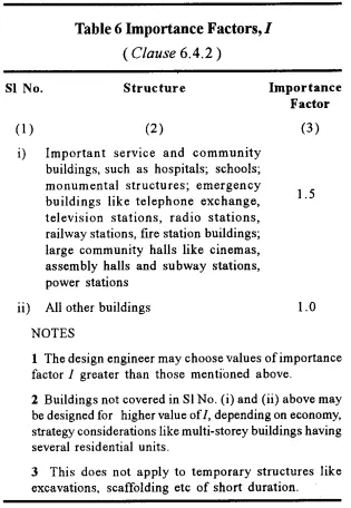
The ratio of R/I defines the permitted damage to a structure.
c) Response Reduction Factor (R)
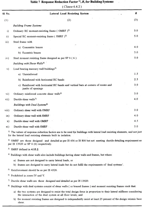
R is the response factor and it controls the permitted damage in the design basis of earthquake. The minimum value of R is 3 while the maximum value for R is 5. The higher value indicated for a structure is always used. The response factor is taken from Table 7 of IS 1893 (Part 1):2002. It is determined base on the type of building frame system followed by the structure.
d) Average response acceleration coefficient (Sa/g)
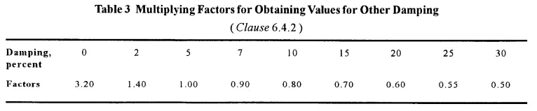
The Sa/g coefficient is determined base on the classification of soil where the structure is built. Sa is the spectral acceleration to be established in m/s and Sa/g as dimension value. For 5% damping percentage, three different curves are recommended in IS 1893. The classification of soil is based on shear wave velocity for top 30m of rock/soil layer based on SPT (Standard Penetration Test) values. These are as follows:
- Class I : Rock or Hard Soil (N > 30)
- Class II : Medium Soil (N between 10 & 30)
- Class III : Soft Soil (N < 100)
The value of Sa/g is described in Clause 6.4.5 of IS 1893 (Part 1):2002.
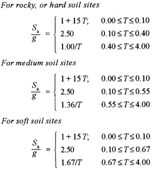
The proposed 5 percent spectra for rocky and soil sites are shown in Figure 2 of IS 1893 (Part 1):2002.
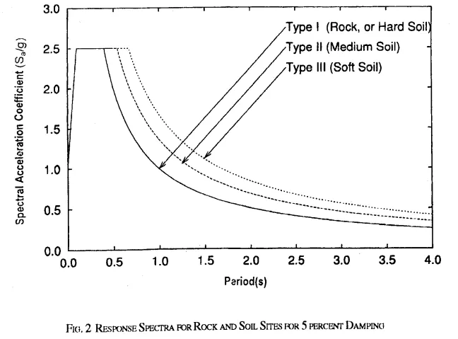
For other damping percentage, the IS Code 1893 (Part 1):2002 has given multiplying factors in Table 3.
e) Undamped Natural Period of Vibration of the Structure (T)
This is the time period of undamped vibration. This can be calculated using Clause 7.6 Fundamental Natural Period (Ta) or specified within the project. Ta is described in Part I Response Spectrum Method (RSM).
Step 5. Calculate the design seismic base shear for the Structure (VB).
The design base shear is the sum of the lateral forces applied at all levels that are finally transferred to the ground. It is calculated using the formula below.
VB = W x Ah
Where;
W = Seismic weight of the building (Total volume x Unit weight of material), in kN
Ah = Horizontal seismic coefficient, which is described in step 3.
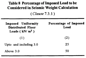
For the application of imposed dead load in the Seismic weight of the building, IS 1893 (Part 1):2002 provided Table 8 Percentage of Imposed Load to be Considered in Seismic Weight Calculation.
Step 5) Calculate the design forces on the structure.
The design forces of the structure is calculated using the formula given below.
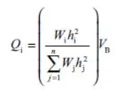
Where;
Qi = Design lateral force at floor 1
VB = Design seismic base shear
Wi = Seismic weight of the floor i
hi = Height of the floor i from the base
n = Number of storeys of the building at which masses are located.
III. Time-History Analysis (THA)
It is an analysis of the dynamic response of the structure at each increment of time, when its base is subjected to a specific ground motion time history. The steps in part two is followed with time variations.
C. Aim of this Project
The aim of this project is to provide a G+1 sketch of a residential house including the load calculations that will be applied in the design. This project will also provide the drawing requirements needed on site to proceed with the construction without any missing information. The residential house sketched in this project will portray the specifications given by Vaastru Shastra Concept in terms of the location of bedrooms, toilet, main-entrance, and other house elements provided in the sketch. Step-by-step procedures for the calculation of loads is provided to further discuss the appropriate methods in calculating loads needed for the design.
*************************************************
II. DRAWING SKETCH AND SITE REQUIREMENTS
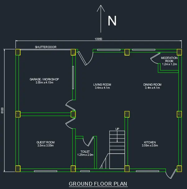
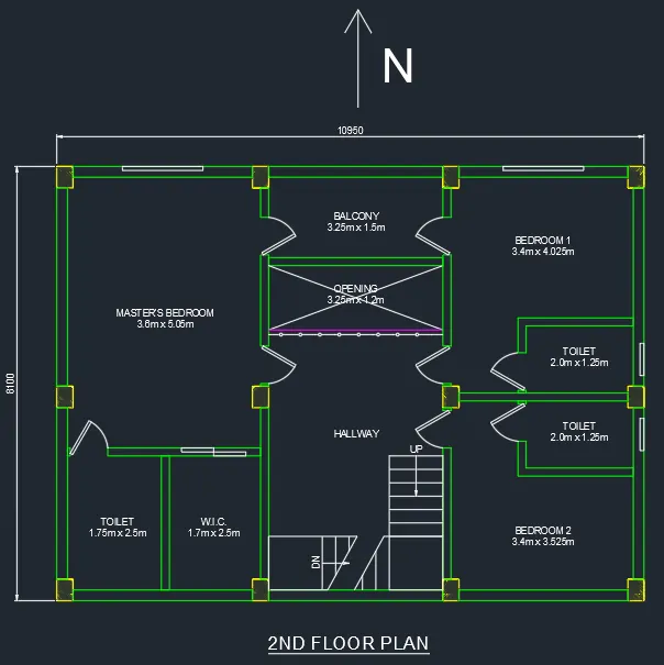
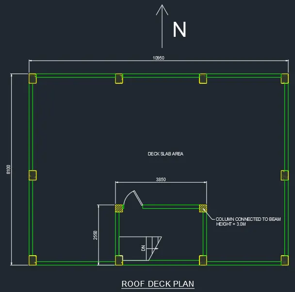
D. Sketch of G+1 Residential House
In the sketch of the G+1 Residentail House, the layout of each aspect of the house and its dimensions are provided. The doors locations are provided as well as the location of the windows.
D.1 Ground Floor Plan
D.2 First Floor Plan
D.3 Roof Deck Plan
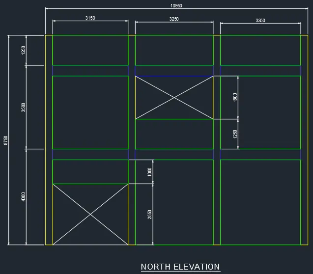
D.4 North Elevation
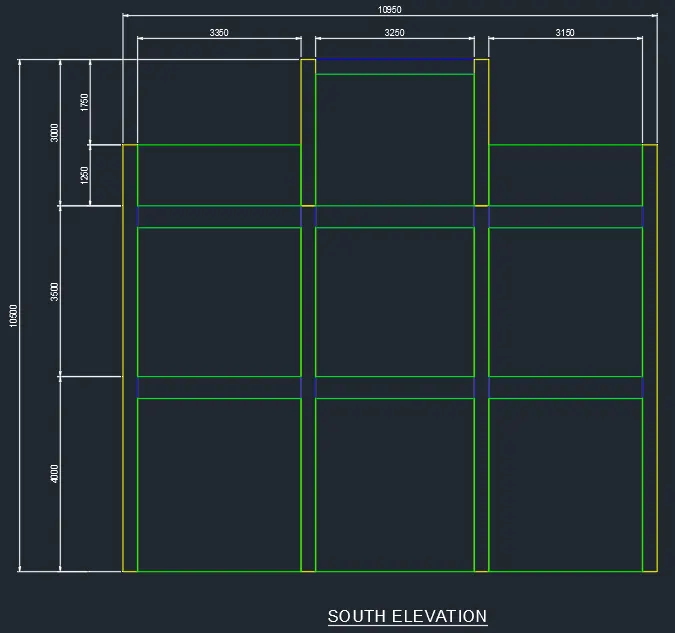
D.5 South Elevation
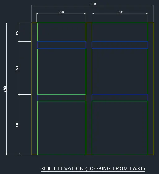
D.6 East and West Side Elevation
E. Site Drawing Requirements
E.1 Drawing Template Requirements
In providing construction drawings on a project, a list of specified drawings is needed to ensure smooth flow of the project. Aside from that, a specified "Title Block" or "Drawing Template" should be provided which includes all important notes needed in the drawing. This information includes the following:
- Plant North - this will indicate the plant directions which will be helpful in determining the reference points of each structure including the application of the Vaastru Shastra Concept.
- Company Information - This information describes the owner, contractor, and designer company of the given project.
- Engineer Information - In the title block, engineer information such as Engineer's name, Checker, Drawer, or Designer should be provided.
- Document Title and Number - The title block or drawing template should also include the document title and number for identification purposes.
- Legends - Legends are provided in the Title Block to provide information regarding marks or symbols used in the drawing.
- Structure Notes - These notes include concrete and steel specifications like strength and curing time, concrete cover, ground level, and other general information needed for the construction.
- Paper Size and Revision Information - This is provided to ensure that the drawing will be printed to a correct paper size to maintain clear structure drawings. Revision information is provided to keep track of the changes made in the drawings.
- Standard Information and Drawing References - These are related drawings where other necessary information is located.
E.2 Center Line Drawing
In the center line drawing, the Grid lines considered in the construction are indicated. This includes reference point locations of the building. The center line drawing is given usually to determine the position of all columns in the building. The position of columns is always provided by grids to maintain correct dimensions within the structure. Grids are provided in both directions and dimensions are always provided for grid spacing. Grids are mostly indicated by a letter or a number, example: Grid A, Grid 1.
E.3 Footing and Column Layout with Reinforcement Details
Once the column locations are determined and the grid lines are placed, the footing location is then provided. In the footing layout, the dimensions of a footing are specified including their tag names. The footing location is determined with respect to the Grid lines which is also associated with the column. Their tag names are used to identify each footing member and classify them according to their size and reinforcement details. This drawing also includes the PCC indication and extensions. The column is usually connected to the column, hence the layout of the footing is always together with the column location. Given the footing and column layout, reinforcement details are to be provided by a section drawing where the following details are provided:
- Reinforcement Bar Diameter Size
- Concrete Cover
- Bar center to center spacing
- Development Length
- Bend Locations
The important aspects of these drawings are the following.
- Footing and column dimension with respect to the Grid Line.
- Reinforcement details such as bar diameter and bends.
- Column and footing name tags that classifies them by size or reinforcement detail.
- Footing reinforcement detail - Connection of column and footing reinforcements.
- Footings must not clash with each other.
- Footing depth, soil cover and construction notes.
E.4 Column Schedule with Reinforcement Details
The Column Schedule is a table provided in the drawings where reinforcements of the Column such as Main Bar Diameter, stirrup spacing and specification, and Concrete cover are indicated. In this drawing, the name tags of the columns are used to differentiate the details. Special provisions are also indicated in this drawing which relates to the column specifications.
The important aspects of these drawings are the following.
- Column size and details.
- Reinforcement details such as bar diameter and stirrup information.
- Bend specifications for column joints.
E.5 Plinth Beam Layout with Reinforcement Details
Plinth beams are beams located at the ground level. In this drawing, the exact location of the beams must be specified since these beams usually connect the beam above soil level. Once the foundation and backfilling are done, shuttering for these beams are next so it is important that the plinth location are correlated with the columns. These beams are provided with dimensions connecting to the column and grid lines. Its reinforcements can be provided separately by tagging each beam classifying them by size and reinforcement used.
The important aspects of these drawings are the following.
- Plinth beam size and details.
- Reinforcement details such as bar diameter and stirrup information.
- Plinth location.
- Rebar crank details.
The most important thing in this drawing is the grouping of beams base on their size or reinforcement used to make it clear and easier to the estimator and construction team to avoid mistakes.
E.6 First Floor Beam Layout with Reinforcement Details
The details needed on the first floor is almost similar with the plinth beams. The difference between the two is these beams are elevated so the elevation must be designated in the drawing. The grouping of these beams is also important and same with the others, they are differentiated by sizes or reinforcement used. The reinforcement details are separated by sections where all necessary details are provided. These details contain bar diameter, stirrup information and other important details such as development length (incase special detail is required) and column beam connection.
The important aspects of these drawings are the following.
- Beam size and details.
- Reinforcement details such as bar diameter and stirrup information.
- Beam location with respect to columns and grid lines.
- Slab information. The connection of the slab to the beam must be considered specially when their TOC locations are different.
E.7 First Floor Slab Layout with Reinforcement Details
The floor slab layout is important to relay the extents of the slab specially when cantilever slabs are formed. The slabs are connected to the beam hence the dimension of the slab also correlates with the position of the beams. In this drawing, the most important information to be provided is the slab elevation. Another important information is the reinforcement used in the slab. Slabs are classified by different loadings systems hence, the rebar of the slab must provide strength accordingly. The details of bends/cranks must be provided with specific locations including the specifications for development length. In other cases, important information such as expansion joint detail must be provided together with the drawing. Sometimes these details are already provided in standard details which is described in the title template.
The important aspects of these drawings are the following.
- Slab location, extent, and details.
- Reinforcement details such as bar diameter, center to center spacing of bars, bending information, as well as development length.
- Slab elevation specially for sunken slabs as the connection for these slabs will differ based on the bending location.
- Slab openings must also be provided.
- Stair landings are also considered slab hence this information may be included in this drawing. But stair detail is provided separately as details such as thread rise, and run must be specified carefully.
Other slab details will also be providing the same information as above. In some cases, there are additional heavy loads located at the roof such as water tanks. In this case, floating columns are provided which should be included in this part of the drawing. To support the floating column, a beam member must be provided to carry the load without disrupting the floor layout below up to the footing location. The beam is necessary as the slab will should not be designed to carry heavy concentrated loads. These will provide uneven slab thickness throughout the floor. Good engineering judgement must be taken into consideration during the project.
E.8 Lift Pit and Headroom Reinforcement Details
Since the residential building is only two storeys high (G+1), a lift will not be provided.
*************************************************
III. RESIDENTIAL BUILDING LOAD CALCULATION
F. Dead Load Calculation
The whole building structure is made of RCC (Reinforced Cement Concrete).
Unit Weight of RCC = 25 kN/m^3
F.1 Columns
Column Dimension:
C1 (width x depth) = 0.3m x 0.4m x 8.75m - (Normal Column)
C2 (width x depth) = 0.3m x 0.4m x 10.5m - (Higher Column)
C3 (width x depth) = 0.3m x 0.3m x 3.0m - (Connected to Column above Roof Deck)
Dead Load of column is length x width x depth.
C1 = 25 x 8.75 x 0.3 x 0.4 = 26.25 kN (9pcs)
C2 = 25 x 10.5 x 0.3 x 0.4 = 31.5 kN (2pcs)
C3 = 25 x 3.0 x 0.3 x 0.3 = 6.75 kN (2pcs)
F.2 Beams
The beam lengths are given in the beam layout. The beam layout is shown below.
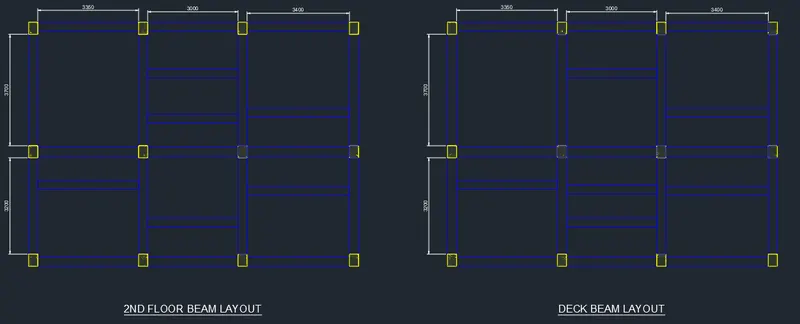
The beam self-weights are as follows:
Beam dimension = 0.3m x 0.45m
B1 = 25 x 3.35 x 0.3 x 0.45 = 11.306 kN (8pcs)
B1 = 25 x 3.0 x 0.3 x 0.45 = 10.125 kN (12pcs)
B1 = 25 x 3.4 x 0.3 x 0.45 = 11.475 kN (10pcs)
B1 = 25 x 3.7 x 0.3 x 0.45 = 12.488 kN (8pcs)
B1 = 25 x 3.2 x 0.3 x 0.45 = 10.8 kN (8pcs)
F.3 Walls
There are two wall thickness, W1 (Denoted by green color) = 0.2m and W2 (Denoted by blue color) = 0.15m.
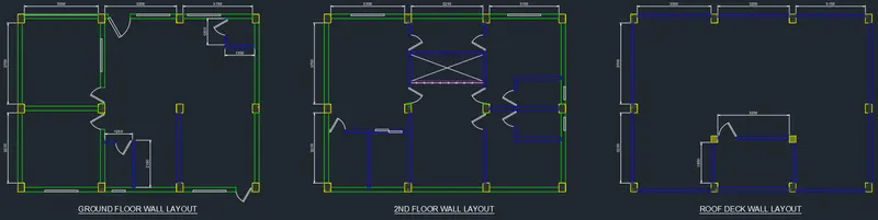
GROUND WALLS
a) Wall 1
Height = 4.0m - 0.45m = 3.55m
Dead Load = 25kN/m3 x 3.55m x 0.2m = 17.75kN/m
Total Length = 3.35x3 + 3.25x2 + 3.15x2 + 3.7x3 + 3.2x3 = 43.55m
Total Weight = 17.75 x 43.55 = 773.01kN
b) Wall 1a
Height = 1.0m
Dead Load = 25kN/m3 x 1.0m x 0.2m = 5.0kN/m
Total Length = 3.35m
Total Weight = 5.0 x 3.35 = 16.75kN
c) Wall 2
Height = 4.0m - 0.45m = 3.55m
Dead Load = 25kN/m3 x 3.55m x 0.15m = 13.3125kN/m
Total Length = 1.25 + 2.15 + 3.2 + 1.2 + 1.35 = 9.15m
Total Weight = 13.3125 x 9.15 = 121.81kN
2ND FLOOR WALLS
a) Wall 1
Height = 3.5m - 0.45m = 3.05m
Dead Load = 25kN/m3 x 3.05m x 0.2m = 15.25kN/m
Total Length = 3.35x2 + 3.25 + 3.15x2 + 3.7x2 + 3.2x2 = 30.05m
Total Weight = 15.25 x 30.05 = 458.2625kN
b) Wall 1a
Height = 1.25m
Dead Load = 25kN/m3 x 1.25m x 0.2m = 6.25kN/m
Total Length = 3.25m
Total Weight = 6.25 x 3.25m = 20.3125kN
c) Wall 2
Height = 3.5m - 0.45m = 3.05m
Dead Load = 25kN/m3 x 3.05m x 0.15m = 11.44kN/m
Total Length = 3.35 + 2.5 + 3.25 + 3.15 + 2.15x2 + 1.225 + 1.25 + 3.7x2 + 3.2x2 = 32.825m
Total Weight = 11.44 x 32.825 = 375.518kN
ROOF DECK WALLS
a) Wall 1
Height = 3.0m - 0.45m = 2.55m
Dead Load = 25kN/m3 x 2.55m x 0.15m = 9.5625kN/m
Total Length = 3.25x2 + 1.85x2 = 10.20m
Total Weight = 9.5625 x 10.02 = 97.5375kN
b) Wall 2
Height = 1.25m
Dead Load = 25kN/m3 x 1.25m x 0.15m = 4.6875kN/m
Total Length = 3.35x2 + 3.25 + 3.15x2 + 3.7x2 + 3.2x2 = 30.05
Total Weight = 4.6875 x 30.05m = 140.86kN
F.4 Slabs
Slab thickness is 200mm. Slab layout is as shown below.
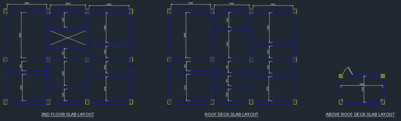
Unit weight of the slab = 25 x 0.2 = 5kN/m2
2ND FLOOR SLABS
Total Area = 3.35x(3.85 + 0.8 + 2.25) + 3.0x(1.25 + 0.8 + 2.05 + 1.0) + 3.4x(2.55 + 1.0 + 1.0 + 2.05) = 60.855m2
Total Weight = 5.0 x 60.855 = 304.275kN
ROOF DECK SLABS
Total Area = 3.35x(3.85 + 0.8 + 2.25) + 3.0x(1.25 + 2.3 + 0.95 + 0.8 + 1.0) + 3.4x(2.55 + 1.0 + 1.0 + 2.05) = 64.455m2
Total Weight = 5.0 x 64.455 = 322.275kN
ABOVE ROOF DECK SLABS
Total Area = 3.55 x 2.25 = 7.9875m2
Total Weight = 5.0 x 7.9875 = 39.9375kN
G. Live Load Calculation
The live loads used in the residential house building is as per Table 1 of IS 875 (Part 2).
| Occupancy Classification | Uniformly Distributed Load (UDL) | Concentrated Load |
| All rooms and kitchens | 2.0 kN/m2 | 1.8 kN |
| Toilet and bath rooms | 2.0 kN/m2 | - |
| Corridors, passages, staircases including fire escapes and store rooms | 3.0 kN/m2 | 4.5 kN |
| Balconies | 3.0 kN/m2 | 1.5 per metre run concentrated at the outer edge |
| Garage floors for vehicles not exceeding 4.0 tonnes gross weight (including access ways and ramps) - to be calculated but not less than | 5.0 kN/m2 | 9.0 kN |
Ground Floor Live Loads
| Location | UDL, kN/m2 | Area, m2 | Total Load, kN |
| Garage | 5.0 | 14.7325 | 73.66 |
| Guest Room | 2.0 | 12.425 | 24.85 |
| Toilet | 2.0 | 2.5 | 5.00 |
| Meditation Room | 2.0 | 1.44 | 2.88 |
| Living Room | 2.0 | 13.94 | 27.88 |
| Dining Room | 2.0 | 12.5 | 25.00 |
| Kitchen | 2.0 | 12.78 | 25.56 |
| Stair Location | 3.0 | 9.2 | 27.60 |
2nd Floor Live Loads
| Location | UDL, kN/m2 | Area, m2 | Total Load, kN |
| Master's Bedroom | 2.0 | 18.18 | 36.36 |
| Toilet | 2.0 | 4.25 | 8.5 |
| W.I.C. | 2.0 | 4.25 | 8.5 |
| Balcony | 3.0 | 4.0625 | 12.19 |
| Hallway | 3.0 | 15.7625 | 47.29 |
| Toilet 1 | 2.0 | 2.5 | 5.0 |
| Bedroom 1 | 2.0 | 11.185 | 22.37 |
| Toilet 2 | 2.0 | 2.5 | 5.0 |
| Bedroom 2 | 3.0 | 9.485 | 28.46 |
Roof Deck Live Loads
| Location | UDL, kN/m2 | Area, m2 | Total Load, kN |
| Deck Area | 2.0 | 83.07 | 166.14 |
| Stair Location | 3.0 | 7.81 | 23.43 |
H. Wind Load Calculation
In this residential building, the effective height that will be used is 8.75m. Although the highest point of the house is at 10.5m because of the shed structure above the roof deck, the effective height will still be 8.75m. To accomodate this height, the design wind pressure will not be reduced by 20% as described in the code.
H.1 Design Wind Speed (Vz)
The wind load is applied on all sides of the building. Wind loads are applied for evaluating structure stability and design of the framing.
a) Wind Load Parameters
Basic Wind Speed (Vb) = 39m/s
Return Period = 50 years
Risk Coefficient (k1) = 1.0 (Table 1 of IS 875 Part 3:2015)
Terrain = Category 2
Effective Height of Building = 8.75m and 10.5; use 10m to determine Coefficient values
Terrain Height Factor (k2) = 1.0 (Table 2 of IS 875 Part 3:2015)
Topography Factor (k3) = 1.0 (Clause 6.3.3 of IS 875 Part 3:2015)
Importance Factor for Cyclonic Region (k4) = 1.0 (Clause 6.3.4 of IS 875 Part 3:2015)
b) Design Wind Speed (Vz)
Vz = Vb x k1 x k2 x k3 x k4
= 39 x 1.0 x 1.0 x 1.0 x 1.0
Vz = 39 m/s
c) Wind Pressure at height z (Pz)
Pz = 0.6 Vz^2
= 0.6 x 39^2
Pz = 912.6 N/m^2
d) Design Wind Pressure (Pd)
Design Wind Pressure, Pd = Kd x Ka x Kc x Pz
Wind Directionality Factor (Kd) = 0.90 - For Buildings
Tributary Area of the Building (For Overall Structure) = Max(Length,Width) x Height
= Max(10.95m,8.1m) x 8.75m
Tributary Area of the Building = 10.95 x 8.75 x 1/2 = 47.91 m^2
Area Averaging Factor (Ka) = 0.9 (Table 4 of IS 875 Part 3:2015)
Combination Factor (Kc) = 1.0 (Clause 7.3.3.13 of IS 875 Part 3:2015)
Design Wind Pressure, Pd = 0.9 x 0.9 x 1.0 x 912.6 = 739.206 N/m^2
0.7 Pz = 0.7 x 653.4 = 457.38 N/m^2 < 739.206 N/m^2 ;
Use Pd = 739.206 N/m^2
e) Wind Load on Individual Members
Wind Load will be calculated for X-Direction and Y-Direction.
Height of the structure = 8.75m
Length of the structure = 10.95m
Width of the structure = 8.1m
X-Direction = Wind along East/West Direction
Y-Direction = Wind along North/South Direction
Wind Load, F = (Cpe - CPi) A Pd
e.1 External Pressure Coefficient, Cpe (Table 5 of IS 875 (Part 3):2015)
l = longer side ; w = shorter side ; h = height of building
Building Height Ratio, h/w = 8.75/8.1 = 1.08 ; 1/2 < h/w <= 3/2
Building Plan Ratio, l/w = 10.95/8.1 = 1.35 ; 1 <= l/w <= 3/2
Cpe Coefficients are as follows:
Wind Load at X-Direction (Wind Angle = 0 degrees)
| Surface | A | B | C | D |
| Cpe | +0.7 | -0.25 | -0.6 | -0.6 |
Wind Load at Y-Direction (Wind Angle = 90 degrees)
| Surface | A | B | C | D |
| Cpe | -0.6 | -0.6 | +0.7 | -0.25 |
Local Cpe for both cases are -1.1.
e.2 Internal Pressure Coefficient, Cpi (Clause 7.3.2.1 and 7.3.2.2 of IS 875 (Part 3):2015)
Opening Type of Building = Medium openings between about 5% to 20% of Wall Area
Cpi = (+,-) 0.5
e.3 Wind Load on Each Surface
Length for Local surface area = 0.25W
For Cpi, critical condition is applied.
h) Wind Load on Structure
h.1 Wind Load at X-Direction (Wind Angle = 0 degrees)
Structure below 8.75m
| Surface | Length, m | Height, m | Cpe | Cpi | Area, m^2 | Pd, N/m^2 | F, kN |
| A | 8.1 | 8.75 | +0.7 | -0.5 | 70.875 | 739.209 | 60.318 |
| B | 8.1 | 8.75 | -0.25 | +0.5 | 70.875 | 739.209 | -37.699 |
| C - Local | 2.025 | 8.75 | -1.1 | +0.5 | 17.719 | 739.209 | -20.106 |
| C | 8.925 | 8.75 | -0.6 | +0.5 | 78.094 | 739.209 | -60.923 |
| D - Local | 2.025 | 8.75 | -1.1 | +0.5 | 17.719 | 739.209 | -20.106 |
| D | 8.925 | 8.75 | -0.6 | +0.5 | 78.094 | 739.209 | -60.923 |
Structure above 8.75m
| Surface | Length, m | Height, m | Cpe | Cpi | Area, m^2 | Pd, N/m^2 | F, kN |
| A | 2.55 | 1.5 | +0.7 | -0.5 | 3.825 | 739.209 | 3.255 |
| B | 2.55 | 1.5 | -0.25 | +0.5 | 3.825 | 739.209 | -2.035 |
| C - Local | 0.6375 | 1.5 | -1.1 | +0.5 | 0.956 | 739.209 | -1.085 |
| C | 3.2125 | 1.5 | -0.6 | +0.5 | 4.819 | 739.209 | -3.759 |
| D - Local | 0.6375 | 1.5 | -1.1 | +0.5 | 0.956 | 739.209 | -1.085 |
| D | 3.2125 | 1.5 | -0.6 | +0.5 | 4.819 | 739.209 | -3.759 |
h.2 Wind Load at Y-Direction (Wind Angle = 90 degrees)
Structure below 8.75m
| Surface | Length, m | Height, m | Cpe | Cpi | Area, m^2 | Pd, N/m^2 | F, kN |
| A - Local | 2.025 | 8.75 | -1.1 | +0.5 | 17.719 | 739.209 | -20.106 |
| A | 6.075 | 8.75 | -0.6 | +0.5 | 53.156 | 739.209 | -41.469 |
| B - Local | 2.025 | 8.75 | -1.1 | +0.5 | 17.719 | 739.209 | -20.106 |
| B | 6.075 | 8.75 | -0.6 | +0.5 | 53.156 | 739.209 | -41.469 |
| C | 10.95 | 8.75 | +0.7 | -0.5 | 95.813 | 739.209 | 81.541 |
| D | 10.95 | 8.75 | -0.25 | +0.5 | 95.813 | 739.209 | -50.963 |
Structure above 8.75m
| Surface | Length, m | Height, m | Cpe | Cpi | Area, m^2 | Pd, N/m^2 | F, kN |
| A - Local | 0.6375 | 1.5 | -1.1 | +0.5 | 0.956 | 739.209 | -1.085 |
| A | 1.9125 | 1.5 | -0.6 | +0.5 | 2.869 | 739.209 | -2.238 |
| B - Local | 0.6375 | 1.5 | -1.1 | +0.5 | 0.956 | 739.209 | -1.085 |
| B | 1.9125 | 1.5 | -0.6 | +0.5 | 2.869 | 739.209 | -2.238 |
| C | 3.85 | 1.5 | +0.7 | -0.5 | 5.775 | 739.209 | 4.915 |
| D | 3.85 | 1.5 | -0.25 | +0.5 | 5.775 | 739.209 | -3.072 |
I. Seismic Load Calculation
I.1 Seismic Parameters
Height of structure considered = 8.75m
Natural Period of Vibration, Ta = 0.075 * 8.75^0.75 = 0.38seconds
Zone Factor, Z = 0.10 (Zone II)
Importance Factor, I = 1.0
Response Reduction Factor, R = 3.0
Average response acceleration coefficient, Sa/g = 2.5
I.2 Calculation of Horizontal Seismic Coefficient, Ah
Ah = (Z * I * Sa/g) / 2R
Ah = 0.1 * 1.0 * 2.5 / (2*3.0) = 0.0417
I.3 Calculation of Total Weight and Imposed Dead Load
a) Ground Floor Weight
Dead Load
a.1 Column Weight = 0.3 x 0.4 x 4.0 x 25 x 12 = 144kN
a.2 Wall Weight = 773.01 + 16.75 + 121.81 = 911.57kN
Imposed Load
Total Ground Floor Live Load = 0.5x73.66 + 0.25x(24.85 + 5.0 + 2.88 + 27.88 + 25.0 + 25.56 + 27.6) = 71.5225kN
Total Weight, W1 = 144 + 911.57 + 71.5225 = 1127.0925kN
b) 2nd Floor Weight
Dead Load
a.1 Column Weight = 0.3 x 0.4 x 3.5 x 25 x 12 = 126kN
a.2 Wall Weight = 458.2625 + 20.3125 + 375.518 = 854.093kN
a.3 Beam Weight = 11.306x4 + 10.125x6 + 11.475x5 + 12.488x4 + 10.8x4 = 256.501kN
a.4 Slab Weight = 304.275kN
Imposed Load
Total Ground Floor Live Load = 0.25x(36.36 + 8.5 + 8.5 + 12.19 + 47.29 + 5.0 + 22.37 + 5.0 + 28.46 ) = 43.415kN
Total Weight, W2 = 126 + 854.093 + 256.501 + 304.275 + 43.415 = 1584.284kN
c) Roof Deck Floor Weight
Dead Load
a.1 Column Weight = 25 x [(0.3 x 0.4 x 1.25 x 8) + (0.3 x 0.4 x 3.0 x 2) + (0.3 x 0.3 x 3.0 x 2)] = 61.5kN
a.2 Wall Weight = 97.5375 + 140.86 = 238.3975kN
a.3 Beam Weight = 11.306x4 + 10.125x6 + 11.475x5 + 12.488x4 + 10.8x4 = 256.501kN
a.4 Slab Weight = 322.275 + 39.9375 = 362.2125kN
Imposed Load
Total Ground Floor Live Load = 0.25x(166.14 + 23.43 ) = 47.3925kN
Total Weight, W3 = 61.5 + 238.3975 + 256.501 + 362.2125 + 47.3925 = 966.0035kN
Total Weight of Structures:
Ground Floor, W1 = 1127.0925kN
2nd Floor, W2 = 1584.284kN
Roof Deck, W3 = 966.0035kN
Total Weight of Structure, W = 1127.0925 + 1584.284 + 966.0035 = 3677.38kN
I.4 Calculation of Base Shear
VB = W x Ah = 0.0417 x 3677.38
VB = 153.35kN
I.5 Calculation of Design Forces per Level
| Mark | Weight, kN | height, m | Wi * hi^2 | VB, kN | Qi, kN |
| Ground Level | 1127.0925 | 4.0 | 18033.48 | 153.35 | 59.94kN |
| 2nd Floor Level | 1584.284 | 3.5 | 19407.48 | 153.35 | 64.51kN |
| Roof Deck Level | 966.0035 | 3.0 | 8694.032 | 153.35 | 28.90kN |
Total of Wi*hi^2 = 46134.99
*************************************************
IV. RESULTS SUMMARY
J. Summary of Results
J.1 Dead Load
J.1.1 Columns
C1 = 25 x 8.75 x 0.3 x 0.4 = 26.25 kN (9pcs)
C2 = 25 x 10.5 x 0.3 x 0.4 = 31.5 kN (2pcs)
C3 = 25 x 3.0 x 0.3 x 0.3 = 6.75 kN (2pcs)
J.1.2 Beams
B1 = 25 x 3.35 x 0.3 x 0.45 = 11.306 kN (8pcs)
B2 = 25 x 3.0 x 0.3 x 0.45 = 10.125 kN (12pcs)
B3 = 25 x 3.4 x 0.3 x 0.45 = 11.475 kN (10pcs)
B4 = 25 x 3.7 x 0.3 x 0.45 = 12.488 kN (8pcs)
B5 = 25 x 3.2 x 0.3 x 0.45 = 10.8 kN (8pcs)
J.1.3 Walls
a. Ground Walls
GW1 = 17.75kN/m
GW1a = 5.0kN/m
GW2 = 13.3125kN/m
b. 2nd Floor Walls
2W1 = 15.25kN/m
2W1a = 6.25kN/m
2W2 = 11.44kN/m
c. Roof Deck Walls
RW1 = 9.5625kN/m
RW2 = 4.6875kN/m
J.1.4 Slabs
Slab unit weight per area = 5kN/m2
2ND FLOOR SLABS
Total Area = 60.855m2
Total Weight = 304.275kN
ROOF DECK SLABS
Total Area = 64.455m2
Total Weight = 322.275kN
ABOVE ROOF DECK SLABS
Total Area = 7.9875m2
Total Weight = 39.9375kN
J.2 Live Load
Ground Floor Live Loads
| Location | UDL, kN/m2 | Area, m2 | Total Load, kN |
| Garage | 5.0 | 14.7325 | 73.66 |
| Guest Room | 2.0 | 12.425 | 24.85 |
| Toilet | 2.0 | 2.5 | 5.00 |
| Meditation Room | 2.0 | 1.44 | 2.88 |
| Living Room | 2.0 | 13.94 | 27.88 |
| Dining Room | 2.0 | 12.5 | 25.00 |
| Kitchen | 2.0 | 12.78 | 25.56 |
| Stair Location | 3.0 | 9.2 | 27.60 |
2nd Floor Live Loads
| Location | UDL, kN/m2 | Area, m2 | Total Load, kN |
| Master's Bedroom | 2.0 | 18.18 | 36.36 |
| Toilet | 2.0 | 4.25 | 8.5 |
| W.I.C. | 2.0 | 4.25 | 8.5 |
| Balcony | 3.0 | 4.0625 | 12.19 |
| Hallway | 3.0 | 15.7625 | 47.29 |
| Toilet 1 | 2.0 | 2.5 | 5.0 |
| Bedroom 1 | 2.0 | 11.185 | 22.37 |
| Toilet 2 | 2.0 | 2.5 | 5.0 |
| Bedroom 2 | 3.0 | 9.485 | 28.46 |
Roof Deck Live Loads
| Location | UDL, kN/m2 | Area, m2 | Total Load, kN |
| Deck Area | 2.0 | 83.07 | 166.14 |
| Stair Location | 3.0 | 7.81 | 23.43 |
J.3 Wind Load
J.3.1 Wind Load at X-Direction
Structure below 8.75m
| Surface | F, kN |
| A | 60.318 |
| B | -37.699 |
| C - Local | -20.106 |
| C | -60.923 |
| D - Local | -20.106 |
| D | -60.923 |
Structure above 8.75m
| Surface | F, kN |
| A | 3.255 |
| B | -2.035 |
| C - Local | -1.085 |
| C | -3.759 |
| D - Local | -1.085 |
| D | -3.759 |
J.3.2 Wind Load at Z-Direction
Structure below 8.75m
| Surface | F, kN |
| A - Local | -20.106 |
| A | -41.469 |
| B - Local | -20.106 |
| B | -41.469 |
| C | 81.541 |
| D | -50.963 |
Structure above 8.75m
| Surface | F, kN |
| A - Local | -1.085 |
| A | -2.238 |
| B - Local | -1.085 |
| B | -2.238 |
| C | 4.915 |
| D | -3.072 |
J.4 Seismic Load
Base Shear, VB = 153.35kN
Design Seismic Forces are as follows
| Mark | Qi, kN |
| Ground Level | 59.94kN |
| 2nd Floor Level | 64.51kN |
| Roof Deck Level | 28.90kN |
*************************************************
V. CONCLUSION
We can see that the residential of this magnitude delivers a heavy load. The structure itself needs to be heavy so that horizantal forces such as earthquakes or wind loads will not overturn the structure. We can observe that in the calculation, seismic forces are bigger than wind load. In this case, the seismic load will govern in the design. When the design is conducted, a series of load combinations are provided where the dead load, live load, and seismic loads (or wind loads) are applied together on the structure. These load combinations are based from IS 456:2000 Table 18 Values of Partial Safety Factor yt for Loads. The residential house building will be designed according to these load combinations and load calculations. The structure must withstand these loads to provide safety for the people that will reside within the house.
We can also see that the Vaastru Shastra concept is applied in the residential building. This will provide prosperity, wealth, and good health to the familt that will live inside the house. Other Vaastru Shastra concept should also be followed by the tenants to further increase the good energy flowing in the house.