Project 2_Creating a 3D rendered model for a Residential Building in AutoCad
AIM :
Create a 3 dimensional model of the residential building with a rendered view.
INTROUCTION :
RENDERING :
Rendering is the process of creating a raster image based on the 3D objects in a scene. A renderer is used to calculate the appearance of the materials attached to the objects in a scene, and how lighting and shadows are calculated based on the lights placed in a scene. Environmental and exposure settings of the renderer can be adjusted to control the final rendered image.
While the final goal of rendering is to create an artistic or photorealistic presentation-quality image, you might need to create many renderings before you reach that goal. The basic rendering workflow is to attach materials to the 3D objects of a model, place user-defined lights, add a background, and start the renderer with the RENDER command.
A rendered image can be created for a new model without attaching materials, placing user-defined lights, and adding a background. By default, a default material is added to all 3D objects in a model and the renderer automatically uses two default distant lights when user-defined lights are not placed in a scene. As an alternative to the two default distant lights, you can specify the use a single default distant light that shines from over-the-shoulder. Default lights cannot be moved or adjusted.
| Task | Related Commands |
|---|---|
| 1. Create a 3D model containing the objects to be rendered with 3D solids, surfaces, meshes, and 3D faces. | 3DFACE, 3DMESH, BOX, CONE, CYLINDER, EDGESURF, EXTRUDE, LOFT, MESH, PFACE, PLANESURF, POLYSOLID, PRESSPULL, PYRAMID, REVOLVE, REVSURF, RULESURF, SPHERE, SURFBLEND, SURFNETWORK, SURFOFFSET, SURFPATCH, SWEEP, TABSURF, TORUS, WEDGE |
| 2. Define the views of the 3D model to render.
Use named views for consistency and to make switching views easier. |
VIEW |
| 3. Assign a background to the current view. | BACKGROUND, VIEW |
| 4. Create materials to be attached to 3D objects. | MATBROWSEROPEN, MATEDITOROPEN |
| 5. Attach materials to 3D objects directly or by layer. | MATERIALASSIGN, MATERIALATTACH |
| 6. Add user-defined lights or use default lighting.
Note: The LIGHTINGUNITS system variable must be set to 1 or 2.
Enable image-based lighting as an alternative to default lighting, or to fill an entire scene with light and eliminate dark areas. |
DISTANTLIGHT, FREESPOT, FREEWEB, LIGHT, POINTLIGHT, SPOTLIGHT, TARGETPOINT, WEBLIGHT, RENDEREXPOSURE |
| 7. Optionally, enable and define settings for the Sun & Sky based lighting when rendering indoor or outdoor architectural scenes.
Note: The LIGHTINGUNITS system variable must be set to 1 or 2.
|
SUNPROPERTIES |
| 8. Set the Low render preset current. | RENDERPRESETS |
| 9. Render a region of the 3D model to test the attached materials and lighting. | RENDERCROP |
| 10. Adjust the materials and lighting in the scene based on the results of the test rendering. | |
| 11. Set the rendering environment and exposure settings. | RENDEREXPOSURE |
| 12. Create another test rendering; make any desired changes to the materials, lighting, and general rendering environment settings. | |
| 13. Set a render preset with the best rendering quality desired current and create the final rendered image. | RENDER, RENDERPRESETS |
| 14. Save the rendered image to a raster image file. | RENDER, SAVEIMG |
PROCEDURE :
Step by Step procedure to create a 3 dimensional model of the residential building with a rendered view
1. Draw the plan of the Residential building.
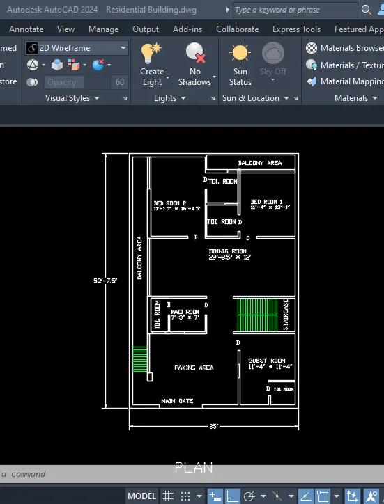
2. Draw the Elevation of the Residential building (Front Side).
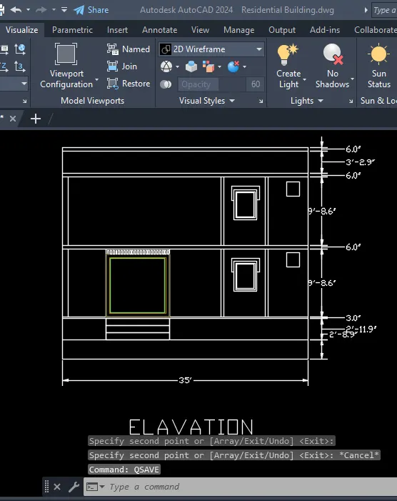
3. Enter BOUNDARY(BO) command: BO [Enter]
4. Draw the Window
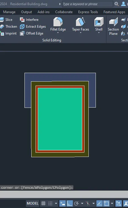
5. Extrude the Window
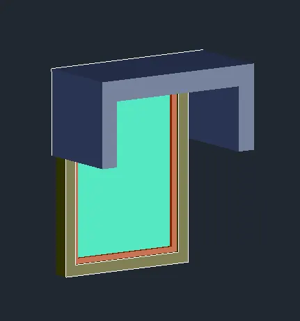
6. Draw the Door
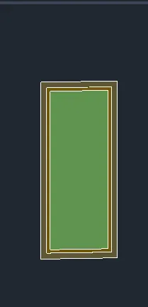
6. Extrude the Door
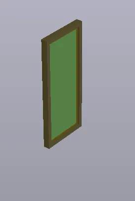
7. Draw and Extrude the Main Door
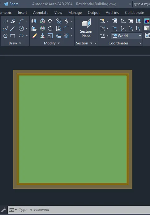
8. Extrude the 9" Walls & 4.5" Walls (Height - 3'-3")
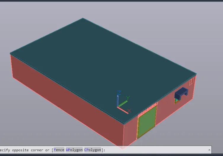
9. Enter the UCS command : UCS[Enter]
10. Click on Face than & then select the face of top of the outside wall
11. Enter RECTANGULAR command : REC[Enter]
12. Enter BOUNDARY(BO) command: BO [Enter]
13. Enter Height : 6" [Enter]
14. First floor slab is completed
15. Enter the UCS command : UCS[Enter]
16. Click on Face than & then select the face of top of the outside wall on first floor slab
17. Now copy the plan of the residential building the outside wall on first floor slab and extrude to height (3'-3")
18. Now complete the 3D model of residential building
19. Enter light command : DISTANTLIGHT[Enter]
20. Enter Material browser command : MATBROWSEROPEN[Enter]
21. Assign property on the wall, slab, projection, Door, Windows etc from Material browser.
22. Enter Rendering command : RR[Enter]
A complete 3 dimensional model of the residential building with a rendered view
RESULT :
A 3 dimensional model of the residential building with a rendered view
1. Snipping Image of one storey rendered residential building
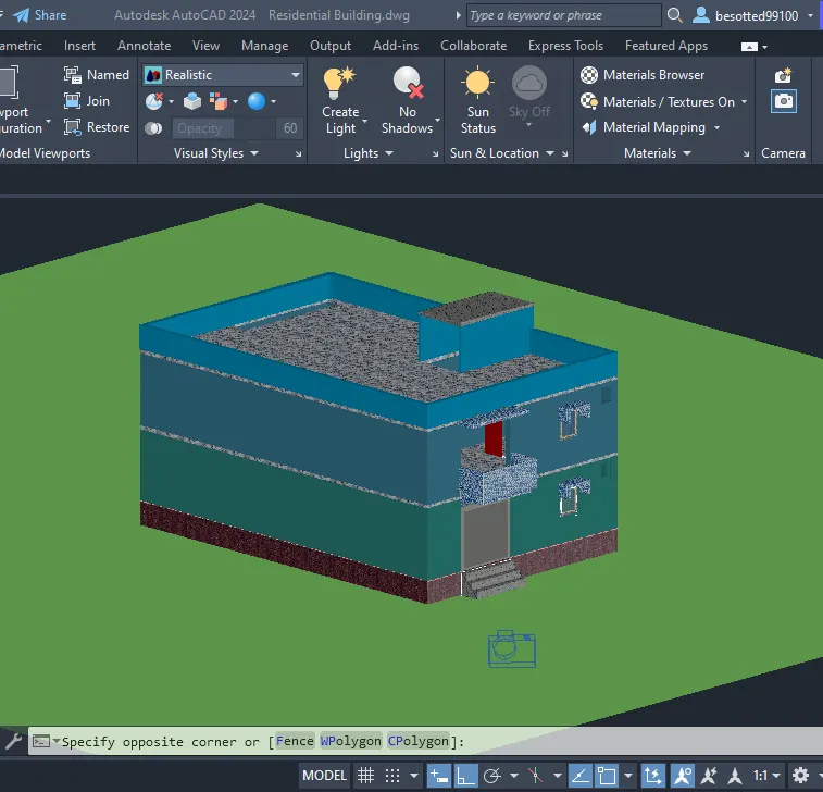
2. Rendering Image of one storey residential building (Material browser)
In the documents