Project 2_Creating a 3D rendered model for a Residential Building in AutoCad
Project_2 - Create a 3 dimensional model of the residential building with a rendered view.
AIM:
- To create the 3 dimensional model of the residential building with arendered view
INTRODUCTION:
AutoCAD 3D is a three dimensional computer aided design, is technology for design and technical documentation, which replaces manual drafting with an automated process
Types of 3D models,
- Wireframe models
- Surface models
- Solid models
Command tools:
2D tools - LINE, RECTANGLE, OFFSET, TRIM, CIRCLE, ERASE, COPY, MOVE, LAYERS, MIRROR, EXTEND, ROTATE, DIMENSION, TEXT, FILLET, JOIN
3D tools - BOUNDARY, REGION, EXTRUDE, SUBTRACT, REVOLVE, SWEEP, UNION
RENDERING - Rendering is the process of creating a raster image based on the 3D objects in a scene. A render is used to calculate the appearance of the materials attached to the objects in a scene, and how lighting and shadows are calculated based on the lights placed in a scene.
PROCEDURE:
Starting a AutoCAD software:
- Open Autocad software and click on START DRAWING.
- Set the units and length type by using 'UNITS' command.
- Set the limits by using 'LIMITS' command.
- Using 'ZOOM' command and select 'All' option
- Switch to 3D modelling on workspace.
Step 1:
- First to create a plan for the 3D model
- Start a new layout and set the limits, units
- Draw a outer wall 9" and inner wall 4.5"
- Draw ground floor and first floor walls
- Using LINE, OFFSET, TRIM command to create the walls
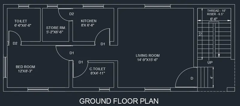
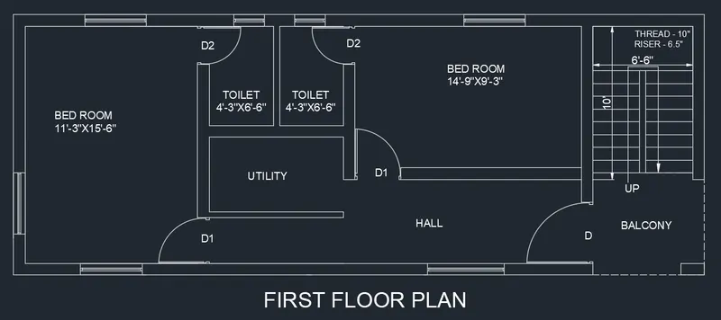
Step 2:
- EXTRUDE the plan and subtract the doors and windows spaces
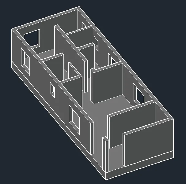
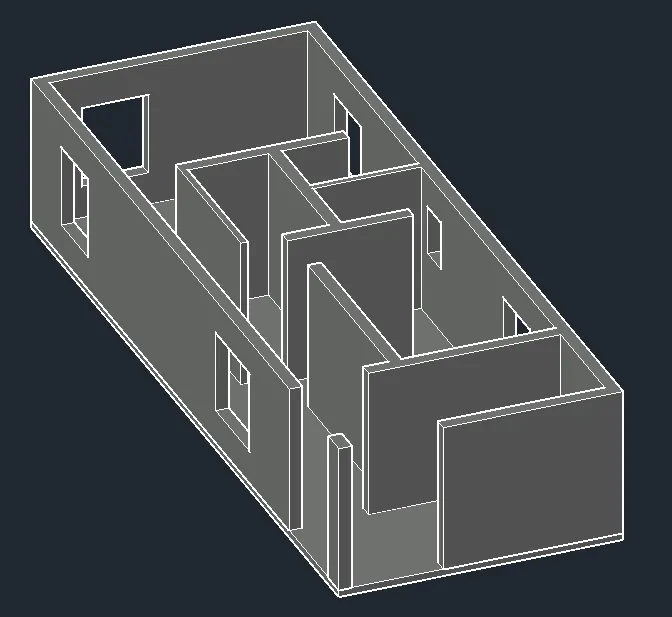
Step 3:
- Create the steps at what you assumed dimensions
- EXTRUDE the objects
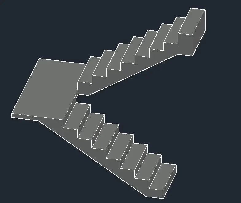
Step 4:
- Create the floor, plinth beam, parapet wall
- SUBTRACT the stair case spaces in beam
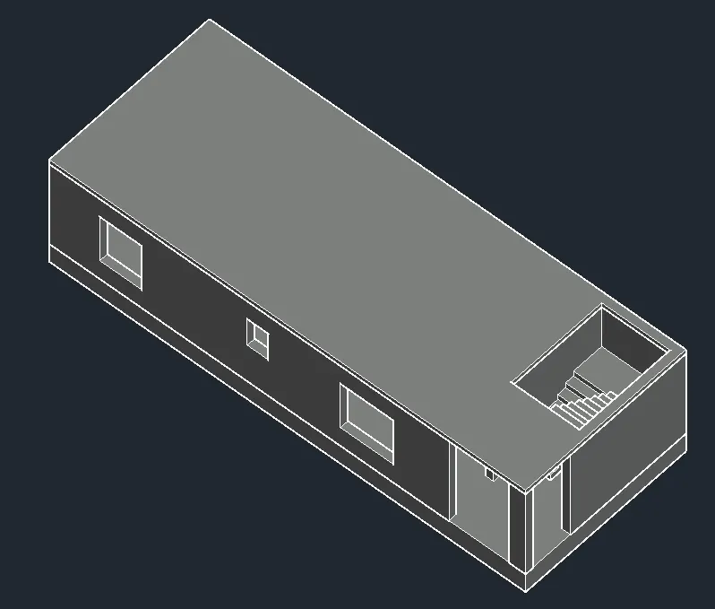
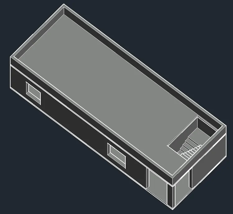
Step 5:
- Make a alignment in proper way
- Create the doors and windows in assumed sizes
- Create the balcony anddraw the design for supported object
- Create the sunshade using LOFT option
- Create the compund wall and steel gate
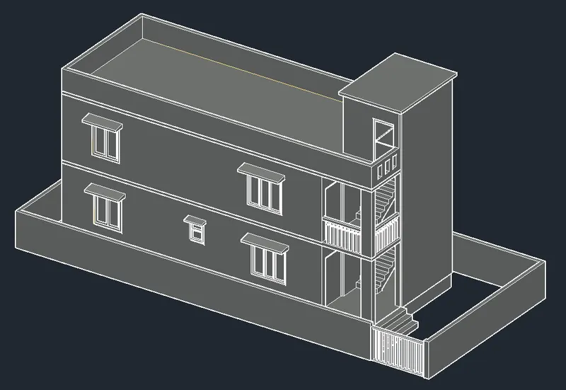
Step 6:
- Create the LAYERS for each object
- And make the colours option to given the layers
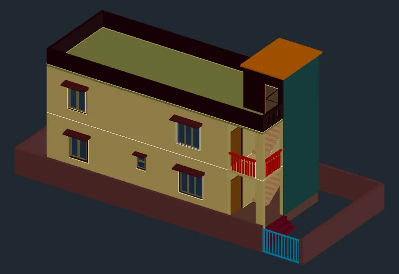
Step 7:
- Create the rectangle and place the drawing above of the rectangle
- EXTRUDE the rectangle and what we want size
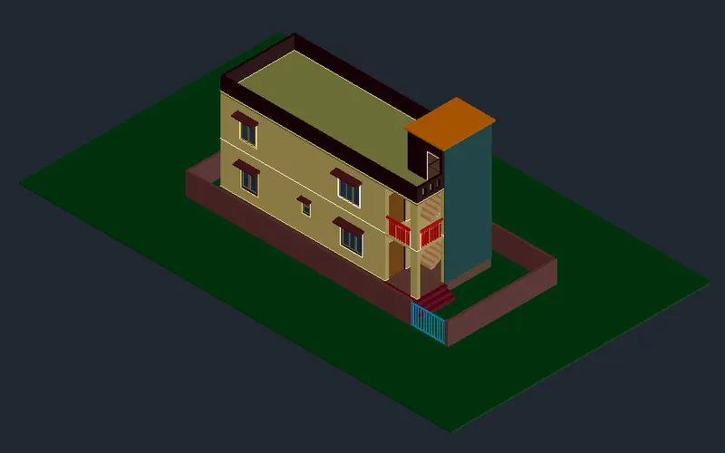
Step 8:
- Go to visualize in ribbon tab
- And given the material in each object
- Such as window, door, stairs, steps, compund wall, main gate, balcony, roof, parapet wall, walls, floor
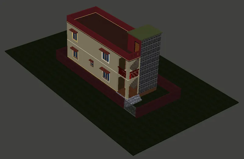
RESULT: