Creation of Multiple viewports, Scaling the drawing and setting in Template in AutoCad
QUESTION:
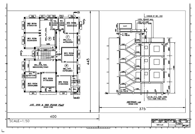
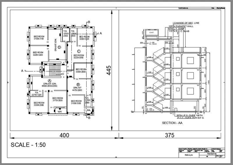
1. Create a layout of the Plan and Section A of the project in Challenges 7, using the template Tutorial-mArch.dwt in a scale as given in the Figure. Use the MV command to create the viewport of the size as shown in Figure. Also, use ATTEDIT command to edit the information in the title block. Use A1 size for the layout. Take a plot.
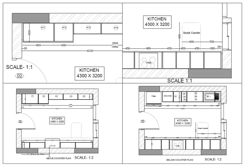
2. Create a layout of the Kitchen drawn in Challenge 9 as shown in Figure. Use the scale as shown in the Figure. Use A4 Size page for the layout. Take a plot.
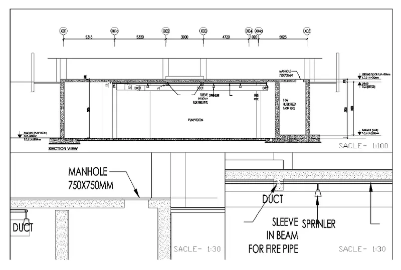
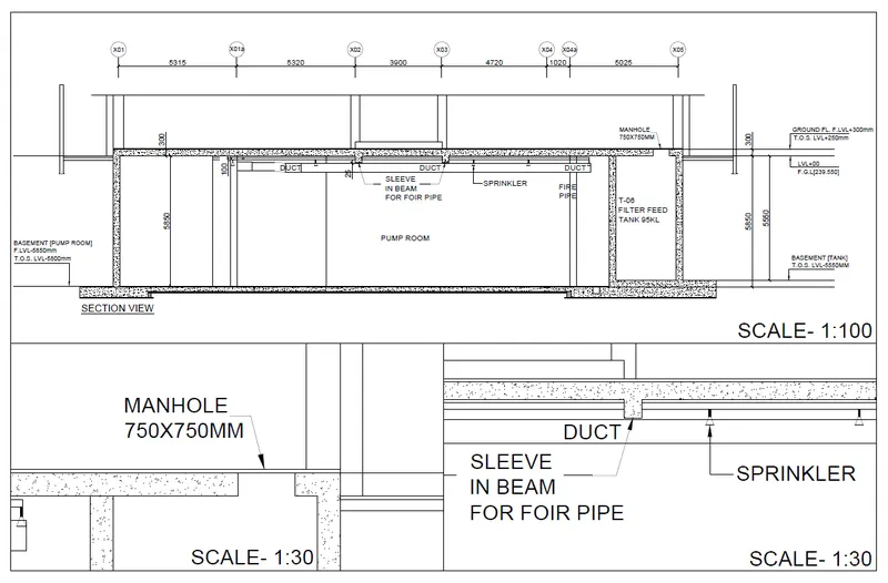
3. Create a layout of the section created in Challenges 9.Use scale as mentioned in the Figure. Use MV command create multiple viewports. Take a plot.
AIM:
(A) To create a layout of the Plan and Section A of the project in Challenges 7
(B) To create a layout of the Kitchen drawn in Challenge 9
(C) To create a layout of the section created in Challenges 9
INTRODUCTION:
- LAYOUT is a 2D working environment for creating drawing sheets
- VIEWPORTS command creates and controls views of your drawing from a layout
- MULTIPLE VIEW 'MV' command is select object option and click on the rectangle, then the drawing will be displayed in the viewport
- MODEL SPACE is an area in which you create 2d and 3d entities based on either the world coordinate system or User coordinate system
- PAPER SPACE is to create paper space page you must set the tilemode variable to 0
- Xref(External reference) is the feature allows you to attach external reference to your drawing
PROCEDURE:
1. Create a layout of the Plan and Section A of the project in Challenges 7:
Step 1:
- Start a new drawing and set the limits and units
- Use XREF command to attach the dwg
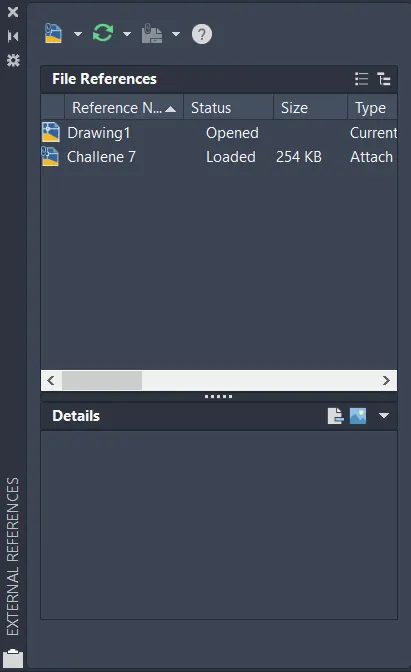
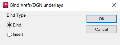
- Right click to uploaded file and click BIND option
- The Challenge 7 drawings are in same file
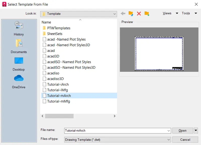
- Go to LAYOUT and right click on any layout, select 'From template' option
- Select Tutorial-mArch template and open
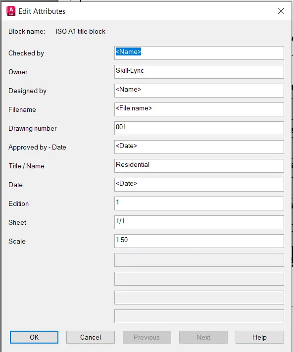
- From the open template edit the Attributes using ATTEDIT command
Step 2:
- Create the rectangle at given dimension from the diagram
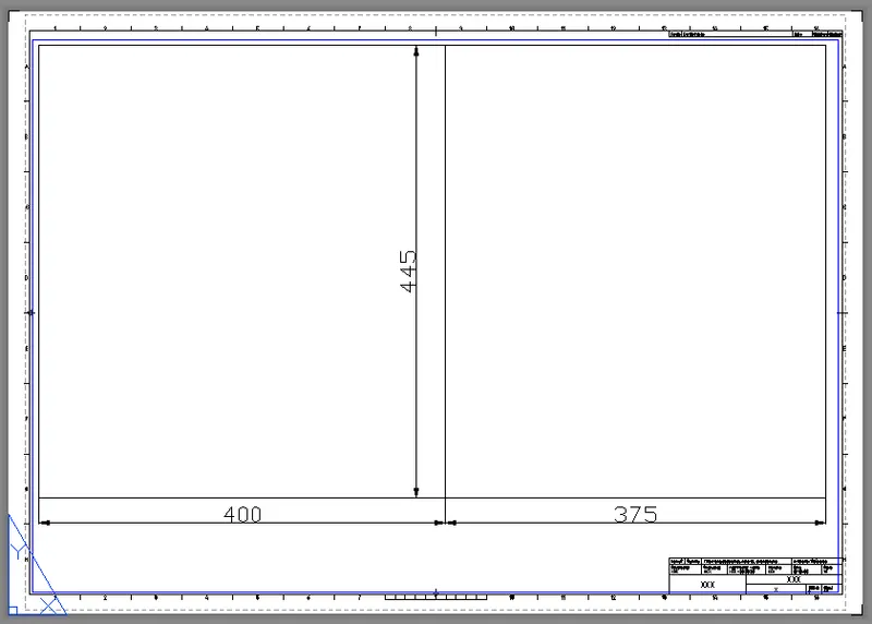
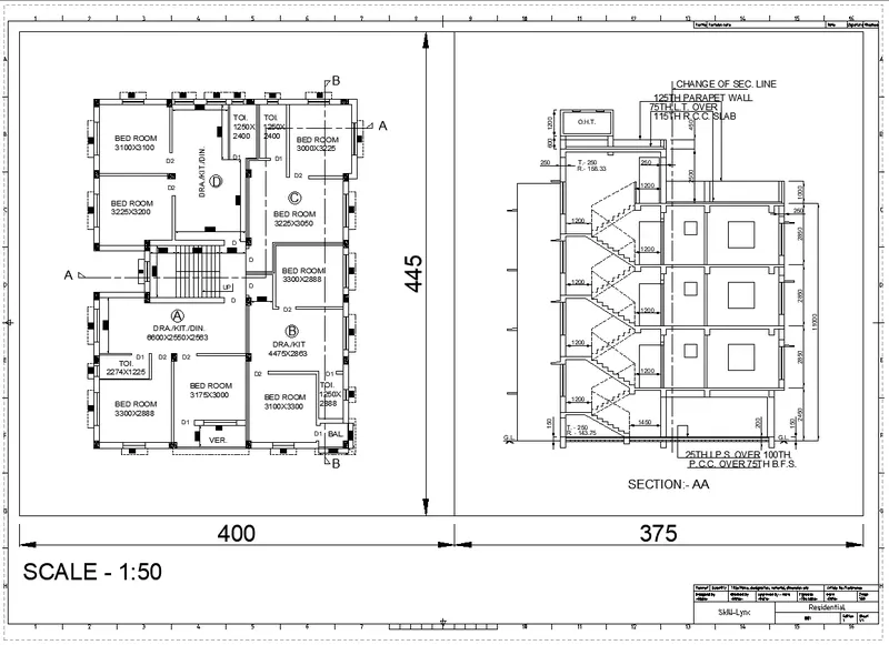
- Use MV multipile view command and select the object to select rectangle
- And set the view at a scale 1:50
- Mention dimensions and scale
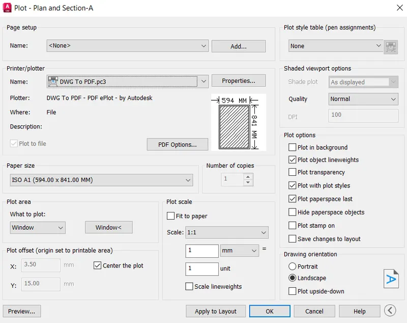
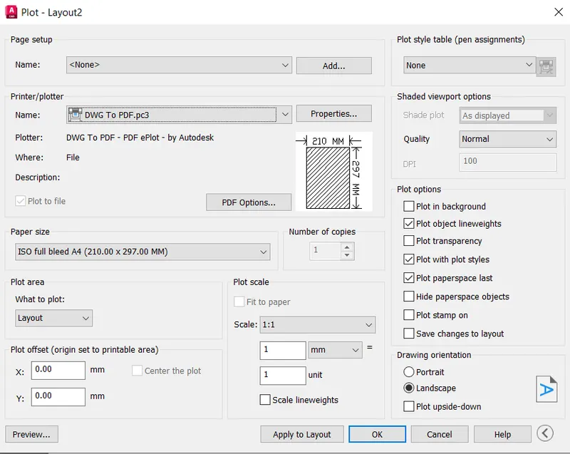
- Use command PLOT the dialog box appears
- Select the option what we want in that dialog box
Result:
2. Create a layout of the Kitchen drawn in Challenge 9:
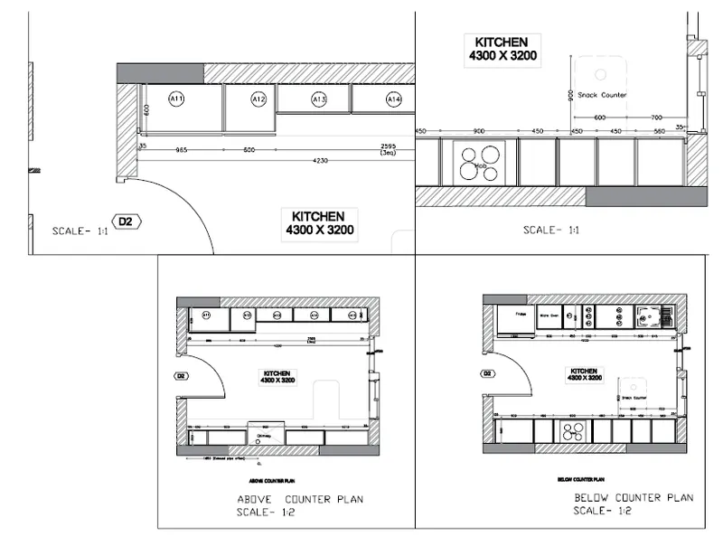
Step 1:
- Start a new diagram and set the limits, units
- Use Xref to attach the kitchen layout dwg
- To change the view ports in four
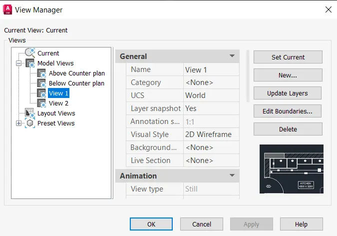
- Use MV command to create the viewport
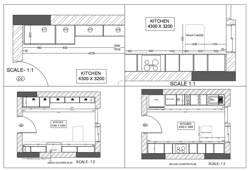
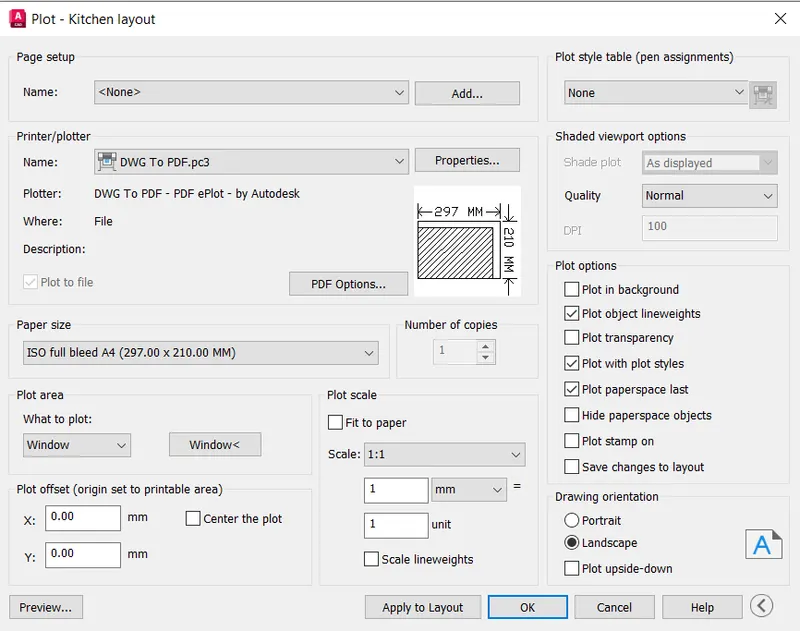
- Use PLOt to convert pdf in A4 size
Result:
3. Create a layout of the section created in Challenges 9:
Step 1:
- Start a new diagram and set the limits, units
- The above two questions same procedure to be followed
- Use Xref to attach the dwg
- Take layout and adjusted what we want
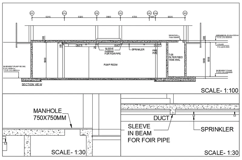
- Take a plot and set the given paper size
Result:
FINAL RESULT:
- Create a Multiple viewports, Scaling the drawing and setting in Template using AutoCAD
- The final diagrams are attached below