Project 1 _Creating an Architectural plan for the provided plot size and develop relevant basic structural drawings
QUESTION:Creating an Architectural plan for the provided plot size and develop relevant basic structural drawings
Design and Draft a layout of a residential building with the following details:
a. Plot Size: 60’x20’(18.3m x6m)
b. Orientation- Facing East
c. Develop the following: 1. Architectural Drawing (Floor Plan, Elevations, and Sections) 2. Structural Drawing (Column, Bean, Footing Plan)
AIM:
To create a design and draft a layout of residential building.
INTRODUCTION:
- Architectural plan are a plan showung the arrangements of proposed building works, elevations and sections.
- Residential building includes all buildings for private occupancy.
PROCEDURE:
Starting a AutoCAD software:
- Open Autocad software and click on START DRAWING.
- Set the units and length type by using 'UNITS' command.
- Set the limits by using 'LIMITS' command.
- Using 'ZOOM' command and select 'All' option
- Use different tools and commands to create a given drawing.
- The above procedure use to given every drawings.
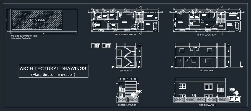
1. ARCHITECTURAL DRAWING:
A) Floor plan:
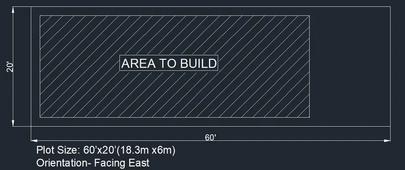
Step 1:
- Start a new layout and set the limits, units
- Create a compound wall 60' and 20'
- Compund wall heigth 5'
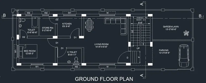
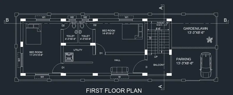
- Draw a outer wall 9" and inner wall 4.5"
- Draw ground floor and first floor walls
- Using LINE, OFFSET, TRIM command to create the walls

Step 2:
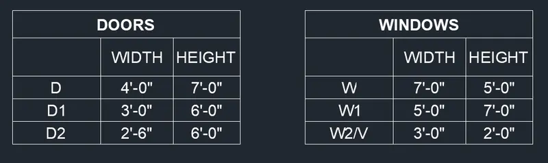
- To draw the doors and windows in two storeys
- Create the text using TEXT option
- And mention the rooms and others
- Using BLOCK option to create the tree, furniture, vehicle and others
B) Sections:
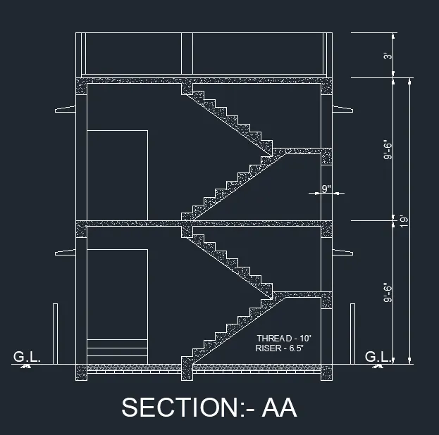
Step 1: Section:- AA
- Using LINE, OFFSET, TRIM to create the section line
- First we draw the section AA
- Provide the doors at assumed sizes
- Draw a stair case ground and first floor
- Draw a window sunshades in the section diagram
- Given the measurements and dimensions
Step 2: Section:- BB
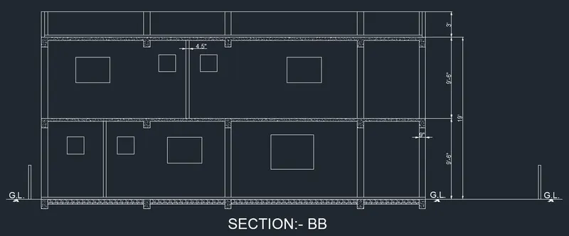
- Using LINE, OFFSET, TRIM to create the section line
- Now we draw the section BB
- Create the floors and draw the columns
- Mention the dimensions
- Place the window at a desired place in section BB
C) Elevations:
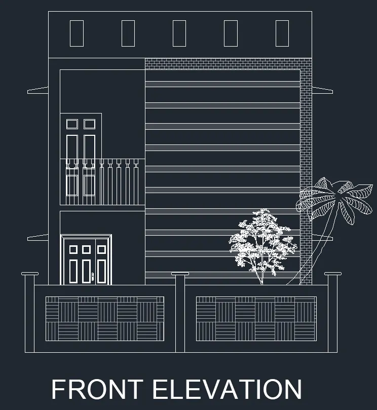
Step 1: Front Elevation
- Draw a front elevation height and width
- Create the doors and balcony
- Create the compound wall at a desired length
- Using BLOCK to set the trees
- Give the design in front wall and parapet wall using HATCH option
- TRIM the unwanted things
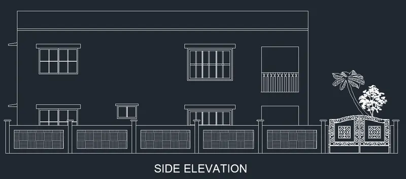
Step 2: Side Elevation
- Create the side elevation at a plan measurements
- Draw the windows and balcony
- Create the compund wall
- Using BLOCK option to create the main iron door and trees
- TRIM the unwanted things
Result:
2. STRUCTURAL DRAWING:
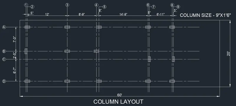
A) Column Layout:
Step 1:
- Using layer to create the plan diagram
- Turn off the layers except column
- Copy and drag the desired place
- Create the boundary at 60'X20'
- Column size is 9"X1'6"
- Using HATCH to fill the column
- Create the center line of each column horizontal and vertical
- The centre line layer is 'long dash short dash'
- Mention the dimension as per required
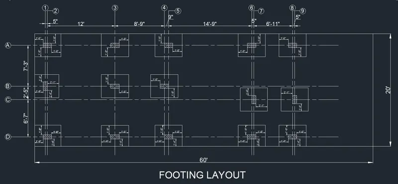
B) Footing Layout:
Step 1:
- Turn off the layer from colum layout except boundary and column
- Using COPY tool to select the object and drag to desired place
- Create the footing as per size of the column
- Turn on the layers and the dimension are mentioned
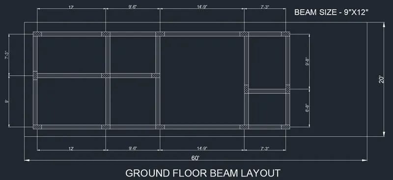
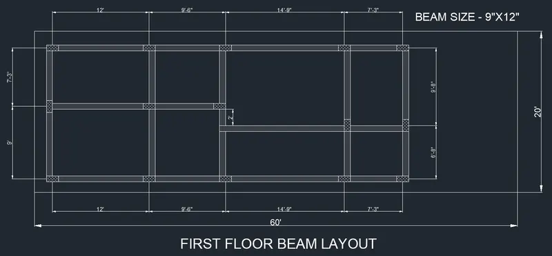
C) Beam Layout:
Step 1:
- Using above same procedure of layer off,copy and drag it
- Create the ground floor beam layout
- At beam size is 9"x12"
- Mentioned the dimension at each column center point
Step 2:
- Next draw the first floor beam layout
- Same above procedure copy and drag the GF beam layout
- Draw the additional at where we want the place
- A beam size is 9"X12"
- Mentioned the dimension at each column center point
Result:
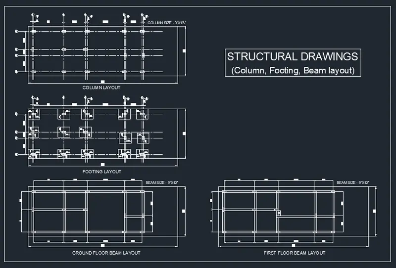
FINAL RESULTS:
- An Architectural plan for the provided plot size and develop relevant basic structural drawings are drafted using AutoCAD
- The final drawings are attached below
ARCHITECTURAL DRAWING:
STRUCTURAL DRAWING: