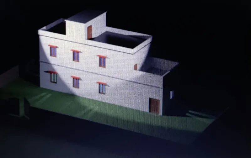
Project 2_Creating a 3D rendered model for a Residential Building in AutoCad
AIM:-
To create a three-dimensional model of the residential building with a rendered view using Autocad.
INTRODUCTION:-
2D wireframe model:-A wireframe model is a skeletal description of a 3d point.There are no surfaces in a wireframe model & it consists of only points, lines & curves that describe the edges of the object.With Autocad one can create wireframe models by positioning 2D objects anywhere in 3D space.
Surface model:-Surface modelling is more sophisticated than wireframe modelling.but also it surfaces.The Autocad surface modeler defines faced surface using a polygonal mesh.
Solid model:-With Autocad solid modeler ,One can make 3d object by creating basic 3d shapes:boxes,spheres,cones & torus One can combine these shapes to create more complex solids by joining or substracting them or finding their intersecting volume.you can alsocreate solids by sweeping a 2d objects along a path or revolving it about an axis.
Rendering:- Rendering is a process of creating a raster image based on the 3d objects in a scene.A rendered image can e created for a new model for a new model without model without attaching materials ,placing,user defined lights,& adding a background.
The assumed dimensions are as following:-
.External wall -230mm
.Internal wall-150mm
Treads-250mm
riser-200mm
.Windows detail-
W-100MMX1500MM
V-700MMX500MM
Door dimensions-
D-1500X2000 MM
D2-1000X2000 MM
D3-900X2000MM
.Beam size-230x350mm
Column size-230x230mm
PROCEDURE:-
.Open Autocad application
.In start up setting start from scratch select metrics.
.Type 'UN'& press enter.
.Set the units to scale inserted content as 'milimeter' & press enter.
.Set limits by typing limits in the command box.
.Change the workspace setting of AutoCAD from drafting & annotation to 3d modelling.
STEP1:-
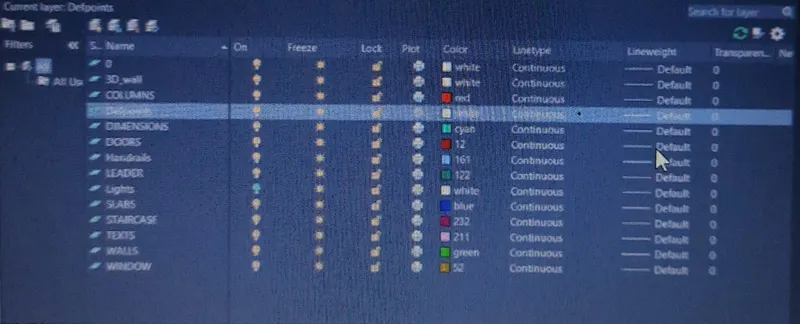
.Type 'LA' in the command box & press enter.
.In layer properties manager ,create new layers by clicking I on new layer icon.
.Add different layers & assign name,colors & line type to them as follows.
STEP2:-creating ground floor plan
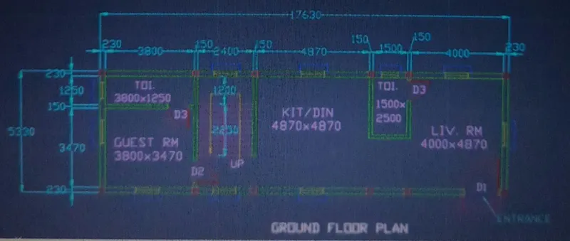
.Drop down the layer menu & select the walls layer.
.Type 'REC' in the command bow & press enter.
.Select dimension option in the dimension box.
.Specify length as 17630 & press enter.
.Specify width as 5330 & press enter.
.Type 'O' for offset in the command box.
.Specify 230 as offset distance & press enter.
.Select the last drawn rectangle & click inside the rectangle.
.Type 'EXPLODE' in the command box & press enter.
.Select the both rectangles & press enter.
.Type 'O' for offset in the command box.
.Specify offset distance distance as 3800 & press enter.
.Specify the left width of internal rectangle & click on right.
.Type 'O' for offset in the command box.
.Specify offset distance distance as 150 & press enter.
.Select the last offsetted line & press enter.
.Type 'O' for offset in the command box.
.Specify offset distance distance as 2400 & press enter.
.Select the last offsetted line & press enter.
.Type 'O' for offset in the command box.
.Specify offset distance distance as 150 & press enter.
.Select the last offsetted line & press enter.
.Type 'O' for offset in the command box.
.Specify offset distance distance as 4870 & press enter.
.Select the last offsetted line & press enter.
.Type 'O' for offset in the command box.
.Specify offset distance distance as 150 & press enter.
.Select the last offsetted line & press enter.
.Type 'O' for offset in the command box.
.Specify offset distance distance as 1500 & press enter.
.Select the last offsetted line & press enter.
.Type 'O' for offset in the command box.
.Specify offset distance distance as 150 & press enter.
.Select the last offsetted line & press enter.
.Type 'O' for offset in the command box.
.Specify offset distance as 1250 & press enter.
.Select the last offsetted line & press enter.
.Type 'O' for offset in the command box.
.Specify offset distance as 150 & press enter.
.Select the last offsetted line & press enter.
.Type 'O' for offset in the command box.
.Specify offset distance as 2500 & press enter.
.Select the last offsetted line & press enter.
.Type 'O' for offset in the command box.
.Specify offset distance as 150 & press enter.
.Select the last offsetted line & press enter.
.Type 'TR' in the command box & trim the extra portion.
Creating doors & windows in a ground floor plan:-
.Type 'TR' in the command box & press enter.
.Use trim command to make opening for the doors in different walls.
.For D1 make a 1500mm size opening in the walls.
.And 1000mm & 900mm size opening for doors D2,D3 respectively.
.For D1 drop down the layer menu & select the Doors layer.
.Type 'L' for the line command & press enter.
.Specify any start point.
.Specify the next point @25<180.
.Specify the next point @1500<90.
.Specify the next point @50<180.
.Specify the next point @1500<270.
.Specify the next point @50<0 & press enter.
.Click on 'ARC' option on ribbon & select start,end,direction, type arc to draw.
.Select the start point of Arc as end of the 1500 lenght line.
.Select the end point as the other end of the door opening.
.Give the suitable direction with suits the arc.
.Repeat the same procedure for D2 & D3 doors with their respective sizes.
. Select the whole door drawn & type 'CO' in the command box for copy & click on multiple.
.Pick the door & place it on desired as shown in plan.
.Use rotate command to rotate the object.
.For window drop down the layer menu & select the window layer.
.Create a vertical line of 230mm
.Type 'O' for offset in the command box.
.Specify offset distance as 1000 & press enter.
.Select the last vertical line & & click on right.
.Type 'L' for command line & press enter.
.Join midpoints of the last to drawn line & press enter.
.Select the whole window drawn & type 'CO' in the command box & for copy & click on multiple.
.Pick the windows & place it on desired places as shown in plan
.Repeat the same procedure for ventilator for its respective size.
.After drawing DOORS,WINDOWS,& VENTILATORS, convert each of them as block.
Creating staircase in ground floor plan:-
.Drop down the layer menu & select the 'STAIRCASE' layer.
.Type 'O' for offset in the command box & press enter.
.Specify offset distance as 1200 & press enter.
.Select the internal line segment of 2400 mm length wall & click at bottom.
.Now select the line & type 'CO' in the command box.
.Select Array option in command box.
.Specify no of item in array as 10.
.Specify the next item distance as '250' & press enter.
.Type 'TR' in the command box & trim the extra portion.
.For handrails make a line by connecting all centre point of the drawn steps.
.Type 'O' for offset in the command box & press enter.
.Specify offset distance as 50 & press enter.
.Select the last drawn line of 2250mm length & make offset of the line at both right & left side of the line.
.Type 'TR' in the command box & trim the extra portion & make the handrail as shown in figure.
.Draw the stairs in the entrance by the same process but with different dimensions.
Creating text in ground floor plan:-
.Drop down the layer menu & select the 'TEXTS' layer.
.Go to annotation tab & select the multitext command.
.Select the text style as 'ARIAL'.
.Specify the text height & scale.
.Specify the area where to put the text & type 'CO'& select multiple on the command box.
.Turn on 'ORTHO' & 'OSNAP' option off & put the copied text to the required places.
.Type 'ED' in the command box for 'EDITTEXT' command & press enter.
.Select the text & change the text as per requirement.
Creating dimension in ground floor plan:-
.Drop down the layer menu & select the 'DIMENSIONS' layer.
.Go to annotation tab & select the 'DIMLINEAR' command.
.Give all the linear dimensions.
.Use continue dimension command or baseline dimension command if required.
STEP3:-creating first floor plan:-
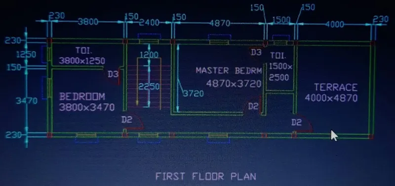
.Drop down the layer menu & select the walls layer.
.Type REC for rectangle command in command box & press enter.
.Select dimension option in the dimension box.
.Specify length as 17630 & press enter.
.Specify width as 5330 & press enter.
.Type 'O' for offset in the command box.
.Specify 230 as offset distance & press enter.
.Select the last drawn rectangle & click inside the rectangle.
.Type 'EXPLODE' in the command box & press enter.
.Select the both rectangles & press enter.
.Type 'O' for offset in the command box.
.Specify offset distance as 3800 & press enter.
.Specify the left width of internal rectangle & click on right.
.Type 'O' for offset in the command box.
.Specify offset distance as 150 & press enter.
.Select the last offsetted line & press enter.
.Type 'O' for offset in the command box.
.Specify offset distance as 2400 & press enter.
.Select the last offsetted line & press enter.
.Type 'O' for offset in the command box.
.Specify offset distance as 150 & press enter.
.Select the last offsetted line & press enter.
.Type 'O' for offset in the command box.
.Specify offset distance as 4870 & press enter.
.Select the last offsetted line & press enter.
.Type 'O' for offset in the command box.
.Specify offset distance as 150 & press enter.
.Select the last offsetted line & press enter.
.Type 'O' for offset in the command box.
.Specify offset distance as 1500 & press enter.
.Select the last offsetted line & press enter.
.Type 'O' for offset in the command box.
.Specify offset distance as 150 & press enter.
.Select the last offsetted line & press enter.
.Type 'O' for offset in the command box.
.Specify offset distance as 1250 & press enter.
.Select the last offsetted line & press enter.
.Type 'O' for offset in the command box.
.Specify offset distance as 150 & press enter.
.Select the last offsetted line & press enter.
.Type 'O' for offset in the command box.
.Specify offset distance as 2500 & press enter.
.Select the last offsetted line & press enter.
.Type 'O' for offset in the command box.
.Specify offset distance as 150 & press enter.
.Select the last offsetted line & click on bottom.
.Type 'TR' in the command box & trim the extra portion.
Creating doors & window in first floor plan:-
.Type 'TR' in the command box & press enter.
.Use trim command to make opening for the doors in different walls.
.Drop down the layer menu & select the 'DOORS' layer.
.The procedure of creating doors & windows is same as in the ground floor plan.
Creating staircase in first floor plan:-
.Drop down the layer menu & select the 'STAIRCASE' layer.
.Type 'O' for offset in the command box & press enter.
.Specify offset distance as 1200 & press enter.
.Select the internal line segment of 2400 mm length wall & click at bottom.
.Now select the line & type 'CO' in the command box.
.Select Array option in command box.
.Specify no of item in array as 10.
.Specify the next item distance as '250' & press enter.
.Type 'TR' in the command box & trim the extra portion.
.For handrails make a line by connecting all centre point of the drawn steps.
.Type 'O' for offset in the command box & press enter.
.Specify offset distance as 50 & press enter.
.Select the last drawn line of 2250mm length & make offset of the line at both right & left side of the line.
.Type 'TR' in the command box & trim the extra portion & make the handrail as shown in figure.
.Type 'TR' command in the command box & trim the extra portion & make the handrail as shown in figure.
Creating text in first floor plan:-
.Drop down the layer menu & select the 'TEXTS' layer.
.Go to annotation tab & select the multitext command.
.Select the text style as 'ARIAL'.
.Specify the text height & scale.
.Specify the area where to put the text & type 'CO'& select multiple on the command box.
.Turn on 'ORTHO' & 'OSNAP' option off & put the copied text to the required places.
.Type 'ED' in the command box for 'EDITTEXT' command & press enter.
.Select the text & change the text as per requirement.
Creating dimension in first floor plan:-
.Drop down the layer menu & select the 'DIMENSIONS' layer.
.Go to annotation tab & select the 'DIMLINEAR' command.
.Give all the linear dimensions.
.Use continue dimension command or baseline dimension command if required.
STEP4:-Creating 3D view:-
.Select ground floor plan view & type 'CO' command & copy view to a different location.
.Turn off layers 'off' except walls & 3d -wall-layers
.Drop down the layer menu & select the 3d-wall-layer.
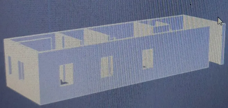
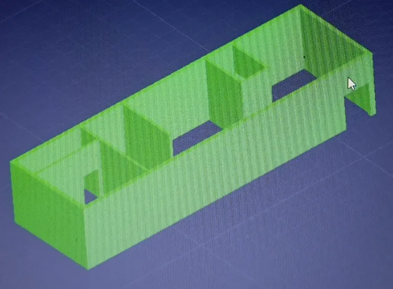
.Type'BO' in the command box & press enter.
.Select the inner portion of the plan walls & make boundary.
.Type 'EXTRUDE' & press enter.
.Select the last created boundary walls & press enter.
.Extrude the walls in Z-direction at a distance of 3600.
.Turn on 'DOOR' layer on & make boundaries at the place of doors & use the extrude command extrude the door boundary up to a height of 2000mm.
.Use the subtract command & subtract the door region from the wall region.
.The final result can be seen as follows:-
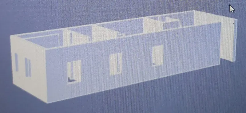
.Now turn the window layers on & create the boundary for the window as well.
.Use the extrude command & create the window of height 1500mm.
.Use the subtract command for subtracting the window from the 3d wall.
.The final result can be seen as follows:-
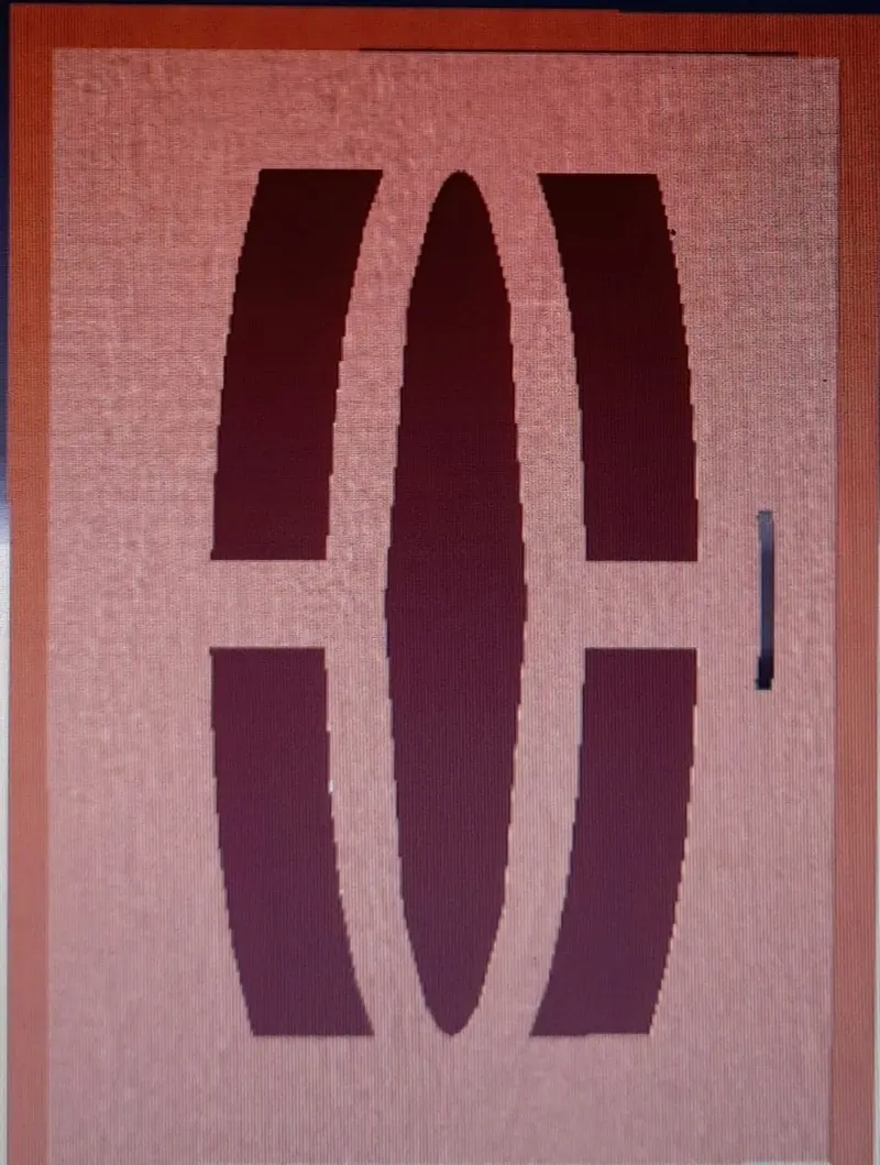
Creating 3D doors & window:-
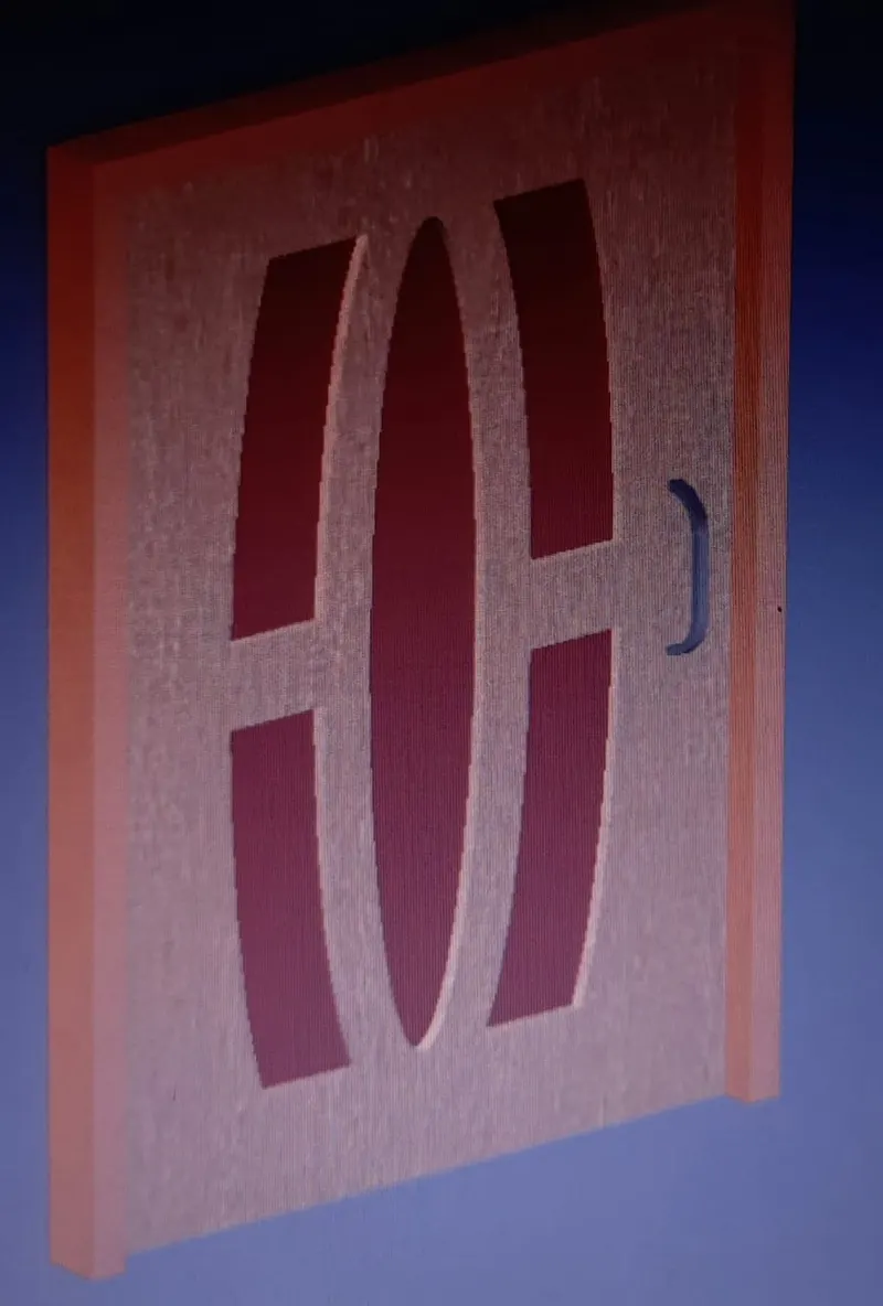
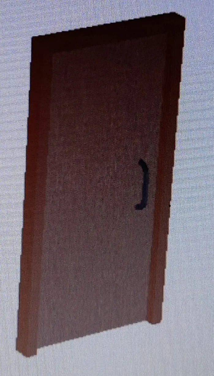
.Turn on the door layer & take a copy of doors D1,D2,D3 & paste at someother place in a drawing model.
.Take the plan view of the frame of the door & create a 3D path for the frame to go through by using polyline.
.Type 'SWEEP' command & press enter.
.Specify the frame of door as the object.
.Specify the polyline path for the sweep.
.After creating the frame , make the plan of door & use 'EXTRUDE' command to create the door.
.Repeat the same procedure for creating the remaining two doors D2,D3.
.Change the current layer to windows.
.Type 'UCS' & click on face & select the face having 150mm wide window.
.Type 'REC' command in the command prompt & press enter.
.Draw a rectangle of dimension @1000,1500.
.Specify the offset distance as 100mm.
.Specify offset object as rectangle & click inside the rectangle.
.Type 'O' in the command prompt & press enter.
.Specify offset distance as70mm.
.Specify offset object last offsetted rectangle & click inside the rectangle.
.Type 'BO' in the command box & click on points.
.Click inside the window frame area & press enter.
.Type 'SUBTRACT' in the command box & press enter.
.Select the bigger region & then select the smaller regions to subtract them.
.Follow the same procedure for all three boxes.
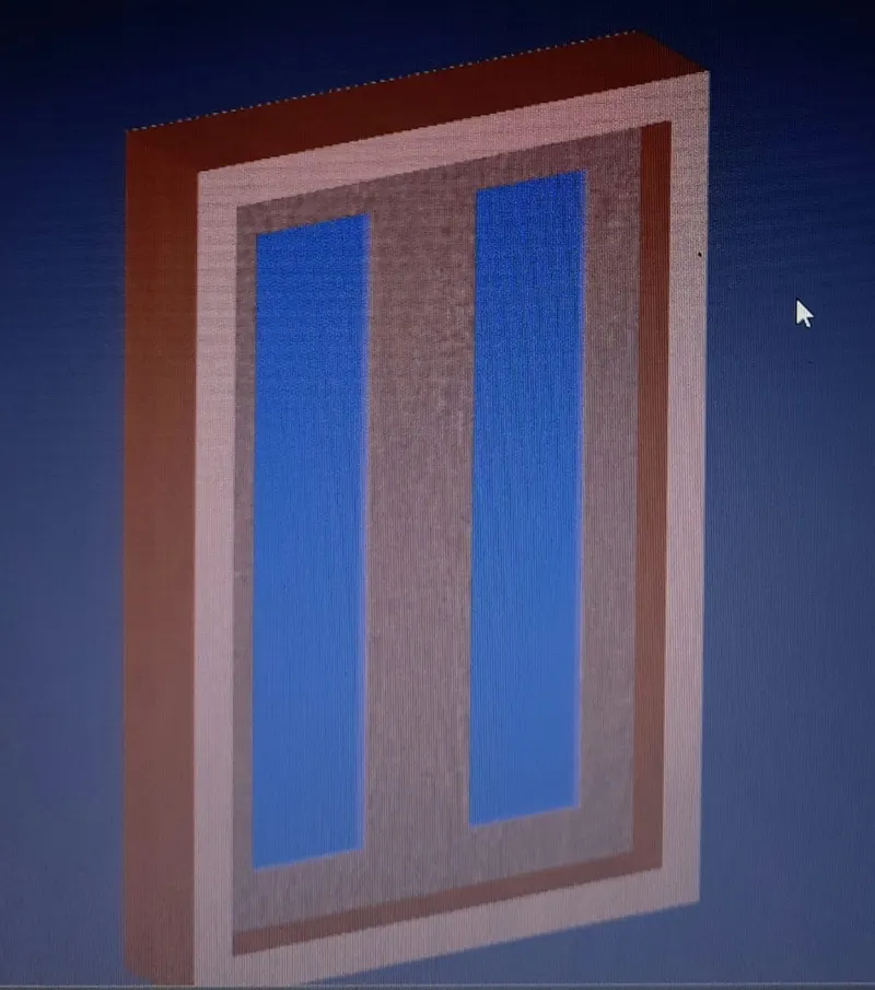
.Create the million area & glass area by the same procedure.
.
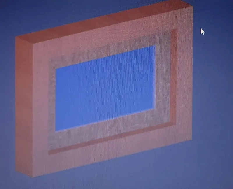
.Create the ventilation window size 700x500mm with the same process as the windows.
.
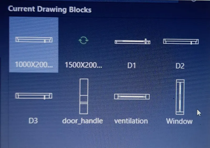
.After creating doors & windows concert them into the blocks with their respective names.
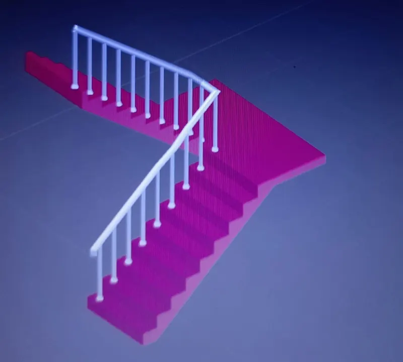
Creating 3D staircase:-
.Turn off all the layers except staircase.
.Change the view to 3d by clicking on home bottom of view cube & change the view to the right view.
.Set 'UCS ' at the right view.
.Type 'L' for line command.
.Draw a vertical line of length 200mm.
.Continue a draw a horizontal line of length 250mm.
.Repeat the same process for 10 times for dra 10 steps.
.After reaching the top step.
.Draw a landing of length 200.
.Press Esc to esc line command.
.Draw a line of 125mm at the bottom step.
.Draw a line of 125mm at the top right edge of landing.
.Draw a line of 125mm backwards.
.Draw a slab joining the lines.
.Change the view to 3d by clicking on home bottom of the view cube.
.Type 'UCS' in the command box & press enter type W & press enter.
.Set the view style control as 'REALSTIC'.
.Create a region from the side view of the stairs.
.Extrude the side view to a distance of 1200mm.
Type 3d mirror & press enter.
.SElect the staircase drawn & make the mirror reflection & place the created staircase by using 'MOVE' command.
.Use the object snap to place it in right place.
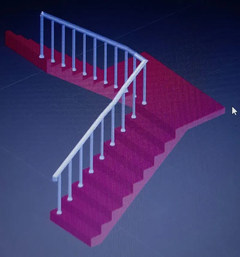
Creating handrails:-
.Change the current layer to Handrails.
.Draw circle of diameter 40mm with 50mm offset from the top right edges of the first thread of staircase.
.Change the circle into a region.
.Extrude the region to a height of 600mm as shown in the figure.
.Draw a handrail stand at the bottom with dimension 40mm & extrude.
.Change the current layer to handrail.
.Draw a polyline connecting all the top edges of handrails.
.Change the 'UCS' to front.
.Draw a circle of diameter 50mm on the top of the first handrail.
.Create a region of the circle drawn.
.Start 'SWEEP' command.
.Select the circle as object to sweep.
.Select the polyline drawn as path of sweep.
.Copy the same to the other side.
Creating floors:-
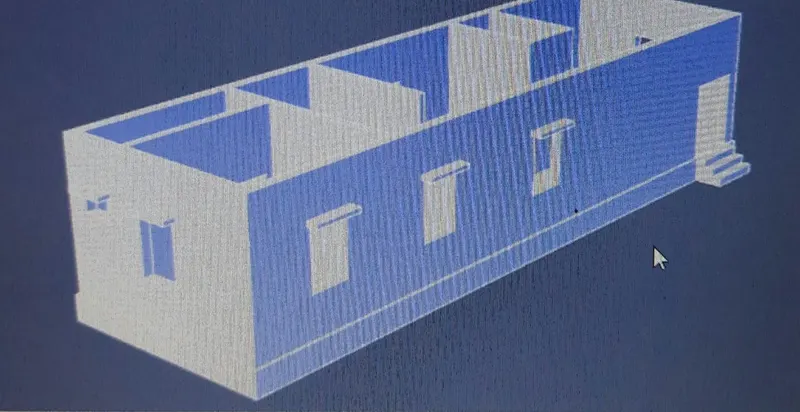
.Type 'REC' & press enter.
.Click on dimension & specify length as 17630 mm & width as 5330mm .
.Type 'O' & press enter.
.Specify offset distances 100mm & select the rectangle & make the offset outside.
.Type 'BO' & press enter.
.Make the boundary & press enter.
.Type 'EXTRUDE' & press enter now extrude the floor in 600mm in -ve Z axis to give a plinth depth.
.Type 'M' & press enter & move the created floor & place that below the ground floor 3d view created.
 .
.
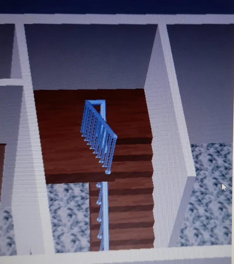
.Type 'M' & press enter.
.Specify the object as the 3d staircase created.
.Use the object snap & place the 3d stairs to the 3d ground floor plan.
STEP5:-Giving colour & materials to different objects:-
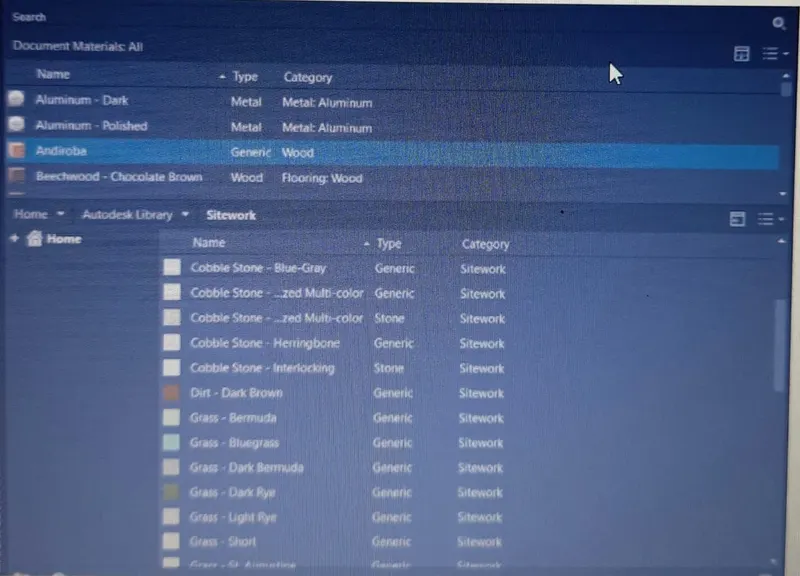
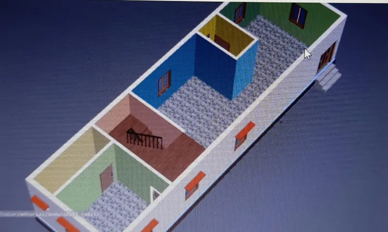
.Use the 'COLOUR FACES' tools in the 'SOLID EDITING' toolbar.
.Provide the colours to different interior walls of the floor.
.Use the 'MATERIAL BROWSER' tool in the 'visualize' tab & provide different materials to doors,windows,floors, staircase & plinth level.
STEP6:-Creating lights:-
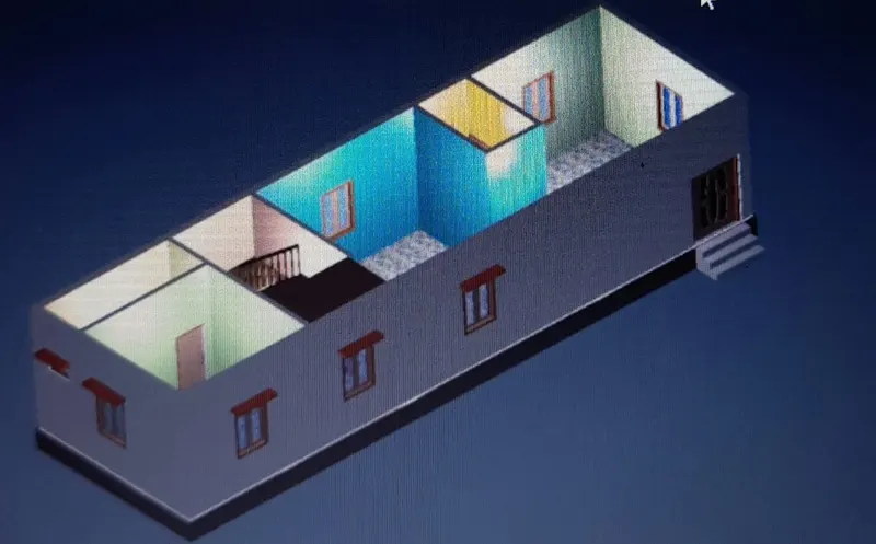
.Go to the 'VISUALIZE' tab & select the 'POINT LIGHT' tool
.Place the lights in different locations of the floor.
.Select all the lights & put them in the 'light' layer.
.Turn the light layer off.
Creating upper floor:-
.Repeat the same procedure as done in creating the ground floor.
.After creating the floor, use the move command to place the floor above the ground floor.
.
STEP7:-Creating 3D second floor:-
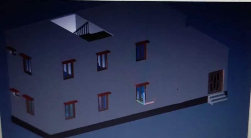
.Use the second-floor plan view.
.Create the boundary by using the 'BO' command.
.Use the extrude command to make the wall elevator of 3600mm.
.Use substance command to create the window precision in the wall.
.Use copy command to copy the staircase, windows & doors to put them in the 2nd floor.
.Create the floor for the roof by using same procedure as used for creating floors.
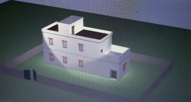
STEP8:-Creating mumty wall & outside boundary:-
.Take the plan view as a reference & create the mumty wall.
.Give material to the wall from material browser.
.Crete the outside wall of the house & create a gate opening for the main gate.
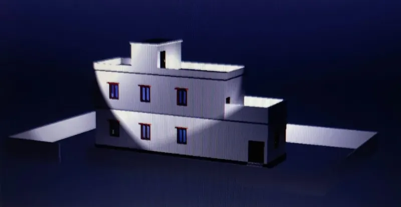
.Final prepared image of building:-
STEP9 Rendering:-
.After creating the 3d building & providing materials to it.
.Go to visualize tab.
.Set render quality to high.
.Start rendering.
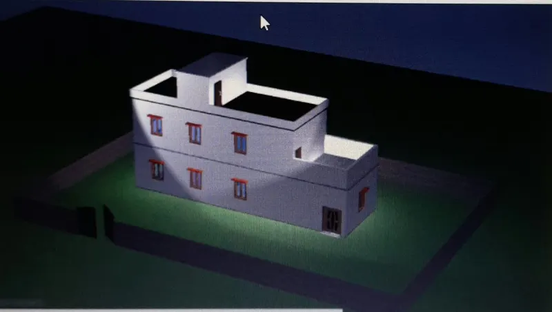
RESULT:-
Isometric view-
Staircase:-
DOORS:-
4)RENDERED VIEW1:-
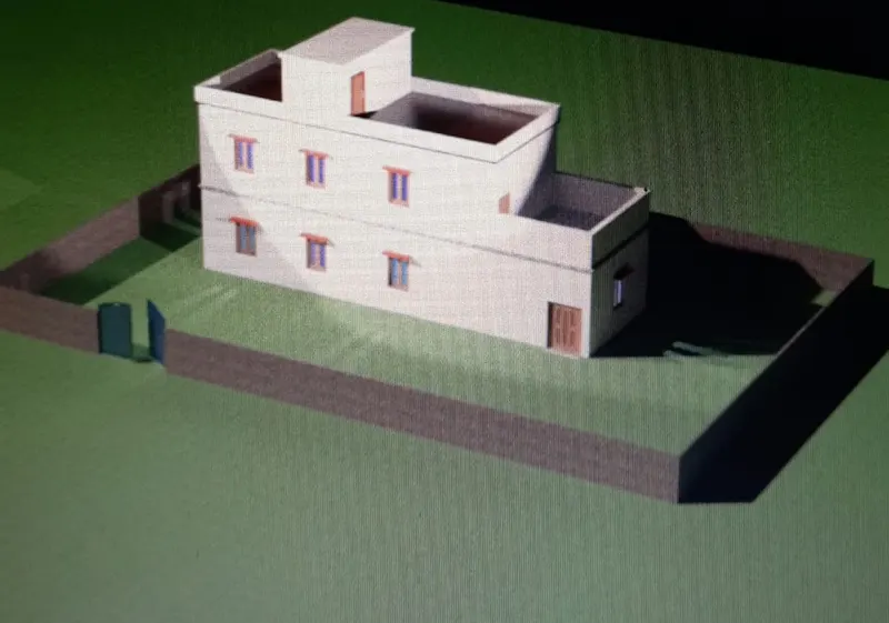
4)RENDERED VIEW2:-