Project 2_Creating a 3D rendered model for a Residential Building in AutoCad
RESIDENTIAL BUILDING WITH A RENDERED VIEW
AIM: Create a 3-dimensional model of the residential building with a rendered view.
INTRODUCTION:
Create a 3-dimensional model of the residential building with a rendered view. using layers, trim, extend, mirror, extrude,3dmirror, line, block, etc commands are used in the modeling.
PROCEDURE:
- created the plan using the line command and offset command of sizes 14' x 12' master bedroom, 13' X 20' and kitchen 10' X 10', 2 bedrooms on the first floor with 14' x 20', remaining place for steps and hall.
- by using creating layer command created the layer as walls, windows, doors, steps, furniture,extrusions, grass etc,
- by using the region command region created for the walls by selecting the lines, later that using the extrude command walls are created upto 10'6" from the bottom,
- later created layer at the bottom and extruded it upto -6" from the floor surface,
- select the UCS command and choose face place the cursor at the door frame wall,
- created the door by using the line and offset commands and added the materials using the material command, for door frames, and glasses.
- pasted the door into elevation, by using extrude command window outer is extruded, later that using subtract command window extruded from the wall to door.
- same as the doors windows are created by using the line and offset command and materials assigned as per requirement.
- by selecting UCS command on the face of the windows area by choosing face area, choose the windows copied them at required places,
- later that by using extrude command windows outer extruded,
- later by using subtract command windows are subtracted from the wall,
- create the rectangle at top of the wall by using the UCS at face top of the wall,
- choose the rectangle, extrude it by 6" thickness,
- after that select the ground floor plan total, copy it placed it on top of the ground floors walls,
- later that internal walls are created by using the line command,
- on top of the first floor created a rectangle and make extruded 6" and created the rectangle walls,
- make it region extended by using extrude command upto 5' height as a parapet wall,
- later choose the UCS place at the front view of elevation, creating the new look as seen in the image,
- later they added materials to that tools like glass, finishing, etc,
- finally check the elevations by using the 3DORBIT command,
- Measured the distance by using a dim command,
- later that created sunlight by choosing a light command, the light focus should be at the face of elevation,
- chose the render command, chose background ON, chose background as a plaza,
- the render quality placed at high, proceed for the render by placing render level5,
- click RR command for rendering, giving rendering create the rectangle large and extruded it by 2",
- assigned the material as grass to it,
- Click RR(Render) command, click enter save the image into JPG. rename it click on OK.
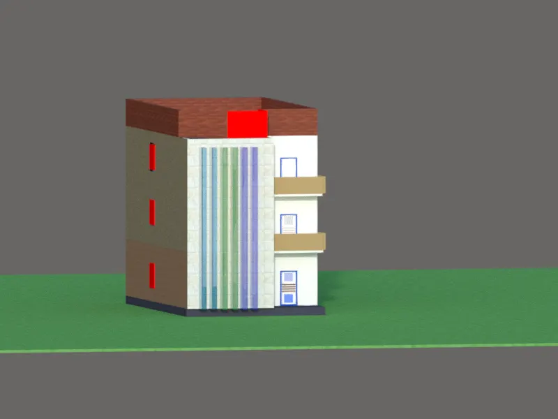
RESULT: Created a 3-dimensional model of the residential building with a rendered view.