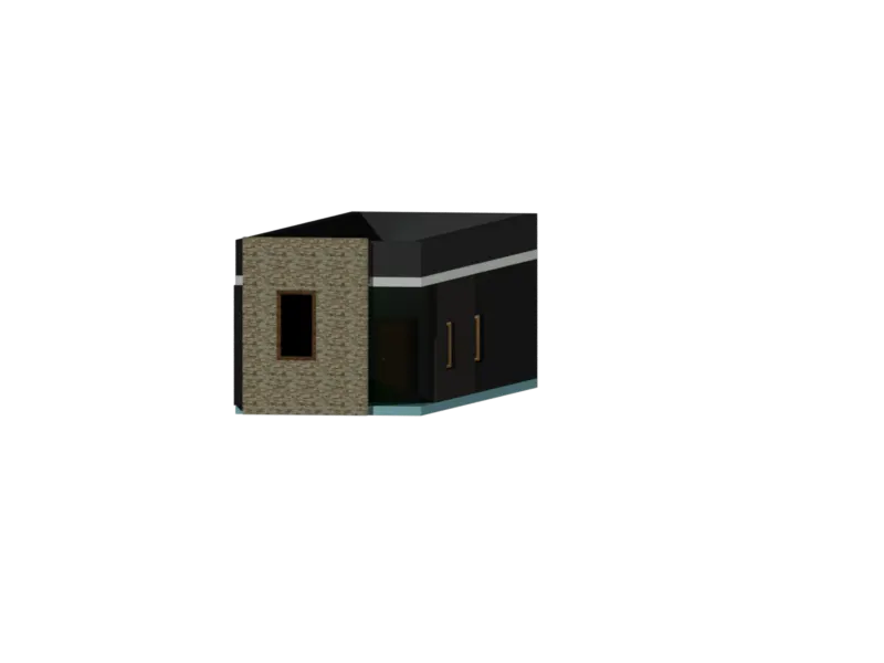
Project 2_Creating a 3D rendered model for a Residential Building in AutoCad
1. Aim: To create Create a 3 dimensional model of the residential building with a rendered view.
procedure: The following steps should be followed as a procedure to draw a given floor plan and To create Create a 3 dimensional model of the residential building with a rendered view using autocad
- To draw the given floor plan and To create Create a 3 dimensional model of the residential building with a rendered view. in autocad, the following steps should be followed as a procedure. At first open the AutoCAD and set dimensions that the dimensions are in feets and inches.
- Then enter the Line command in AutoCAD and after that enter the first point of the given diagram as that line should be started at the point in the coordinate system.
- Then with that point draw a rectangle using rectangle command using the dimensions of the rectangle as length is 60' and width is 20'.
- by using the offset command in autocad make offsset of 9" for the outer wall ie enter the dimension of the offset as 9".
- then select the last line of the rectangle and make offset of 4.5" ie the width of the both inner walls by using the offset command in autocad.
- next make offset of that line 4.5" ie the width of the inner wall is equal to 4.5", ie enter the offset command and give the width of 4.5".
- next make the offset of the line left corner of the rectangle to get the length of the bedrooms by using the offset command in autocad give the offset lenth as 9".
- Then with that point draw a rectangle using rectangle command using the dimensions of the rectangle as length is 9'9" and width is 13'.
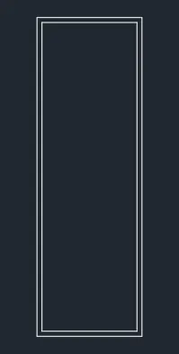
- next make offset of that line ie the width of the inner wall is equal to 4.5", ie enter the offset command and give the width of 4.5".
- next make the offset of the line left corner of the rectangle to get the length of the bedrooms by using the offset command in autocad give the offset lenth as 4.5".
- next make offset of that line 4.5" ie the width of the inner wall is equal to 4.5", ie enter the offset command and give the width of 4.5".
- next make the offset of the line left corner of the rectangle to get the length of the bedrooms by using the offset command in autocad give the offset lenth as 9".
- Then with that point draw a rectangle using rectangle command using the dimensions of the rectangle as length is 9'9" and width is 13'.
- by using the offset command in autocad make offsset of 9" for the outer wall ie enter the dimension of the offset as 9".
- then select the last line of the rectangle and make offset of 14'3" ie the width of the both bedrooms by using the offset command in autocad.
- next make the offset of the line left corner of the rectangle to get the length of the bedrooms by using the offset command in autocad give the offset lenth as 16'6".
- next make offset of that line 4' ie the width of the inner wall is equal to 150, ie enter the offset command and give the width of 13'.
- next make the offset of the line left corner of the rectangle to get the length of the bedrooms by using the offset command in autocad give the offset lenth as 4.5".
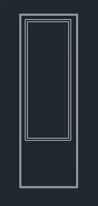
- by using the offset command in autocad make offsset of 9" for the outer wall ie enter the dimension of the offset as 9".
- then select the last line of the rectangle and make offset of 14'3" ie the width of the both bedrooms by using the offset command in autocad.
- next make the offset of the line left corner of the rectangle to get the length of the bedrooms by using the offset command in autocad give the offset lenth as 16'6".
- next make offset of that line 4' ie the width of the inner wall is equal to 150, ie enter the offset command and give the width of 13'.
- next make the offset of the line left corner of the rectangle to get the length of the bedrooms by using the offset command in autocad give the offset lenth as 4.5".
- next make offset of that line 14' ie the width of the inner wall is equal to 3050, ie enter the offset command and give the width of 4.5".
- by using the offset command in autocad make offsset of 9" for the outer wall ie enter the dimension of the offset as 9".
- make the offet of 14'6" and from that line make offset of 10'6" to get the width of the living room and the kitchen and make offset from that line of 4.5" for the inner wall and 9" as the outer wall as diameter.
- Trim the unwanted lines for the door and the other openings the length of the line of that doors as per the given dimensions.
- for stair case make the offset of the line left corner of the rectangle to get the length of the staircase 10" and raiser 7" by using the offset command in autocad give the offset lenth as 7".
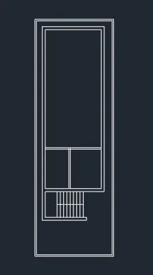
- next make offset of that line 14' ie the width of the inner wall is equal to 3050, ie enter the offset command and give the width of 4.5".
- by using the offset command in autocad make offsset of 9" for the outer wall ie enter the dimension of the offset as 9".
- make the offet of 14'6" and from that line make offset of 10'6" to get the width of the living room and the kitchen and make offset from that line of 4.5" for the inner wall and 9" as the outer wall as diameter.
- Trim the unwanted lines for the door and the other openings the length of the line of that doors as per the given dimensions.
- for stair case make the offset of the line left corner of the rectangle to get the length of the staircase 10" and raiser 7" by using the offset command in autocad give the offset lenth as 7".
- next make the offset of the line to get the length of the toilets by using the offset command in autocad give the offset lenth as 4.5" in both sides.
- next make the offset of the line left corner of the rectangle to get the length of the one of the bathrooms by using the offset command in autocad give the offset lenth as 12'6".
- next make the offset of the line right corner of the rectangle to get the length of the another bathroom by using the offset command in autocad give the offset lenth as 16'4".
- next make offset of that line 4.5" ie the width of the inner wall is equal to 300 ie enter the offset command and give the width of 4.5"
- delete the unwanted lines by using the trim command in autocad.
- next make the offset of the line right corner of the rectangle to get the length of the another bathroom by using the offset command in autocad give the offset lenth as 14"6".
- next make offset of that line 14"6" ie the width of the inner walls of lift is equal to 14'6", ie enter the offset command and give the width of 4.5"
- by using the offset command in autocad make offsset of 9" for the outer wall ie enter the dimension of the offset as 300.
- make the offet of 17'5" and from that line make offset of 17'5" to get the width of the living room and the another room and make offset from that line of 4.5" for the inner wall and 9" as the outer wall as diameter.
- Trim the unwanted lines for the door and the other openings the length of the line of that doors as per the given dimensions.
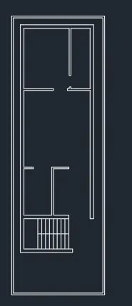
- next make the offset of the line to get the length of the toilets by using the offset command in autocad give the offset lenth as 4.5" in both sides.
- next make the offset of the line left corner of the rectangle to get the length of the one of the bathrooms by using the offset command in autocad give the offset lenth as 12'6".
- next make the offset of the line right corner of the rectangle to get the length of the another bathroom by using the offset command in autocad give the offset lenth as 16'4".
- next make offset of that line 4.5" ie the width of the inner wall is equal to 300 ie enter the offset command and give the width of 4.5"
- delete the unwanted lines by using the trim command in autocad.
- next make the offset of the line right corner of the rectangle to get the length of the another bathroom by using the offset command in autocad give the offset lenth as 14"6".
- next make offset of that line 14"6" ie the width of the inner walls of lift is equal to 14'6", ie enter the offset command and give the width of 4.5"
- by using the offset command in autocad make offsset of 9" for the outer wall ie enter the dimension of the offset as 300.
- make the offet of 17'5" and from that line make offset of 17'5" to get the width of the living room and the another room and make offset from that line of 4.5" for the inner wall and 9" as the outer wall as diameter.
- Trim the unwanted lines for the door and the other openings the length of the line of that doors as per the given dimensions.
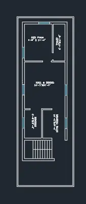
- and by using the multitext command or by copying the text which has been present in the another column the header text has been written sizes of the rooms or edited and edit the text as per the required and paste it on the row which has been present and edit the text and place the texting height as per the required table as shown in the figure below.
- edit the text as per the required and paste it on the row which has been present and edit the text and place the texting height as per the required table as shown in the figure below.
- to draw the door by using the autocad commands that by line command we can draw the line and by arc command we can draw the arc and by rectangle command we can draw the chouckets and then trim the unwanted lines. repeat the process for each and every door point side as per the required floor plan.
- enter the dimensions of the rooms as per the given dimensions using the Multi text command in autocad and enter the dimensions wich is required in the given floor plan to gte the required floor plan of the bathrooms and vanity and all other rooms.
- and by using the multitext command or by copying the text which has been present in the another column the header text has been written sizes of the rooms or edited and edit the text as per the required and paste it on the row which has been present and edit the text and place the texting height as per the required table as shown in the figure below.
- To draw the 3d model table in autocad, the following steps should be followed as a procedure. At first open the AutoCAD and set dimensions that the dimensions are in feets and inches.
- Then enter the Line command in AutoCAD and after that enter the first point of the given diagram as that line should be started at the point in the coordinate system.
- Then with that point draw a rectangle using rectangle command using the dimensions of the rectangle as length is 2'6" and width is 2'6".
- by using the offset command in autocad make offsset of 2' for the side of a table ie enter the dimension of the offset as 9'.
- then select the last line of the rectangle and make offset of 2.5' ie the width of the both side of a table by using the offset command in autocad.
- Open AutoCad Selecting Imperial system Command UN(units) and selecting Engineering with precision of 0’-0.0”. Command LIMITS and having limit of (0’,0’) in lower left corner and (100’,100’) in upper right corner. Command ZOOM and selecting All. Changing the Workspace from Drafting and annotation to the 3D modelling.
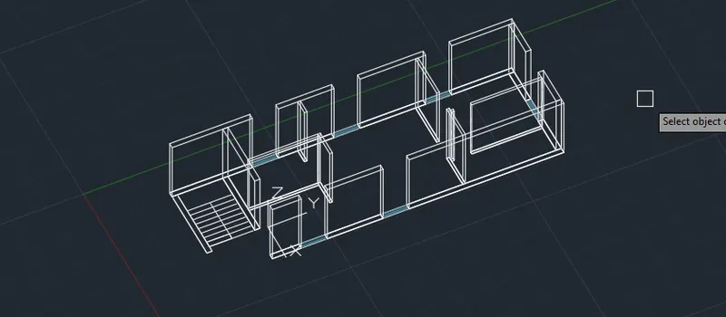
- To draw the 3d model table in autocad, the following steps should be followed as a procedure. At first open the AutoCAD and set dimensions that the dimensions are in feets and inches.
- Then enter the Line command in AutoCAD and after that enter the first point of the given diagram as that line should be started at the point in the coordinate system.
- Then with that point draw a rectangle using rectangle command using the dimensions of the rectangle as length is 2'6" and width is 2'6".
- by using the offset command in autocad make offsset of 2' for the side of a table ie enter the dimension of the offset as 9'.
- then select the last line of the rectangle and make offset of 2.5' ie the width of the both side of a table by using the offset command in autocad.
- Open AutoCad Selecting Imperial system Command UN(units) and selecting Engineering with precision of 0’-0.0”. Command LIMITS and having limit of (0’,0’) in lower left corner and (100’,100’) in upper right corner. Command ZOOM and selecting All. Changing the Workspace from Drafting and annotation to the 3D modelling.
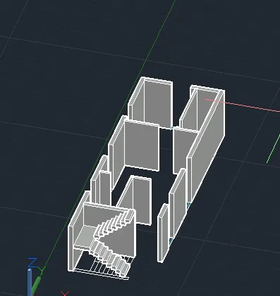
- To draw the 3d model table in autocad, the following steps should be followed as a procedure. At first open the AutoCAD and set dimensions that the dimensions are in feets and inches.
- Then enter the Line command in AutoCAD and after that enter the first point of the given diagram as that line should be started at the point in the coordinate system.
- Then with that point draw a rectangle using rectangle command using the dimensions of the rectangle as length is 2'6" and width is 2'6".
- by using the offset command in autocad make offsset of 2' for the side of a table ie enter the dimension of the offset as 9'.
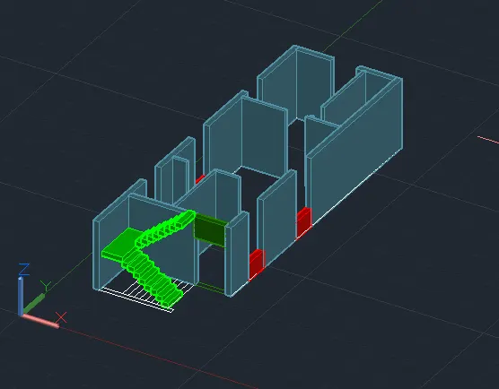
- set the Layer Properties Manager to manage your layers Find Create, rename, and remove layers Set the current layer on which new objects are automatically created Specify the default properties for objects on the layer Set whether the objects on a layer are displayed or turned off Control whether objects on a layer are plotted Set whether a layer is locked against editing Control the layer display properties for layout viewports Sort, filter, and group layer names
- A layer cannot be the current layer if The layer is frozen the layer is part of an external reference For certain types of objects, you can specify a default layer other than the current layer by setting a system variable. These include the following objects Dimension objects: DIMLAYER system variable Text and Mtext objects: TEXTLAYER system variable (added in the 2020.1 update) Hatch objects: HPLAYER system variable Centerline objects: CENTERLAYER system variable Center Mark objects: CENTERLAYER system variable Converted SHX text from imported PDF files: PDFSHXLAYER system variable
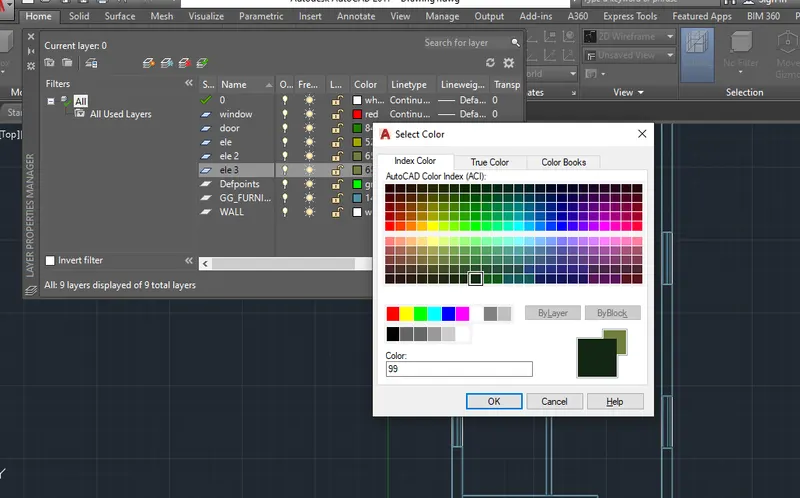
- Sometimes drawings can include dozens or even hundreds of layers. A layer filter limits the display of layer names in the Layer Properties Manager and in the Layer control on the ribbon. You can create layer property filters based on the name, color, and other properties. For example, you can define a property filter that lists all layers that include the letters "mech" in the layer name and are set to red.
- You can also create layer group filters where you choose specific layers to include in the group. For example, you could create a group called Tool Fixture that includes all the layers associated with the tool fixtures in your drawing. When you click the Tool Fixture group in the Layer Properties Manager, only the layers in the Tool Fixtures group are listed.
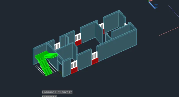
- hen enter the Line command in AutoCAD and after that enter the first point of the given diagram as that line should be started at the point in the coordinate system.
- Then with that point draw a rectangle using rectangle command using the dimensions of the rectangle as length is 2'6" and width is 2'6".
- by using the offset command in autocad make offsset of 2' for the side of a table ie enter the dimension of the offset as 9'.
- then select the last line of the rectangle and make offset of 2.5' ie the width of the both side of a table by using the offset command in autocad.
- Open AutoCad Selecting Imperial system Command UN(units) and selecting Engineering with precision of 0’-0.0”. Command LIMITS and having limit of (0’,0’) in lower left corner and (100’,100’) in upper right corner. Command ZOOM and selecting All. Changing the Workspace from Drafting and annotation to the 3D modelling.
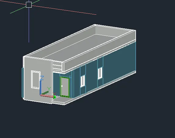
- Object surfaces: All object surfaces that have a surface hatch applied to them can also have a rendering material assigned. If you want to assign a rendering material to an object surface, make sure that the Surface Hatch component in the material definition is turned on.
- Live section views: The Sectioned Body component of a live section view as well as the live section cut plane can have special rendering materials assigned. If you want to assign rendering materials to a live section view, make sure that the Sectioned Body component in the material definition is turned on.
- Object surfaces: All object surfaces that have a surface hatch applied to them can also have a rendering material assigned. If you want to assign a rendering material to an object surface, make sure that the Surface Hatch component in the material definition is turned on.
- Live section views: The Sectioned Body component of a live section view as well as the live section cut plane can have special rendering materials assigned. If you want to assign rendering materials to a live section view, make sure that the Sectioned Body component in the material definition is turned on.
- select a material for Render Material. Then select a mapping type for Mapping If you select Same as Surface Hatch, only those surfaces selected under Surface Hatch Placement are rendered. If you select Face Mapping, all surfaces are rendered and any hatch alignment overrides are ignored.
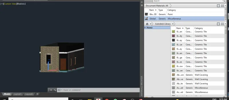
- rendered image can be created for a new model without attaching materials, placing user-defined lights, and adding a background. By default, a default material is added to all 3D objects in a model and the renderer automatically uses two default distant lights when user-defined lights are not placed in a scene. As an alternative to the two default distant lights, you can specify the use a single default distant light that shines from over-the-shoulder. Default lights cannot be moved or adjusted.
- A realistic rendering of a 3D model can often give a product team or prospective client a clearer vision of a conceptual design than a plotted drawing.
- Rendering is the process of creating a raster image based on the 3D objects in a scene. A renderer is used to calculate the appearance of the materials attached to the objects in a scene, and how lighting and shadows are calculated based on the lights placed in a scene. Environmental and exposure settings of the renderer can be adjusted to control the final rendered image.
- A realistic rendering of a 3D model can often give a product team or prospective client a clearer vision of a conceptual design than a plotted drawing.
- Rendering is the process of creating a raster image based on the 3D objects in a scene. A renderer is used to calculate the appearance of the materials attached to the objects in a scene, and how lighting and shadows are calculated based on the lights placed in a scene. Environmental and exposure settings of the renderer can be adjusted to control the final rendered image.
- rendered image can be created for a new model without attaching materials, placing user-defined lights, and adding a background. By default, a default material is added to all 3D objects in a model and the renderer automatically uses two default distant lights when user-defined lights are not placed in a scene. As an alternative to the two default distant lights, you can specify the use a single default distant light that shines from over-the-shoulder. Default lights cannot be moved or adjusted.