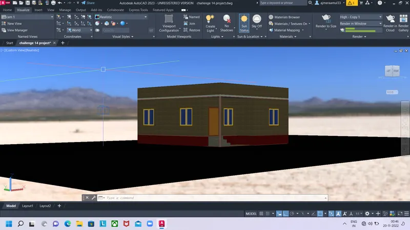
Project 2_Creating a 3D rendered model for a Residential Building in AutoCad
Aim: Creating a 3D model of the residential building with a rendered view.
Introduction: 3D modelling is very intresting. That we can convert 2D view into 3D view of any drawing. Such tools are very intresting to use. As we can convert any drawing into 3D view.
After 3D modelling the rendering is done. It shows the drawing into such intresting view. Rendering is done in low,medium and high. We can create different views of object into rendering.
We can print the rendering view and saved as file.
Procedure
Type UN in the command line
Select units as engineering or decimal
Select the precisions
Type LIMITS in the command line
Set lower limit and upper limit
Press Z enter and A enter to fit the screen
Select the top view of the drawing
And visuals style as 2D wireframe
Now draw the plan of the building with assumed dimensions
Assume all dimensions
After drawing the plan of a building now draw a front elevation of the building
Use such tools like LINE,XLINE,TRIM,FILLET,OFFSET
Write the texts to specify the rooms of the building
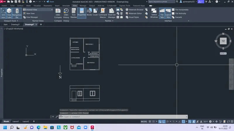
Now select the default view of the 3D modelling
Create different layers like 3D wall,3D window,3D frame,3D glass,3D floor,3D plinth ect., and specify the suitable colours to those layers
Copy the plan of the building
Make regions by Boundary command and select the regions
Now by using the EXTRUDE tool extrude the regions
The walls of the building is extruded in the 3D wall layer
The window space is created for windows
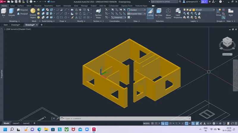
Now create a rectangle at the bottom of the extruded walls
So we can extrude create a plinth level of the building
And now creating the column outside of the building
Steps are created in front of the door
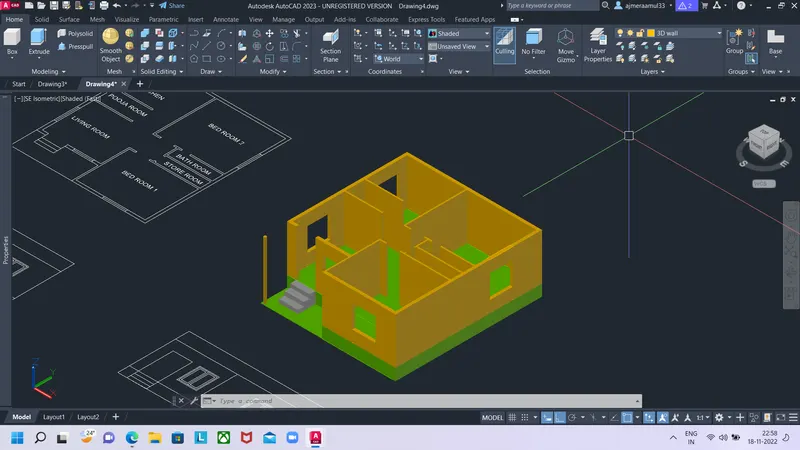
Now rotate the 2D plan of the building at 90 degrees by using rotate3D tool
Move the elevation to the extruded walls
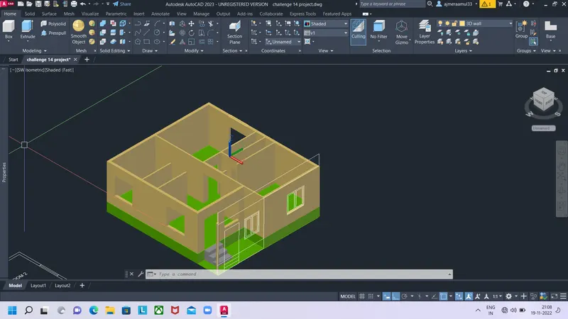
Now create the window frames
And window mullions
Window glass
The windows created as per the size required for the building
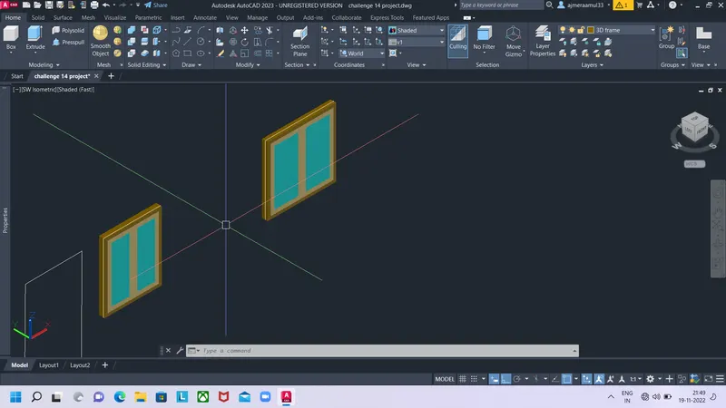
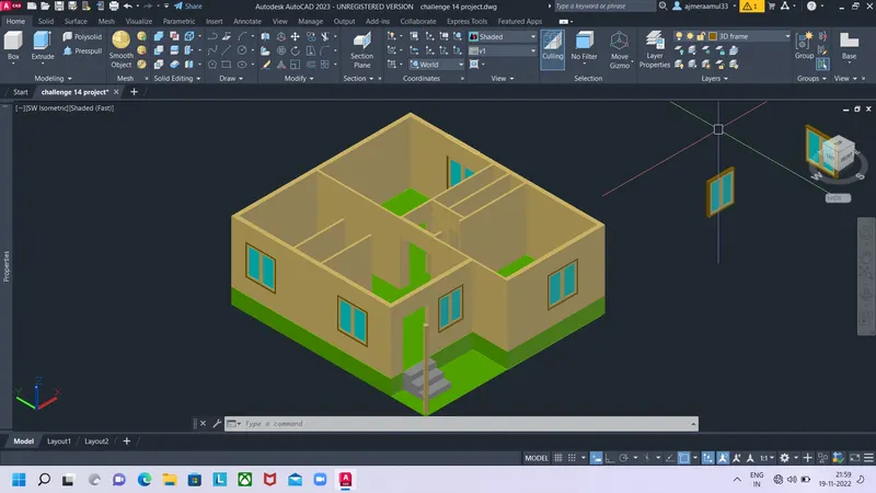
After creating the windows copy the window and paste where they required
After pasting the it looks like
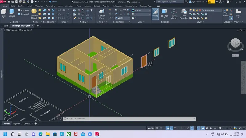
Now create a door frame in required dimensions
Select the colours to the frame and door panel
Copy and paste the door where it required
Now create the slab for building
Create parapet wall
Create a camera and save the views of the drawing
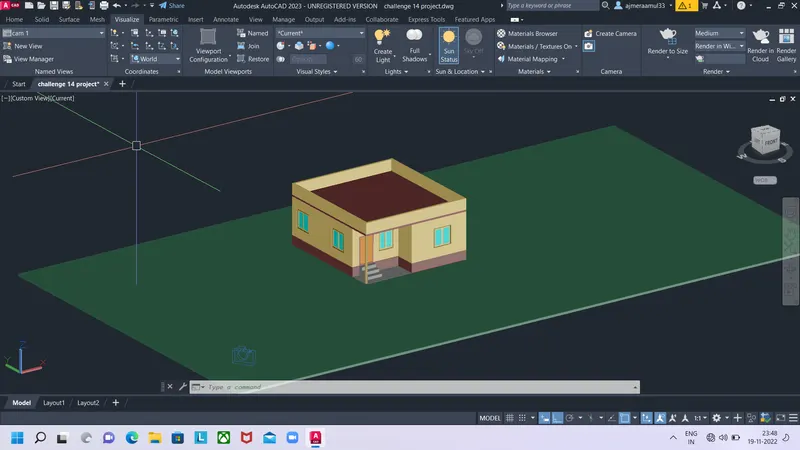
Now type MAT in command line
Select the suitable paints,suitable stone designs required for drawing
Apply the suitable designs to the drawing
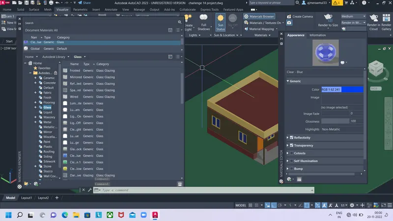
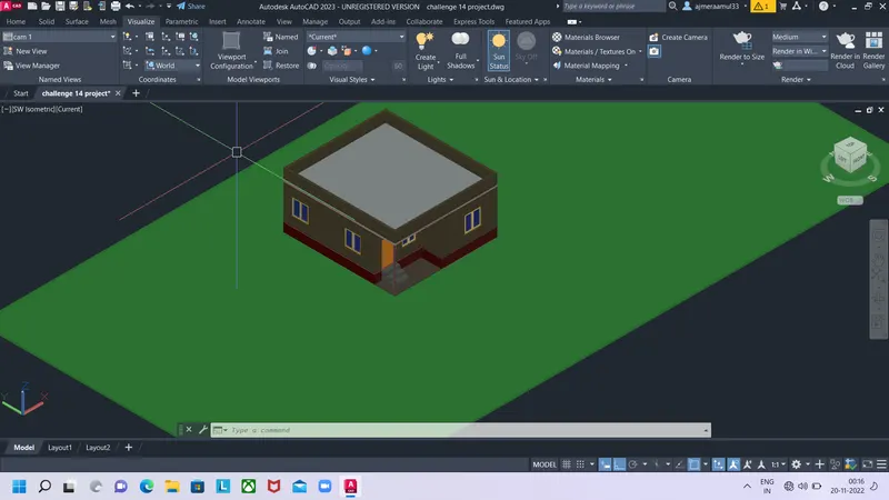
Now go to command RR and create a rendering of the drawing in different views
Select the redering size of the drawing
Go to render option select the environment as we like
Now the 3D modelling of the residential building is created
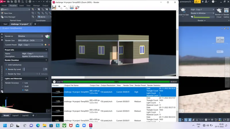
Result:
After rendering the drawing we get below drawing