Project 2_Creating a 3D rendered model for a Residential Building in AutoCad
Create a 3 dimensional model of the residential building with a rendered view.
AIM:
To create a three-dimensional model of the residential building with a rendered view using AutoCAD.
INTRODUCTION:
3D MODELING
- AutoCAD is a three-dimensional CAD software that is used widely for all tpye of projects
- AutoCAD offers an exclusive range of commands and functions both for 3D as well as 2D modeling and drawing with an various set of tools
- 3D is all about the third coordinates which is Z axis, While using 2D we only cares about X and Y axis and most of the times coordinates are used
- Whereas,while working with 3D the user uses all the coordinates which makes the work even more easier
- Three dimensional CAD is used for drafting our project relevsnt to the reality
- It is the process of creating a mathematical representation of any surface using a various tools
- An architectural 3D model is much more intresting and realistic then 2D model
- In 3D design, the user gets to know the physical dimensions of the objects and their distance in relation to other objects in the total layout. This feature helps enormously to see and modify arrangements of object based on their sizes.
3D RENDERING
- In 3-D graphic design, rendering is the process of add shading, color, and lamination to a 3-D wireframe drawings and converting them into a realistic view is known as rendering.
- A rendering is useful for the client to see how the decisions made with the architect will look in three-dimensional manner, So they can visualize how the certain finishings suites to the reality of a building.
- 3-D rendering is a form of virtual photography.
- The 3D printing is faster when using CAD designes rather than traditional 2D drawings, 3D rendering image can be used in variety of purpose.
- A realistic rendering of a 3D model can often give a product team or prospective client a clear vision of a conceptual design than a plotted drawing.
- Rendering is used to calculate the appearence of the materials attached to the objects, and how lightings and shadows are calculated based on lights placed in the scene
- Environmental and exposure settings of the rendered can be adjusted to control the final rendered image.
3D COMMANDS USED:
- UCS
- Extrude (EXT)
- Layers
- Box
- Union (UNI)
- Substract (SU)
- Presspull (PRESS)
- Intersection
- 3DMove (3DMo)
- 3DRotate (3DRo)
- 3d orbit (3DO)
- Polyline (PL)
- Trim (TR)
- Join (J)
- Copy (CO)
- Loft
- Polyline (3DPOLY)
- Sweep
- Rectangle (REC)
- Boundary (BO)
- Blocks (B)
- Region (REG)
- Material browser (RMAT)
- Material mapping (SETUV)
UCS:
- The user coordinate system (UCS) establishes the location and orientation of movable cartesian coordinate system, it is essential tool for many precision operations.
- All objects in drawing are defined by their coordinated in the world coordinates system(wcs), a permanently fixed cartesian coordinate system.
- To define your UCS manually, click two points to define the orientation of the X axis. To set your ucs based on the angle of an object in your drawing, such as polyline click that object as you move your cursor up or down a 90 degree line will extending from the object you selected
- The ucs icon changes automatically depending upon current visual style, The colorful 3D icon on the right displays when a 3D visual style is current.
- The UCS icon follows the traditional right-hand thumb rule in determining positive axis directions and rotation directions.
MATERIAL BROWSER (RMAT):
- The material browser allows you to navigate and manage materials provided by autodesk libraries.
- Once all the objects are drawn then final step is to deciding which material we going to use for each objects, material browser give you various types of material available in autodesk library.
- The material to be assigned to all the objects so that while rendering it will give a clear vision of drawings
- While assigning the material keep the visual style to realistic so that it is only visible in realistic style only.
- To get material browser go to visualize > material browser, or command - RMAT.
EXTRUDE:
- The extrude command will extrude a 2D object into a 3D object
- It creates a 3D solid form an object that encloses an area, or a 3D surface from an object with open ends. Objects can be extruded orthogonally from the plan of the source 2D object in a specified direction, or along a selected path
- When using extrude command the original 2D object will be removed from the drawing
BOX:
- The BOX command will allow you to create a 3D box by selecting 3 points i,e length, width and height
PRESSPULL:
- The presspull command will extrude a 2D object into a 3D object, or extend a 3D surface
- When using the presspull command with a 2D object, the 2D object will remainin the drawing
UNION:
- The UNION command allows you to join the 2 or more objects into a singkle objects
- Modify > solid editing > union
SUBTRACT:
- This command is used to remove the objects present together
- If two objectws are placed one above the another and if we want to remove one of them then we go with command SUB select the source object press enter then select the object that you want to remove
- And a single new 3D solid object is created
3DMOVE:
- The 3Dmove command allows you to move the objects in either X, Y or in Z-axis
- Select the objects and subobject you want to move using the following methods - press and hold ctrl to select subobjects face, edges and vertices and release ctrl to select whole object
3D ORBIT:
- Command 3DO to get 3D orbit cursor by this you can rotate the objects in all directions and see all sides with fixed axis
- You can go with command or press shift + the whwwl of the mouse and then move the mouse you will jump into 3D orbit
BOUNDARY:
- It creates a region or a polyline from enclosed areas
- Command BO options are displayed, the interior point that you specify uses the surrounding and interior objects to create closed polyline and region.
- Hometab > draw panel > click boundary or command boundary
REGION:
- It converts objects that encloses an area into 2d region object, it basically a closed boundary that these objects that we've got in drawing are changes to a region
PROCEDURE:
1. Setting the drawing parameters:
- Open the AutoCAD and create new drawing page by using command - "STARTUP" which starts from scratch and enter new value for the startup and open the new drawing file as imperial system (feet and inches).
- In command prompt type - "UNITS" a units dialog box appears set the units - Engineering and precision - 0'0''
- Then to set the upper and lower limits command box type - "LIMITS" and give the lower limits as - 0',0' and upper limits as - 500',500'
- Once all the parameters are fixed to drawing then type - "Zoom" in commands and give zoom all.
- Then go to Status bar > workspace current > 3D modeling or command WSC and type 3D modeling to change the working space from 2D to 3D space.
- And in navigation bar click on the view cube to on.
- B. Creating layers:
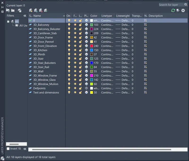
- Create the layers which you going to draw name all the objects and assign different color for each elements
- To create layer go to ribbon > Home tab > layer properties > create new layer , or in command prompt type - "LA" > right click > create new.
- The layers which used to create entired drawings are listed below,
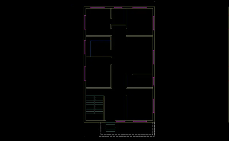
2. Drawing Plan:
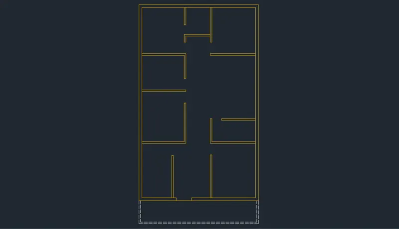
- Plot area - 57'3'' x 31'
- Outer wall thickness - 9''
- Inner wall thickness - 5''
- Keep the view on top , UCS to world and visual style as - 2D wireframe.
- In command prompt type - "LA" and set the 3D_Wall layer as current layer.
- And create a rectangle by using - "REC" command, of dimensions 31'(width) and 57'3'' (length)
- Then command - "O" and offset the created rectangle to 9'' inner side to make a outer wall thickness.
- Type "EXPLODE" in command box and explode the inner rectangle, offset the inner rectangle towards east side for 11' , 7' , 11'-4'' along with the wall thickness of 5'' for each offset values respectively.
- Similarly by using command - "O" the following offset values are made on top line towards south side for 11' 3 times and 9'-7'' , 5'-6'' along with 5'' inner wall thickness respectively.
- For right hand side rooms offset the bottom rectangle line towards north side for a distance of 11'4'' , 11'4'' , 16'6'', 11'4'' along with 5'' inner wall thickness for each offset.
3. Creating Doors, Windows, Staircase:
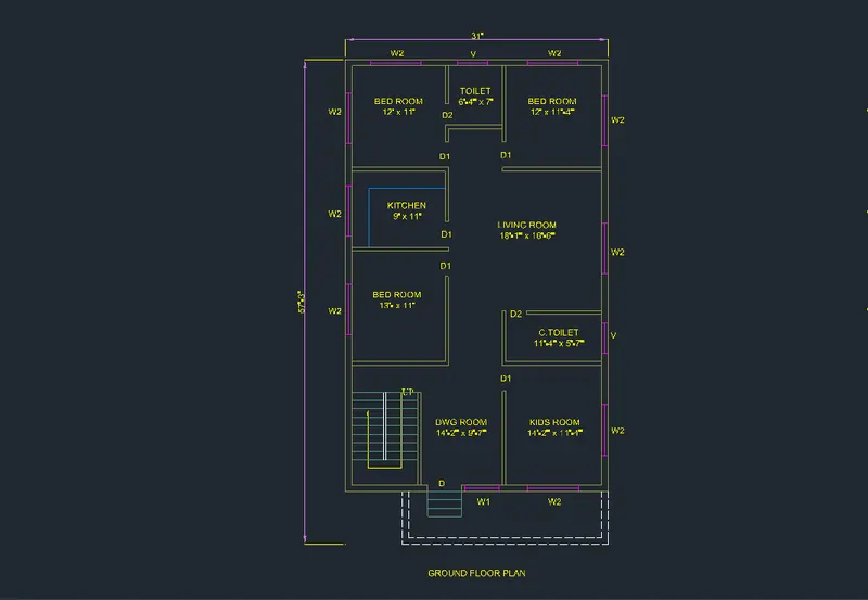
The standard doors and windows size used in this drawings are listed below in table form,
Door name Door size
D1 3' x 7'
D2 2'-6'' x 7'
D 4' x 7'
Window name Window size
W1 4' x 4'
W2 6' x 4'
V 2'-3'' x 2'-6"
Stair name Stair size
Thread 1'
Rise 6''
- The doors are created as per the standard size and place wherever required,
- Similarly the windows are created accordilgly to standard size and placed with making window layer as current layer
- For staircase set the layer corresponding to stair as current layer and draw stair using line command
4. Dimensioning and Texting:
- To create a text and dimension we need to set the dimension styles
- In command prompt type - "DIMSTYLE" and create the new dimension style as - "Times new1" and assign the arrow head height and line color.
- Then create a new font style as - "Times roman" > set font style to times new roman > set height to 9'' > set current.
- Then go to layer properties and set the dimension and text layer to current and create the text wherever required.
- The ground floor plan is made
5. G+1 Storey Plan:
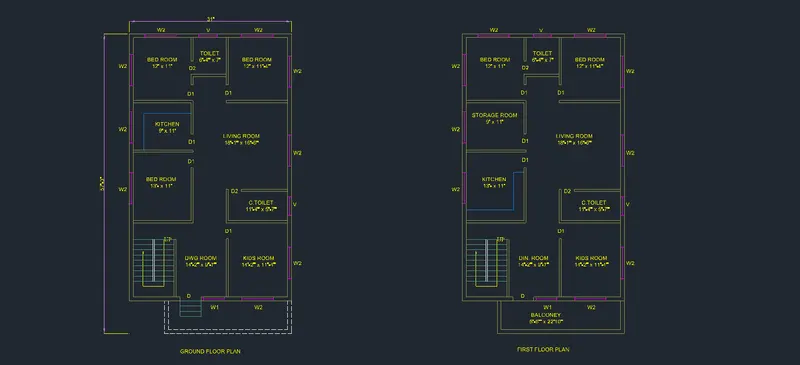
- By using the command - "Co" copy the ground floor plan and place on its side.
- The First floor plan has few changes Balconey comes over which dimensions about 5'-10'' x 22'-10'' and storage room are also placed but not as major changes done
- The ground floor and first floor plan are shown below,
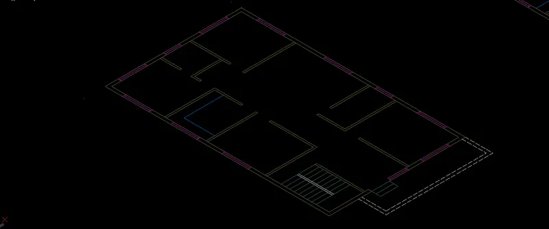
- Copy the ground floor plan aside and change the viewcube to side view
- Remove the dimensions and texts only plan is placed
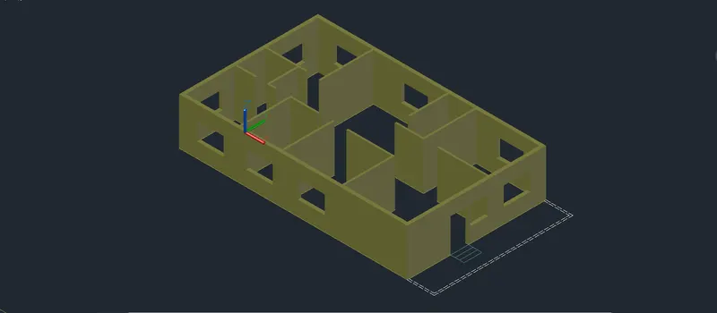
6. Creating 3D_Wall:
- In command prompt type - "REG" and create a region of all the walls.
- By using - "EXT" command extrude the wall to a total height of 10'6'' from the plinth level up to sill level
- After extruding all walls create a rectangle over the window keeping wall layer current and extrude to 3'4'' as well.
- Then place the ucs over the top wall by using command - "UCS" > face
- Create a rectangle connecting two window walls on all the sides
- In command prompt type - "REG" and create a region of all the created rectangle then,
- By using "EXT" command extrude the top region to -z axis for height of -3'2'' towards bottom
7. Creating 3D_Window:
Creating W1
- Command - ucs and place the ucs on the front view by using face option.
- Go to layer properties and set the 3D_Window_Frame layer current and in command box type - "REC" and create a rectangle of size about 4' x 4'
- Then using command " O" offset the rectangle to 3'' inside to create a window frame.
- Then command "REG" create a region on window frame and by using "SU" command subtract the inner region from the outer region.
- In similar way create a rectangle by keeping 3D_Window_Mulion as current layer and make them as region by using "REG" command and subtract the inner mulion from outer,
- Again create a rectangle by keeping 3D_Window_Glass as current layer and make them as region.
- Once all the frame, mulion, glass are set to regioned then extrude the frame, mulion and glass to -5", -3" , -3" respectively
- In command prompt type - "M" move the mullion and glass to 2'' inner side
Creating W2
- Command - ucs and place the ucs on the front view by using face option.
- Go to layer properties and set the 3D_Window_Frame layer current and in command box type - "REC" and create a rectangle of size about 6' x 4'
- Then using command " O" offset the rectangle to 3'' inside to create a window frame.
- Then command "REG" create a region on window frame and by using "SU" command subtract the inner region from the outer region.
- In similar way create a rectangle by keeping 3D_Window_Mulion as current layer and offset to 4'' then make them as region by using "REG" command and subtract the inner mulion from outer,
- Again create a rectangle by keeping 3D_Window_Glass as current layer and make them as region.By using line command "L" draw a line from center of the mulion offset the created line 3'' on each side to make a glass frame.
- Once all the frame, mulion, glass are set to regioned then extrude the frame, mulion and glass to -5", -3" , -3" respectively.
- In command prompt type - "M" move the mullion and glass to 2'' inner side.
- Creating Ventilation:
- Go to layer properties set the 3D_Window_Frame to current layer and create a rectangle of dimensions 2'3'' and 2'6''. And offset the rectangle to 2'' innerside to make window frame.
- Set the 3D_Window_Mulion current and create a rectangle, make tem region and by using "EXT" command extrude the 3D_frame and 3D_Mulion to -5'' and -3''
- Set the 3D_Window_Glass to current and create a rectangle to make glass and make it as region by using "REG" command then extrude it.
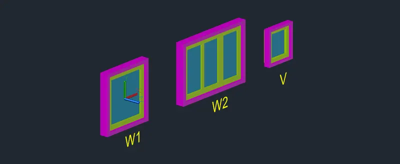
- Then Create a block of all windows so that it can be easily inserted wherever required and exploded
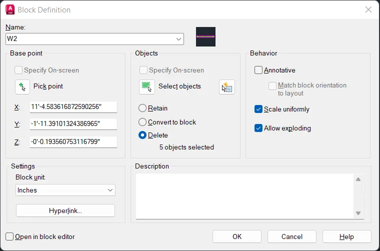
- To create a block command- "B" a block definition dialog box appear give name as W1, W2 and V
- Pick the base pont and select the whole objects and click on allow exploding
- Delete the box when window block is created
8. Creating staircase:
- In command prompt type - "UCS" set the ucs to side view by clicking face option and place it on the side.
- Go to layer properties set the 3D_Stair layer to current
- Start line command and draw a vertical line of length 6”
- Draw a horizontal line of length 1’ the threader and riser are created
- Repeat the same process for 9 times to draw 9 steps
- After reaching 9 steps draw a landing of length of 2’
- Draw a line of 1-6''’ at the bottom step
- Draw a line of 6” at the top right edge of landing
- Draw a line of 1’6” backwards
- Draw a slab joining the lines
- Change the view to 3d by clicking on home button of view cube
- Set UCS as world
- Set the view style control as REALISTIC
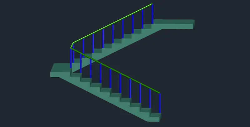
- Create a region from the side view of the stairs
- Extrude the side view to a distacne of 3’ as shown in figure
- To create hand railings,
- Change the current layer to Stair_Handrails
- Draw circle of diameter 1” with 2” offset from the top right edges of the first thread of staircase
- Change the circle into a region
- Extrude the region to a height of 3’ as shown in the figure
- Change the current layer to Stair_handrails_Stand
- Draw a handrail stand at the bottom with dimension 2” and extrude as shown in figure
- Using copy command copy all the hand rail components on all stairs with same offset as shown in figure.
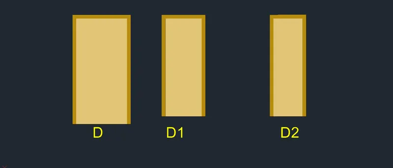
9. Creating Doors:
Creating Door D:
- Place the ucs on front side by using command ucs > face
- Go to layer properties set the 3D_Door_Frame to current, create a rectangle of size 4' x 7' and offset the rectangle to 3'' inner side, then trim the bottom and and extend the inner line to bottom.
- Command "REG" and make a region of frame then set the 3D_Door_Panel as current layer, create a rectangle over a inner frame rectangle, then make it as region
- By using the command "EXT" extrude the region to 5'' on -z axis
Creating Door1:
- Place the ucs on front side by using command ucs > face
- Go to layer properties set the 3D_Door_Frame to current, create a rectangle of size 3' x 7' and offset the rectangle to 3'' inner side, then trim the bottom and and extend the inner line to bottom.
- Command "REG" and make a region of frame then set the 3D_Door_Panel as current layer, create a rectangle over a inner frame rectangle, then make it as region
- By using the command "EXT" extrude the region to 5'' on -z axis
- Creating Door2:
- Place the ucs on front side by using command ucs > face
- Go to layer properties set the 3D_Door_Frame to current, create a rectangle of size 2'-6'' x 7' and offset the rectangle to 3'' inner side, then trim the bottom and and extend the inner line to bottom.
- Command "REG" and make a region of frame then set the 3D_Door_Panel as current layer, create a rectangle over a inner frame rectangle, then make it as region
- By using the command "EXT" extrude the region to 5'' on -z axis
10. Placing Doors, Windows, Stairs:
- Command- Ucs and place the on front face place then windows and doors
- Place the created windows over the window openings, By using "I" insert command insert the windows wherever required
- Then place a door frame in the openings by inserting the doors, similiarly place the staircase as well.
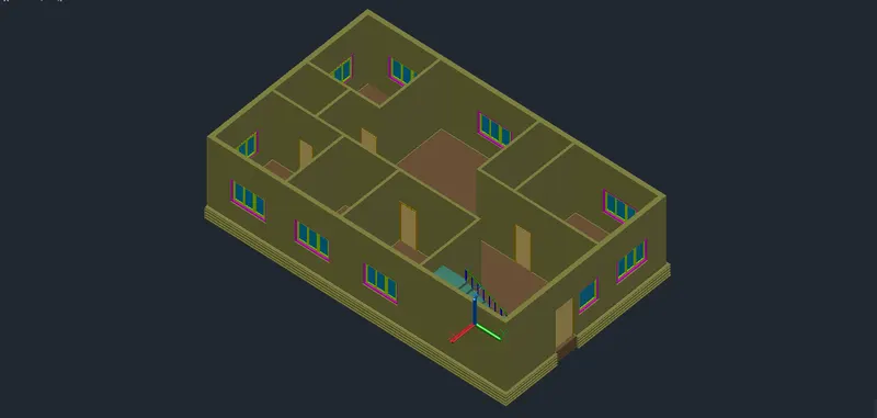
- Go to layer properties set the 3D_Floor as current
- Command - "UCS" and place the ucs over the top of the 3D_Wall, then create a rectangle connecting inner side of wall.
- Make it as region by using "REG" in command box then extrude the region to a height of 6'' in z axis which is a floor thickness
- Then by using command "CO" copy the ground floor to the top creating the first floor wall and windows along with staircase.
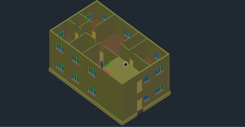
- Set the 3D_Wall layer to current and create a rectangle over the staircase and make it as region, Extrude the region to ht to 10' to make the staircase opening on top
- Place the 3'x7' wall over the back side of it so that the top floor can easily accessible
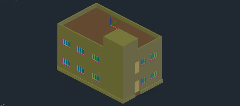
11. Creating Balconey and Front Design:
- Command "UCS" and place the ucs by face option over the front wall and set the 3D_Wall as current layer
- Create a rectangle of 6'' thickness and make it as region then extrude the rectangle to distance of 3'6''
- Then create a line using line command from the slab bottom to height of 3' over the balconey and also create a cirecle
- By using "sweep" command sweep the circle to the line so that balconey rail is created
- Then place the ucs on the bottom of the slab and keep the 3D_Balconey_Baluster to current layer create a rectangle on bottom and extrude to height of 2'6''
- Then by using command "CO" copy the rectangle and array it over the balconey, then create a circle over the rectangle and extrude it to 6'' height
- Then keep the front design as current layer and ucs to front view Create a rectangle and extrude the rectangle to 1' on the zero layer.
- Create a small rectangle over the front view and copy to certain distance, then extrude the rectangle to 1'.
- A Cantilever slab of length 2' and 9'' thickness is created and place over the window by keeping 3D_Cantilever layer as current and ucs to side view
- Then place the ucs over the front view and create a staircase by keeping 3D_Stair layer to current layer from plan create a rectangle and extrude the bottom rectangle to 6'', 12'', 18'' 24'' respectively from the bottom.
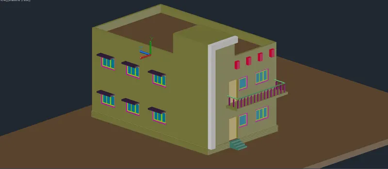
12. Setting Camera And Creating Views:
- Using the command " 3DO" set the angle of view to certain position and go to view tab > new view > name as - view1 > current display.
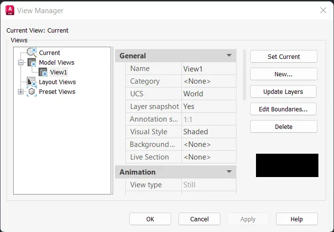
- Then go to the view manager and click on view 1 and set this view to set current and press ok.
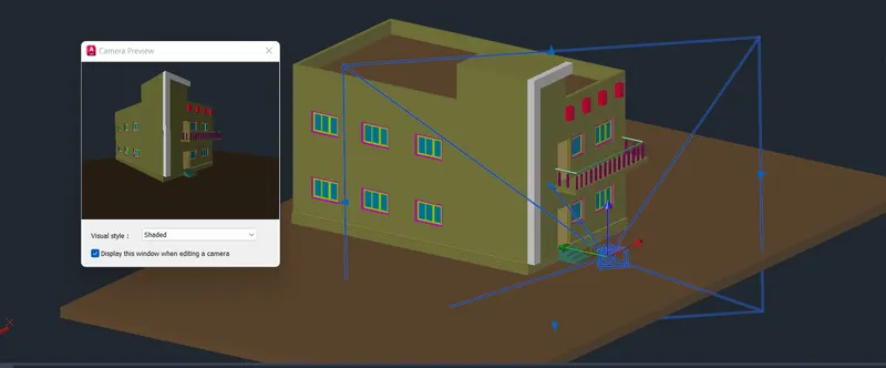
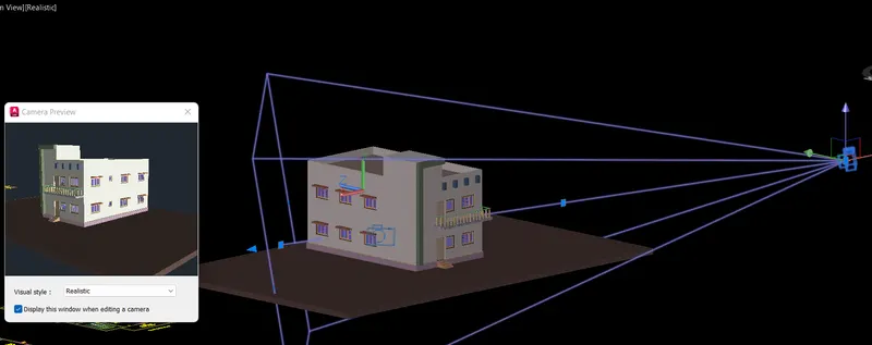
- For camera view create a circle over the floor area of diameter 2' and extrude the circle to height of 5'
- Then go to visualize tab and click on create camera and place the camera over the extruded circle press enter
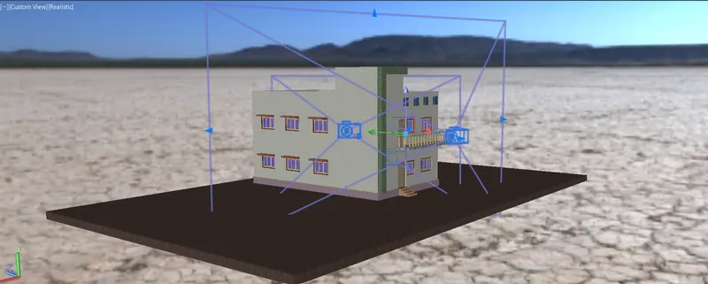
- Erase the circle and if you double click on the camera it shows a preview of the camera angle,set the visual style to - realistic
- The following camera angle preview is shown below,
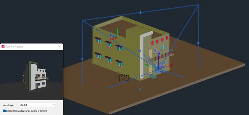
- Likewise create a 2 to 3 view by clicking viewtab > new view and save the view and set it as current in view manager
- Then again create a circle and extrude the circle to height of 5' and set the camera over the extruded circle
- A preview of camera view is shown in dialog box set the visual style to - realistic
- And distint light is also created.
13. Material Browsing and Mapping:
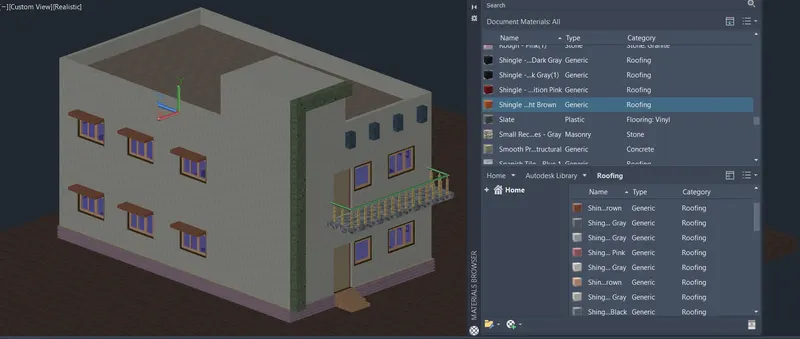
- Once the camera view is seted then assign the materials to each elements
- Keep the visual style in - Realistic style
- Go to visualize > render > material browser or command - "RMAT"
- A material browser and document dialogue box will appear.
- Then go to autodesk liberary select the material to stone and add the selected material to document material
- Double click the stone to open the edit box, edit the stone scale so that it should fit in the footing or pcc and easy to visualize
- Then select the object in plan and select the stone material right click and click on assign to selection, the selected object now assigned to stone
- Then command - "SETUV" to manage the color tone and mapping the material to fit the elements
- Like wise for all the elememts each materials are assigned
14. Setting Environment and Exposure condition:
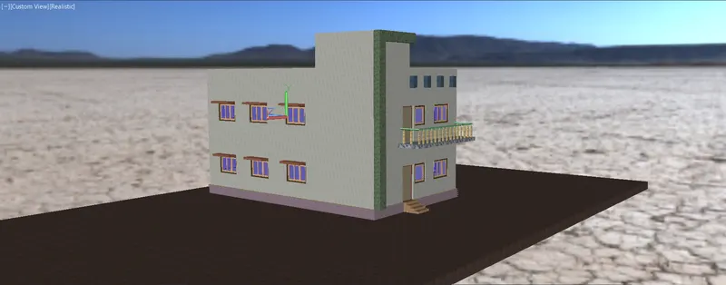
- After assigning all the materials from the material browser rendering process is carried out
- The environmental exposure is also set go to Visualize tab > Render > Render with environmental and exposure
- Click the environmental and exposure condition a dialog box will appear open set the environment - on , and click on image based lightning and set this to - Dry lake bed
- Adjuss the exposure and white balance for clear visibility
15. Rendering:
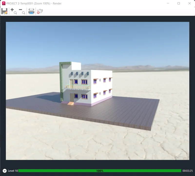
- After setting the environment and exposure rendering is done
- Command "RR" or go to Visualize tab > render > render preset manager > click on render
- A render dialog box will appear set the Render in - Window, Render size - 800 x 600 px- SVGA and name it as - copy 1
- Set the render level to - 10 and render accuracy to - High quality and select render, a rendering process starts
- once the rendering is done a clear image will appear save the image as jpeg format.
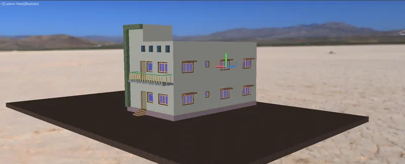
- The save image of a rendered residential building is shown below.
RESULT:
- Thus the required three dimensional model of the residential building is created
- Suitable materials are assigned to each elements
- Camera positions were properly set such that a proper view of the building is acquired
- Rendering is done.