Creating Kitchen layout, Hatching of Architectural elements and sectional view of an Industrial Building in AutoCad
AIM:
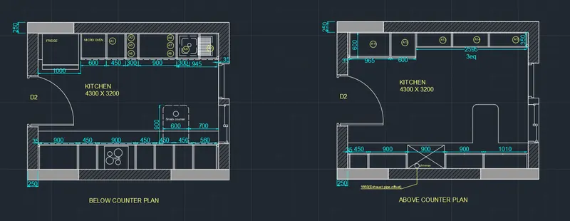
To create the kitchen layout and also use proper dimension techniques to dimension the kitchen layout
and also to inset the text wherever required
PROCEDURE:
- Open a new drawing with metric system
- Units are sets to mm
- limits and limmax are also set
- Then use zoom command
STEPS TO DRAW BELOW COUNTER PLAN:
STEP1
- In the command type rectangle of dimension of 4734 x 3688 mm to draw outerwall
- In the command prompt type offset and take the offset distance of 250 mm on each side and fillet the outer edges with zero fillet radius
- The dimension of door is assumed as 1000 x 2045 mm
- Use arc to draw the doors
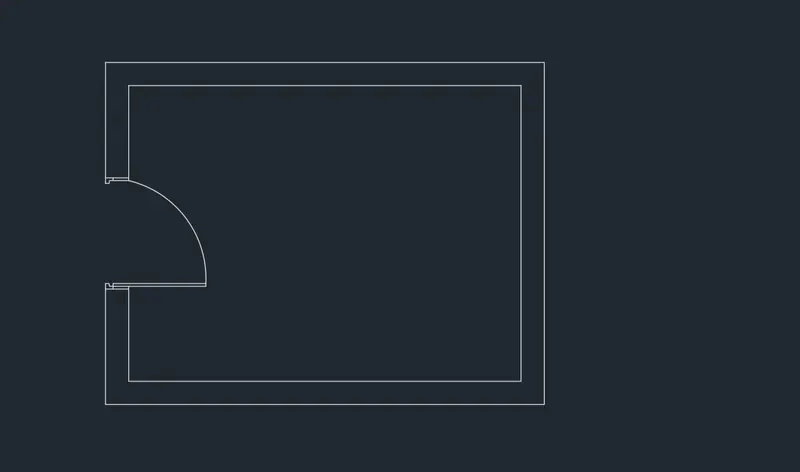
STEP2
- The kitchen cabinets are drawn using line command
- Offsets are done where ever required
- In the command type trim to trim the extra lines
- In the command prompt type offset at a distance of 35,350, 450, 900, 450, 450, and 560 respectively from left to right
- The doted lines are loaded and used
- Repeat same procedure to draw another sides
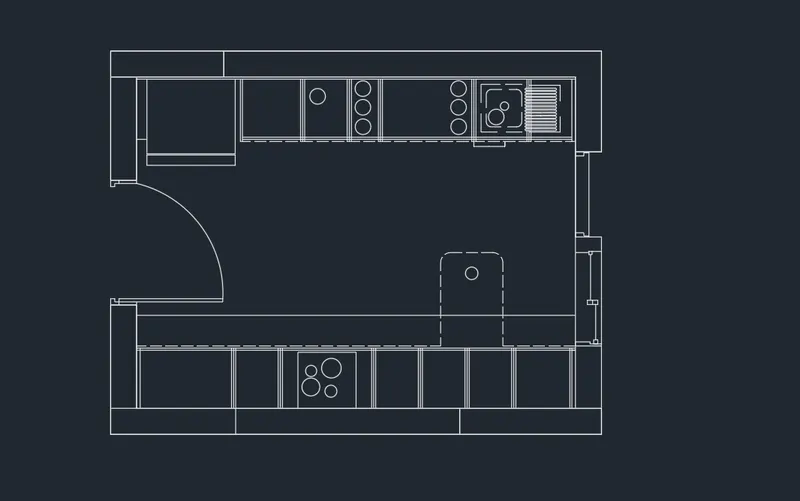
STEPS TO DRAW ABOVE COUNTER PLAN:
- In command prompt type line and draw a line of length 4300 in horizontal and 3200 in vertical directions
- Offset 250 mm towards all sides of rectangle outside the figure
- The kitchen cabinets are drawn using line command
- Offsets are done where ever required
- In the command type trim to trim the extra lines
- In the command prompt type offset at a distance of 35,350, 450, 900, 450, 450, and 560 respectively from left to right
- The doted lines are loaded and used
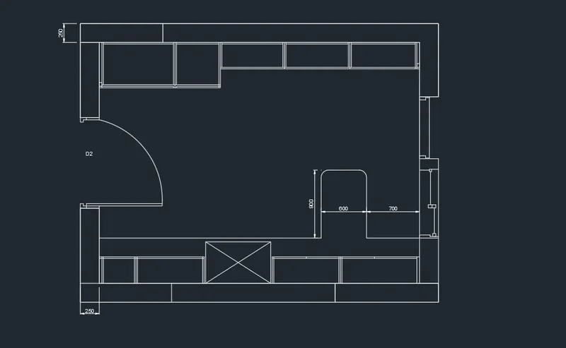
HATCHING THE LAYOUT:
- To hatch the outer layer in kitchen click on home tab - Draw panel - Hatch
- On the properties panel hatch type list, select the type of hatch that you want to use.
- On the pattern panel, click a hatch pattern or fill
- Pick points insert the hatch or fill within a closed area that is bounded by one or more objects
- Select the boundary objects insert the hatch or fill within a closed object.
- The selected hatch is retained until we change it.
- On the properties panel, we can change the hatch type or colors or modify the transperancy level, angle, or scale for the hatch until it fits into area
- On the expanded options panel, we can change the draw order to specify wheather the hatch and its boundaryare displayed in front or behind the objects
- You can also see the preview of the objects if the preview is okay press enter or press escape to go back to the edit hatch option
- Hatch the brick wall with ANSI32 and hatch other part as solid patten and grey color
DIMENSIONING THE LAYOUT:
- In command prompt type DIMSTYLE to edit the dimension style and text font
- Create a new type name it as arial set the arrow size and text height inorder to fit for layout
- Increase the over all scale gradually until the dimensions are visible clearly
- The specified dimensions are made either sides of the kitchen
- Then all the dimensions and text are placed in the respective named layers
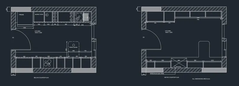
RESULT:
The kitchen layout below counter plan and above counter plan are drawn as shown and dimensioning are placed with proper dimension techniques
Q2-
AIM:
To create the elevation of the plan and apply proper hatch in the walls, doors, windows, and otherarchitectural elements
INTRODUCTION:
- An elevation drawing is drawn on a vertical plane showing a vertical depicition
- Specific type of drawing used to illustrate a building or portion of a building
- Elevation drawing are orthographic projection
- This is the most common view used to describe the external appearence of a building
COMMANDS USED:
- Command - unit
- Command - Limit
- Command - Line
- Command - Offset
- Command - Trim
- Command - Rectangle
- Command - Dimlinear
- Command - DCO
- Command - Move
- Command - Copy
- Command - Block
- Command - Insert
PROCEDURE:
STEP1
- Open a new drawing file with metric system
- In the command prompt type units, select the unit to decimal and set precision to 0
- Then command Limmax and set the maximum upper cornor as 12000,12000
- The use the zoom all command
STEP2
WINDOW DRAWING
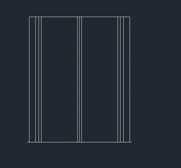
- According to the standards the window size is taken as 1000 x 1200 mm
- Draw a rectangle of size 1000x1200 mm, then in command type offset and take the left vertical line offset to a distance of 40, 70, 35, 25, 510,20
- After offseting on the left side mirror the lines on the other side by using MI command
- Both the lines on extreme ends are deleted
STEP3
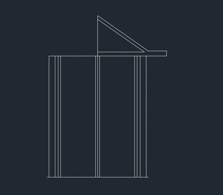
- Then from top right corner draw a horizontal line of about 200mm and vertical line of 60 mm then again 200mm
- From here Draw a inclined line at 30 degree towards the mid line and offset the inclined line to 30 mm
- By using MI command mirror the object on left side also
STEP4
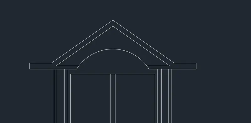
- After mirroring draw the arc using arc 3 point tool
- Pick the first point of the arc from top right side end corner at distance of 150 mm and the second point of the arc as the mid of the rectangle and third point of arc as 150mm from left end side corner
- Then draw a inner rectangle of dimension about 750 x 1050 mm
STEP5
Make the windows as a block
- To open a block tab use command B
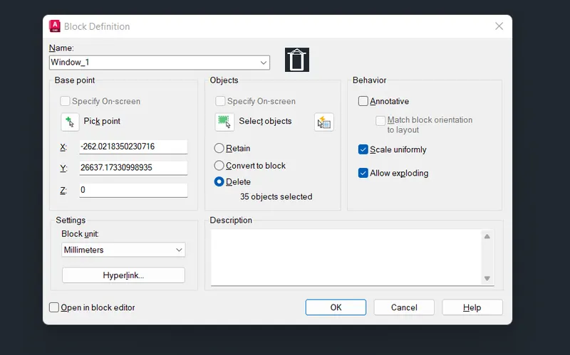
- For that in command prompt type B enter a block definition dialog box will be opened Save the name as- Window_1
- Then click on specify the point i,e Specify the centroid of the object then give the default values , and select the entire object a preview will be shown. enable scale uniformily and allow exploding option
- As we can select any one of the following option Retain, convert to a block, or delete, here i selected convert to a block which means the block itself will get converted and remains as such in display.
- If we select retain option the object will be retained and same as the actual drawing and a block is created for the objects that have selected. If we you the delete option Then the converted block in the drawing gets deleted
WINDOW 2:
STEP1
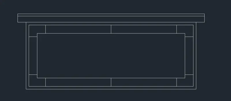
- Draw a rectangle of length 3200 mm and width as 1200 mm
- Then type O in command and offset the rectangle to inner side for 50mm then again offset for 350 mm
- On the outer edge extend the line to 150 mm horizontally and vertically on both side of rectangle
- From the inner rectangle keep corner at a base draw a line vertically towards the second rectangle at distance of 150mm at each corner follow the steps
STEP2
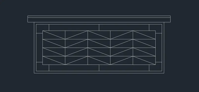
- Explode the inner rectangle and offset the vertical line by 550 mm each for 4 times to make 5 columns
- Similarly offset the top horizontal line to 250 mm to make 4 rows
- By using line command draw a inclined line connecting all corners which shown below
STEP3
The created window is now converted into blocks
- To open a block tab use command B
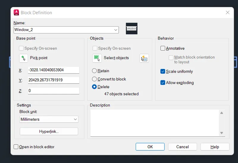
- For that in command prompt type B enter a block definition dialog box will be opened Save the name as- Window_2
- Then click on specify the point i,e Specify the centroid of the object then give the default values , and select the entire object a preview will be shown. enable scale uniformily and allow exploding option
- As we can select any one of the following option Retain, convert to a block, or delete, here i selected convert to a block which means the block itself will get converted and remains as such in display.
- If we select retain option the object will be retained and same as the actual drawing and a block is created for the objects that have selected. If we you the delete option Then the converted block in the drawing gets deleted
BALCONEY DRAWING:
STEP1
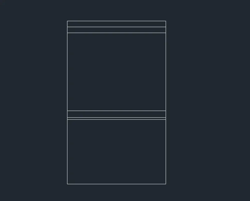
- Draw a rectangle of length 1250 mm and width 2070 mm
- Then explode the rectangle and offset the top line to 150 mm respectively
- On bottom line take offset and give distance of 850, 20, 60 mm respectively
STEP2
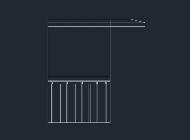
- On right top corner draw a line horizontally for 750mm and again vertically for 50 mm then close the rectangle
- From top line draw a line of 450mm and connect the rectangle with inclined lines
- With help of line command diagram draw the bottom post and Copy them
- In command prompt type O and give the offset distance of 150 mm respectively until it reaches the other side of the line
STEP3
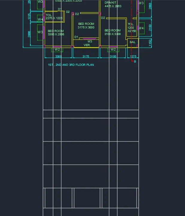
Project the line from the plan using construction at edge of the wall and corners of the windows
STEP4
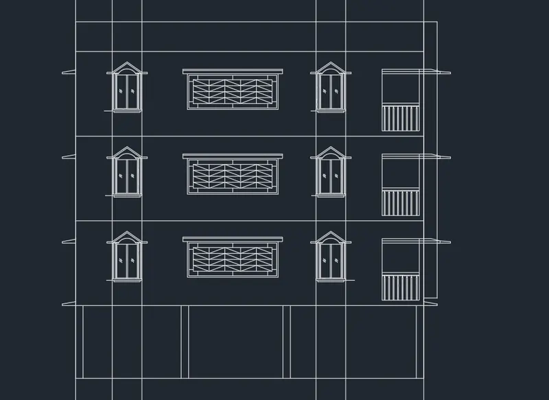
- Drwa a line horizontally connecting two extreme ends of wall it is refered to as ground level
- Make a offset of 125mm from the ground level
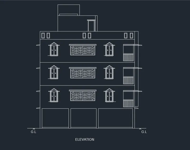
- Then again take the offset continuousily at a distance of 2450, 2850, 2850, 2850, 1000 mm respectively from the ground level
- By INSERT command insert the window from bottom at a distance of 850mm above the 2450 line, so that the bottom end of the line should possess a gap of 850mm
- Similarly insert all the windows from 850mm above to their respective floor levels
- And project the lintel as a sunshade on either side of the buildings
- Place the balconey at the lintel levels each balconey should palce according to the figure
Step5
- Offset 2500 from terrace level to mumty
- Then offset 600 and 1200 for O.T.H
- And place a door offset the door to 100mm on all sides
STEP6
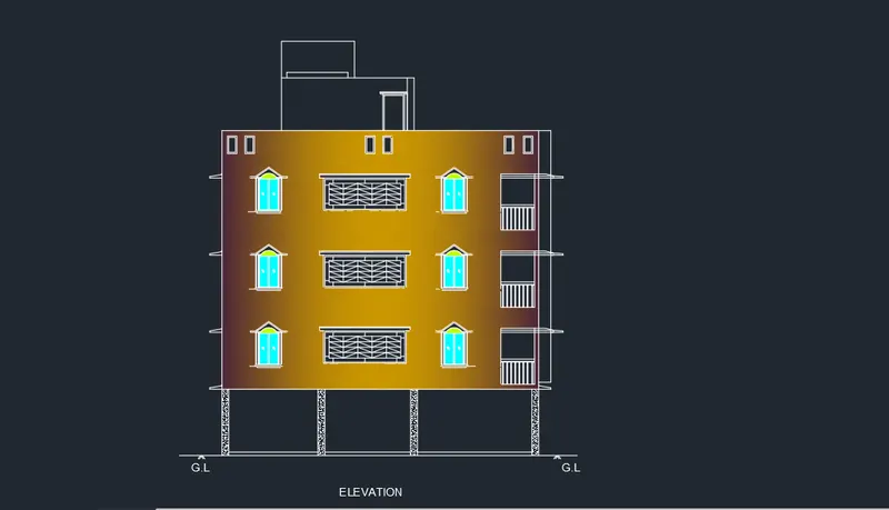
- Using Hatch command hatching is done in bottom by keeping AR-CONC as petten and fill the column with ar-conc by keeping scale value to 1
- Then for exterior wall i have used the gradient as hatching gicing two colors and adjuss the transperancy and by using pick point i have hatched the outer wall
- And for windows i have used the hatch type as SOLID and color -cyan for pannel and green for window elevation
- Then By using multiline text command the texts are placed
RESULT:
The elevation is drawn along with using proper hatch techniques for walls, doors, and windows.
Q3-
To create a sectional view of a building as shown and to provide proper hatch and dimension techniques.
INTRODUCTION:
- A sectional view is the part of the object remainng after a portion is assumed to cut or removed
- The purpose of section view is to show the interior detail or space
- By taking imaginary cut through the object and removing a portion, the inside features may be seen clearly.
COMMAND USED:
- Units
- Limits
- Line
- offset
- trim
- Dimlinear
- Dco
- Mtext
- Dimstyle
- Move
- Copy
PROCEDURE:
STEP1
- Open a new drawing with metric system
- Units are sets to mm
- limits and limmax are also set
- Then use zoom command
STEP2
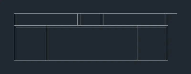
- Using Xline command draw a horizontal and vertical construction lines
- Offset the construction line horizontally at a distance of 25300mm
- And offset the horizontal line vertically to a distance of 5850 mm and 2000 mm respectively
- Then from left end the following offset is made 5315, 5320, 3900, 4720, 1020, 5025 respectively
- By using trim command trim off the extra projected lines
- Then offset the middle vertical line to 150mm on either side and delete the middle line to make a whole of 300 mm and by using line command project the lines towards top trim the line in pump room area
- Offset the left side corner to 150mm on both side to make 300 mm wall this wall is upto pump room and for above offse to 450mm on both sides
STEP3
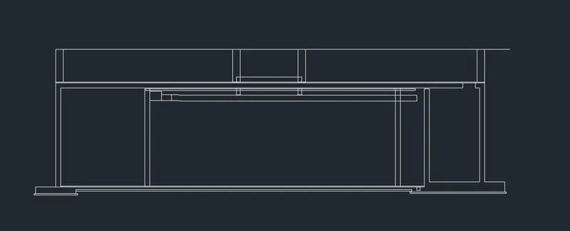
- Fire pipe line is drawn at a distance of 50mm below the top concrete beam
- And from 100mm below the same a duct id made to a distance of 750 x 550 mm
- Again from the bottom wall at a distance of 200mm a line is drawn from the duct towards right
- Maintain a spacing of 25mm between the duct and concrete beam
- From bottom line offset a distance of 50mm below the 5850 line
- On left side wall draw a line of 1200mm and 200mm then 2400mm to create a rectangle basement similary on the right side also
Step4
- From 6150mm line from bottom draw a line along with this line at a distance of 300mm and project it to a certain distance on right side at both sides
- Then sprinler is drawn on the left side at the distance of 100mm from left fire pipe end
- Copy the sprinler as shown and place it
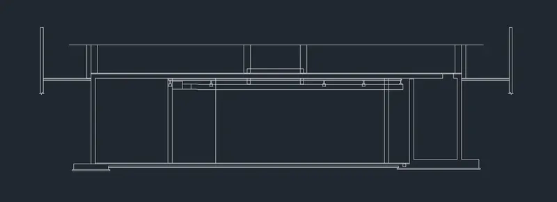
Step5
- In command type H and set the patten to AR-CONC, hatch the portion by suing pick point method as shown
- And hatch the bottom end with solid and ANSI31 and adjuss the scale for visibility
- Then command DIMSTYLE and MLEADERSTYLE and set the annotaions and text height the font used is - Arial
- DIMLIN and DCO command are used to dimension the length and MLEADER is used wherever required as shown
- Layers are created, place all the texts and annotaions in the layers
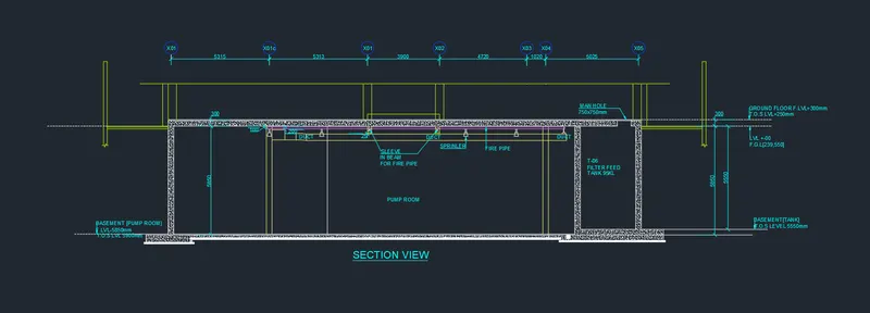
RESULT:
The section view of the industrial building is drawn, dimensions and hatches are done as per the figure.