Project 1 _Creating an Architectural plan for the provided plot size and develop relevant basic structural drawings
Design and drafting a layout of a residential building with the following details:
a. Plot size: 60' x 20' (18.3mx6m)
b. Orientation - Facing East
c. Develop the following:
1. Architectural drawing (Floor plan, Elevation, and Section)
2. Structural Drawing (Column, Beam, Footing Plan)
AIM:
To create a architectural drawing consisting of Floor plan, Elevations, and sections for the plot size 60'x20' and also create the structural drawings for column, Beam and Footing.
INTRODUCTION:
The Architectural and Structural drawings are designed according to the Vaastu shastra and drawn in AutoCAD using various commands and tools.
Vasstu Shastra:
- It is an ancient indian science of architrcture and acts as guideline to design our home to enhance positivity
- Vasstu is done to maintain positivity all over home and to life peacefully without negative vibrations
- The effects of sunrays, wind flow, pull of earth's magnitude and other energies
- A good home should radiate good energy for that we going with vastu while designing
- This vastu is not possible in construction of appartment buildings etc,
Significance of eight directions:
- Four cardinal directions East, west, north, south
- Four non cardinal driections are Northeast, southeast,northwest and southwest
- North is represented for - Wealth
- South is represented for - Dharma
- West is represented for - prosperity
- East is represented for - prosperity
Directions as per vasstu:
- Kitchen - South-east is prefered direction, North-east should be avoided
- Staircase - South-west is the best direction, North-east should be avoided
- Toilet - North-west is the best direction, North-east must be avoided
- Master room - South-west is the best direction
- Guest room - Noerth-west is best direction
- Storage room - North-west is best
- Living room - North-west is best direction
- Overhead tanks - West is the best direction
- Under ground tanks - North-east is best direction, South-west avoided
- Borewell - North-east is suitable
1.Plot size - 60' x 20'
2.Orientation - East Facing
COMMANDS USED:
- Units
- Limits
- Zoom
- Layers
- Construction line(XL horizontal and XL vertical lines)
- Polyline
- Line
- Multiline text
- Multileader
- Offset
- DText
- Dimlinear
- Dimcontinue (DCO)
- Hatch
- Copy
- Fillet
- Trim
- Move
- Erase
DRAWING PROCEDURE:
- Open a AutoCAD software and give command STARTUP and open new drawing of start from scratch
- Command UNITS and set the units to Engineering and precision to 0'-0.0''
- Then command LIMITS and give the limit of lower left corner to (0,0) and upper left cornor to (500',500')
- Go to layers properties > create a new layers for reference > close
Architectural drawings:
1.Plan
2.Elevation
3.Section
Structural drawings:
1.Column layout
2.Footing layout
3.Beam layout
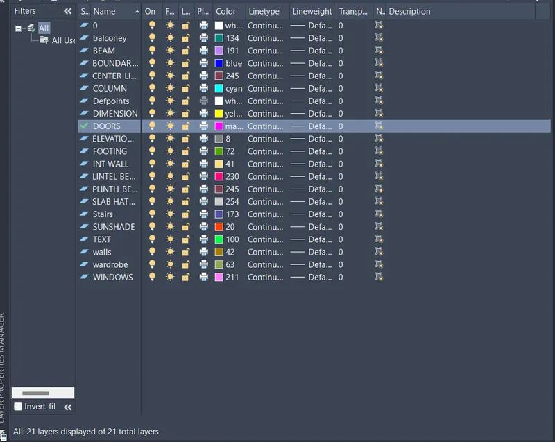
Create the layers by typing LA in command prompt
so that all the elements can easily be controlled and identified accordingly
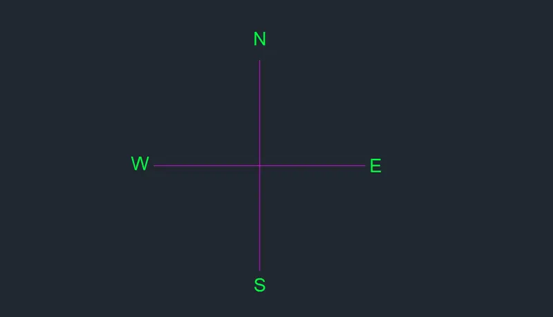
- Using the line command the direction lines are drawn
- And by multiline text command the directions are marked
- Then, using BLOCK command make this element to a single block and named it as directions
ARCHITECTURAL DRAWINGS:
1. PLAN:
- Using construction line command create the lines in x and y directions and trim the bottom and side line
- The building main entrance is facing in East direction.
- Using the line command and offset starting from east direction towards west the offset is done
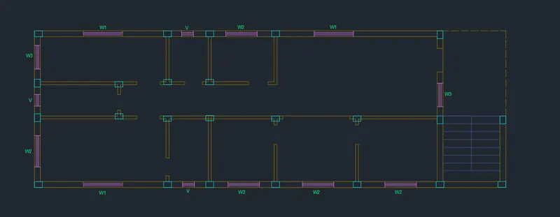
- Starting from the east , the car parking is planned at 8'x10'-10.5'', and stairs for about 8'x8'-4.5''
- After car parking and stairs our remaining floor area dimensioning to 15'-6'' x 18'-6'' including internal walls
- The thickness of all outerwall is about 9'' and the thickness of internal wall is about 4.5'' is provided
- For the parking are the line type is changed to SHORT-DASH and scale is adjusted for better visibility
- Then in command prompt type offset and at each 4.5'' wall the following offsets are made to create the rooms towards west direction 10'x8', 10'x8', 8'x5'-9'', 5'x8', 16'x8' are taken.
- And the kitchen, dining room, kids room, toilet and master bed room are drawn respectively
- This plan is drawn as per the vaastu, those planned directions are as follows
Main Door - East
Staircase - South-East
Kitchen - South-East
Living Area - Facing East
Study Room - North-East
Dining Room - South-East
Master Bed Room - SouthWest
Master Bed Toilet - South-East,North-East is avoided
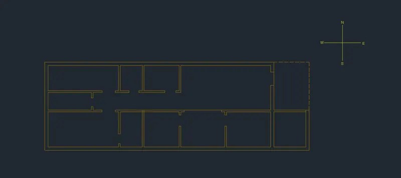
- The room dimensions are assumed as per the requirements
- Then, using the line command and trim command and extend command the doors are assumed drawn as per the required
- The drawn door dimensions are shown below in tabular form,
DOORS SIZE
D 3'x7'
D1 2'-2''x7'
D2 2'-6''x7'
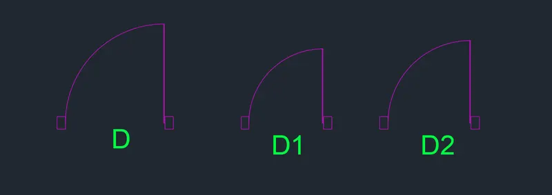
- Using the above door dimension the doors are trimmed and placed in the drawings
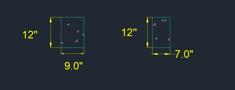
- Then, using the line command the column size are created for the size of about 9''x12'' and 7''x12''
- Then using the hatch command, the column is hatched with AR-CONC and the scale is adjusted to 1 for better visibility
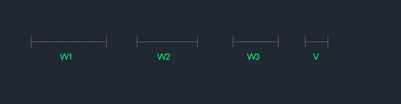
After the column is drawned then the windows are made for the following sizes,
WINDOWS / VENTILATORS SIZE
W1 5'x4'
W2 4'x4'
W3 3'x4'
V 1'-6''x1'-6''
- The windows are drawned as per the above mentioned dimension and are plotted and placed in the plan as per requirement
- The size of the footing - 4' x 4'
- After placing the windows draw the sunshades.
- Place the columns, windows, ventilators, in the plan
- The staircase are drawn using the line command and offset command, with tread - 12' and riser- 9'' and landing is provided at 1'-4.5''
- In the command prompt type DIMSTYLE and manage the dimension style, arrow head style and size of arrow
- Then create a new text style font with Arial as font style and adjuss the text height for better visibility
- Using the multiline text command the internal rooms and dimensioned are named and marked respectively
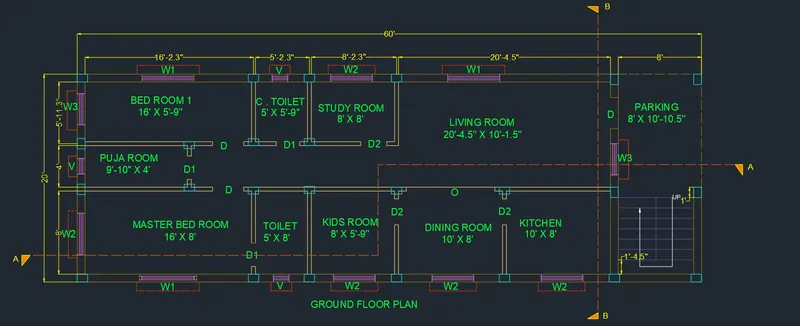
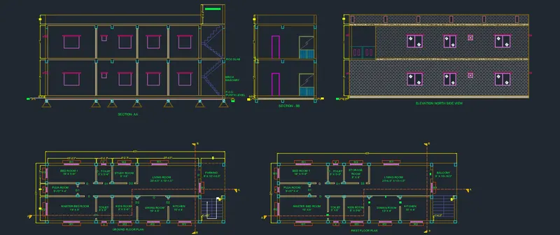
- After creating the ground floor plan the section is created using the line type ACAD- ISO02W100 long-dash short-dash the section is divided into two parts , SECTION- AA, SECTION - BB
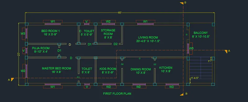
- And in the similae way the first floor plan is also created with small changes
- Storage room and balconey is provided in the place of study room and parking
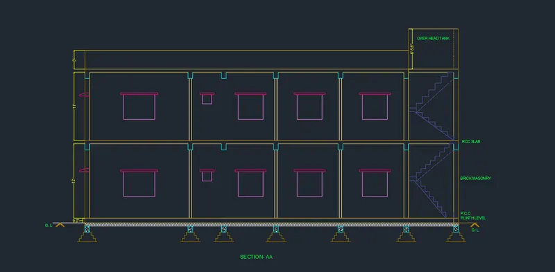
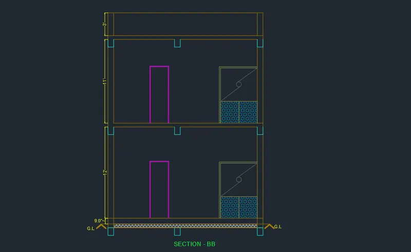
2.SECTION- AA:
- Using the command line, polyline, trim, and offset the following sectional view for the section-AA is drawn as per the plan
- From the ground level the PCC plinth beam, slab and overhead tanks are provided
- Then, place the columns at all the edges of the wall
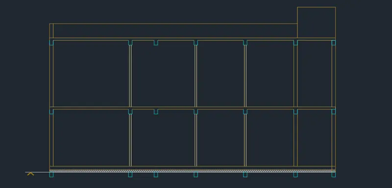
- Draw the windows as per the plan, and kitchen space as per the plan, and also staircase space
- Provided lintel beams over all the windows
- Provided the parpet wall which is of 3' height and overhead tank as well
- Then the staircase is drawn from the ground level, the tread of the stair is 12'' and the rise of the stair is 9''
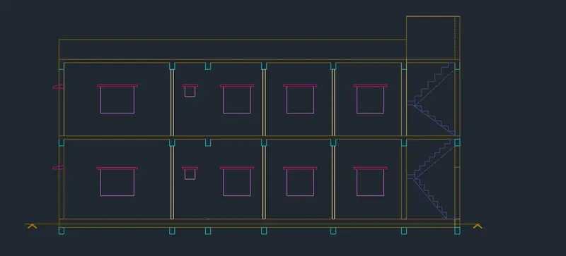
- Using DIMLIN command and DCO command the dimensions are made
- And using the DTEXT command the RCC slab level, lintel beam level, brick masonry, P.c.c plinth level are dimensioned and market
- Then in command prompt type HATCH and set the hatching to BRICK and the plinth level is get hatched after placing the bricks the scale is adjusted for visibility
2.SECTION-BB:
- Using the commands line, polyline, offset, fillet trim and hatch the section-BB is created
- The offset area for doors line and wall spacing is drawn as per requirement
- Copy the colum which is drawn in section and placed where ever required
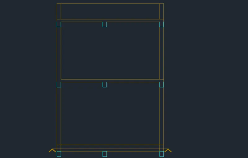
- After outerwall is made, then the doors are drawn for the required sizes
- Providing wardrobe with STAR hach commandand adjuss the scale for
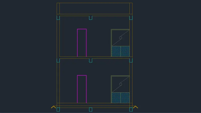
- The dimensions are marked at the side of the drawings
- And using HATCH command the P.C.C plinth beam is sketched with a brick
- Using multiline text command the the section are texted and then the ground level is marked
3.ELEVATION:
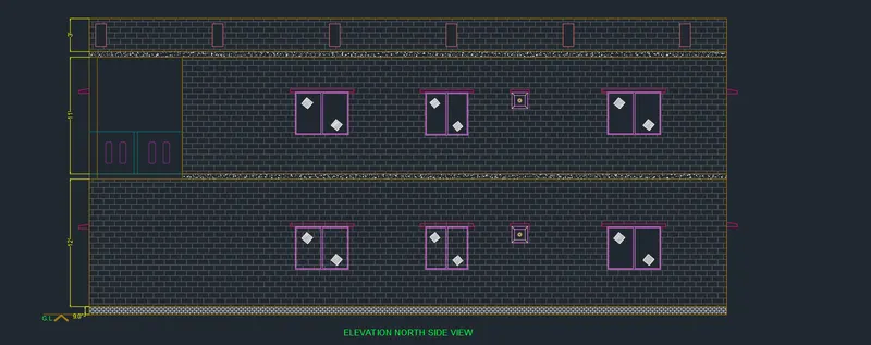
- Using the commands line,polyline, offset, trim and fillet the sectionalview of elevation is drawn from north side view
- Using the commands line, polyline, offset, fillet trim and hatch the sectional viiew of elevation is created
- In command prompt type offset and provide spacing between rooms and balconey
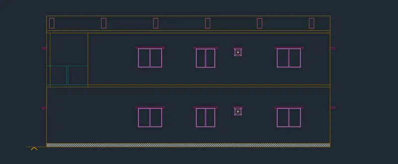
- Provided windows as per the plan, Chajja as per the plan and door as per the plan
- Provided lintal beam over the windows
- Then, the parapet wall is drawn at a distance of 3'
- Using the hatch command create the super-structure below the parapet wall with brick and adjusted the scale of text
- Using hatch command , the P.C.C plinth level and the R.C.C slab level is market
- Then the thickness of slab is 6'' is hatched with AR-CONC and adjuss the scale for better visibility
- For walls command HATCH and set the hatch to BRICK and set the value to 25 for good views
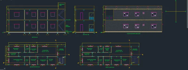
- The following image shows the Ground Floor plan, First floor plan, Side Elevation and Sections AA and BB all together
STRUCTURAL DRAWINGS:
1.Column layout:
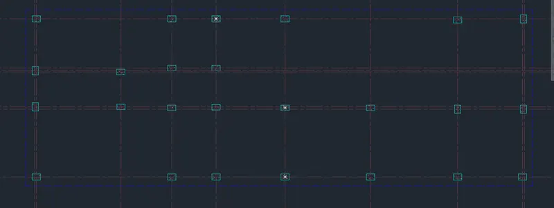
- Turn off all the layers except the column layer in the layer properties
- Select the copy tool by typing CO in the command prompt
- Select all the columns from the building ground floor plan and copy them to a seperate location as shown in below
- Select the construction line tool by typing XL or Xline in the command prompt
- Then select the line type as ISO 02W100 and gave the scale as per requirement
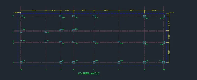
- Draw the lines through the midpoint of the columns in the horizontal and vertical directions as shown in the above figure
- Select the trim tool or in command prompt type trim the extra lines extending from the layout
- Select the dimension tool or type DIMSTYLE to alter the sizes of building for better visibility
- Select the multiline text coammand and dimension the Column layout and the number of column are marked as C1,C2 etc,
- Modify the dimension as per the requirement
- Then change the color of the dimension and extension line as per requirements and give the text height to 8''
- After setting the dimstyle manager dimensioning is done at all the sides
2.BEAM LAYOUT:
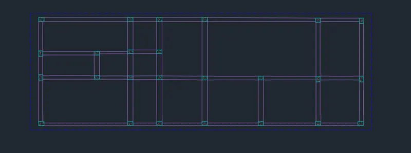
- Turn off all the layers except the column layer in the layer properties
- Select the copy tool by typing CO in the command prompt
- Select all the columns from the building ground floor plan and copy them to a seperate location as shown in below
- Turn off all the layers except the column layer in the layer properties
- Select the copy tool by typing CO in the command prompt
- Select all the columns from the building ground floor plan and copy them to a seperate location as shown in below
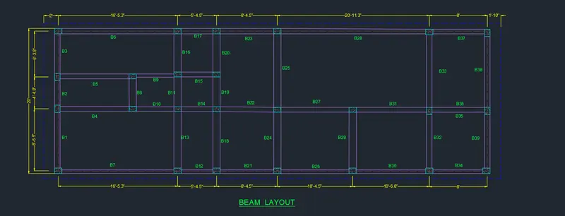
- Select the dimension tool or type DIMSTYLE to alter the sizes of building for better visibility
- Then change the color of the dimension and extension line as per requirements and give the text height to 8''
- Modify the dimension as per the requirement
- Select the multiline text coammand and dimension the Column layout and the number of beams are marked as B1,B2 etc,
- After setting the dimstyle manager dimensioning is done at all the sides
3.FOOTING LAYOUT:
- Turn off all the layers except the column layer in the layer properties
- Select the copy tool by typing CO in the command prompt
- Select all the columns from the building ground floor plan and copy them to a seperate location as shown in below
- Turn off all the layers except the column layer in the layer properties
- Select the copy tool by typing CO in the command prompt
- Select all the columns from the building ground floor plan and copy them to a seperate location as shown in below
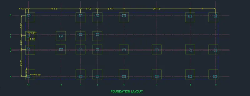
- Using the line command the square footing of size 4'x4' is provided for all the column,Except for the stair case 3'x3' is provided
- Using the centre line type ACAC-ISO08W100 the column centers are marked
- Type DS in command box dimension setting dialog box will open create a new setting with a new font style and text height as required here the text height used is 8''
- Using the DIMLIN command and DCO command, the dimensions between the grid lines are mentioned
- Also using the the column position in the footing is mentioned
- Using MTEXT command, the grid name and title is mentioned
- In the command prompt type DIMlINEAR and then select the first point and second point of the object to be measured followed by DIMCONTINUE command
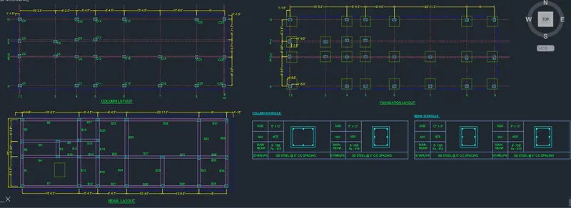
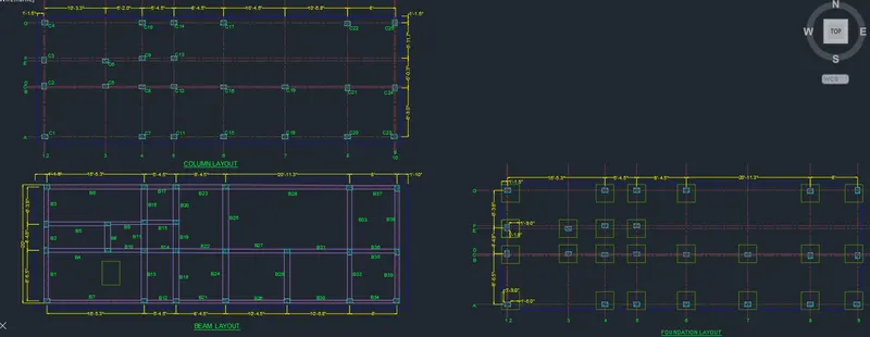
The following image shows the Column layout, Footing layout, and beam layout together
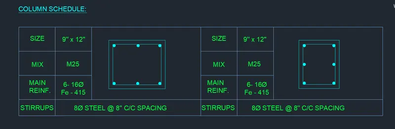
1.COLUMN SCHEDULE:
The column schedule is the schedule in which the details of column will be collected in the construction for design purpose
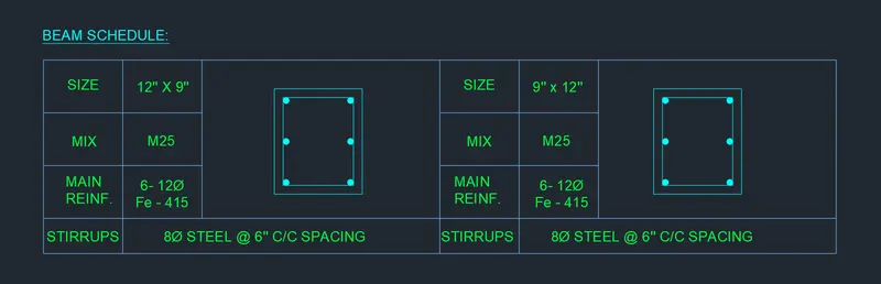
2.BEAM SCHEDULE:
3.FOOTING SIZE:
Footing size is 3' x 3'
RESULT:
The Floor Plan, Elevation, and Section of architectural drawing and the Column Layout, Beam Layout, and Footing Layout of Structural drawing of size 60' x 20' is drawned