Project 2_Creating a 3D rendered model for a Residential Building in AutoCad
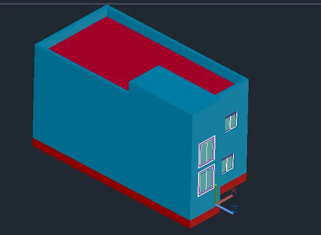
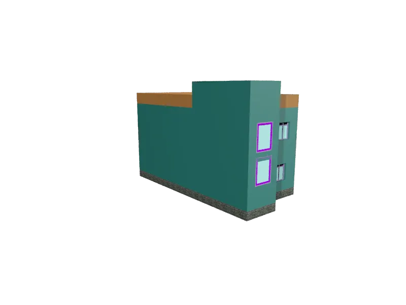
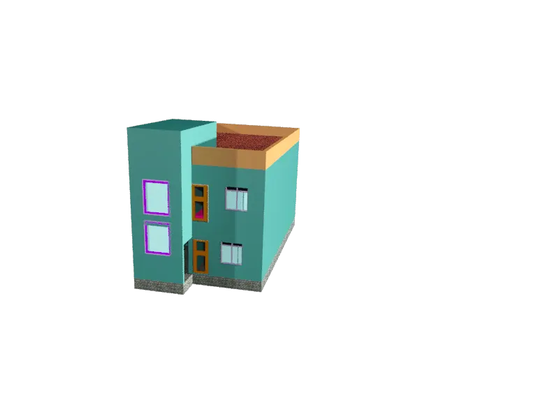
AIM:Create a 3 dimensional model of the residential building with a rendered view.
INTRODUCTION:
The process of creating any surface of an object in three dimensions by using special software is called 3D modeling. A 3D model can also be represented as a two-dimensional image by using the 3D rendering process.
types of modeling:
- Wireframe modeling is useful for initial design iterations and as reference geometry, serving as a 3D framework for subsequent modeling or modification.
- Surface modeling offers fine control over curved surfaces for precise manipulation and analysis.
- Solid modeling is efficient to use, easy to combine primitives and extruded profiles, and offers mass properties and sectioning capabilities.
ues of 3D modeling views:
- change between different visual styles such as Conceptual, Realistic and X-Ray
- Switch between parallel and perspective projection
- Choose between standard preset views such as Top, Front and isometric view.
command in 3D modleing:
- extrude
- box-box,cylinder,cone.
- region
- boundry
- slice
- sweep
- loft
- revolve
- union
- subtract
- intersect
- extrude faces
- separate
- section plane
- UCS
- camera
- materials browser
- rendering
PROCEDURE:
- open autocad 2021 file and select impherical.
- set the units to engineering with precision 0'0.0".
- set the limax as 100',100'.
- zoom command and set all.
- set the view to top,keep ortho and osnap ON.
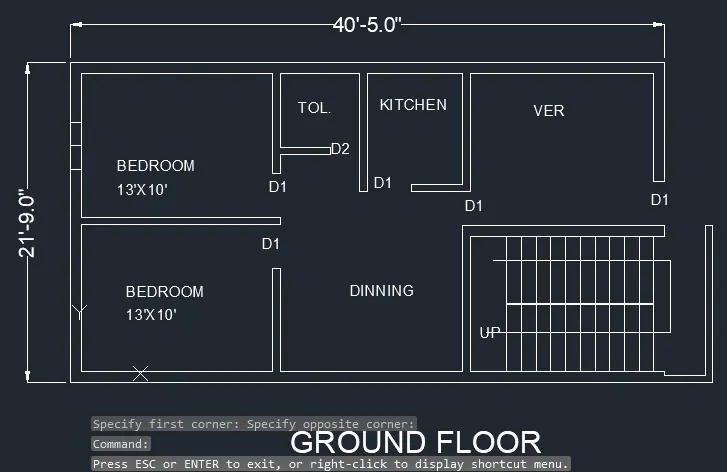
- plan the ground floor plan fo area 21'9"x43'8".
- exterior wall thickness be 9" and interior thickness 6".
- bedrrom dimension-13'x10',kitchen-6.5'x7'8",toilet-5.5'x5'.
- dinning-13'4"x13',ver/first floor bedroom-12.5'x12'7".
- door 1 D1- 3'x6.8',D2-2'x6'.
- window diemsion W1-4'x4'6".staircase window dimension-4'10"x6'.
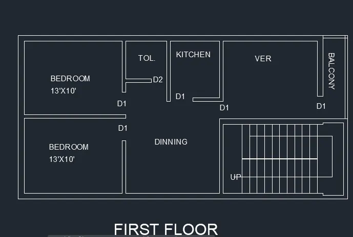
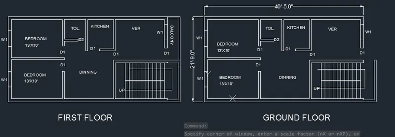
- for elevation,parapet wall be 3' height.
- plinth level be 2' and height of buildig from plinth beam is 22'.
- gate dimension be 9'2"x6'8".
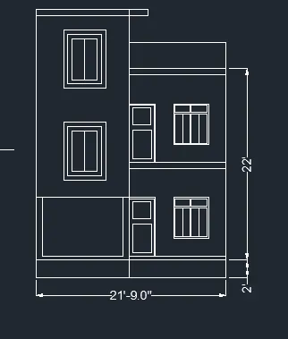
- make layers for wal,window,door.
- remove the dimension and text.
- enter boundry command and make region keeping wall layer as current.
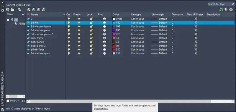
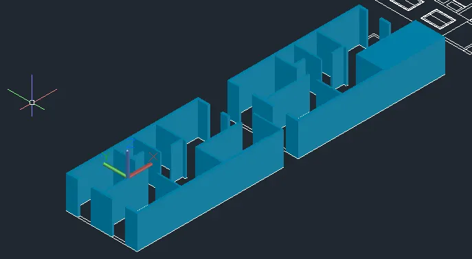
- extrude the the wall upto 10'.
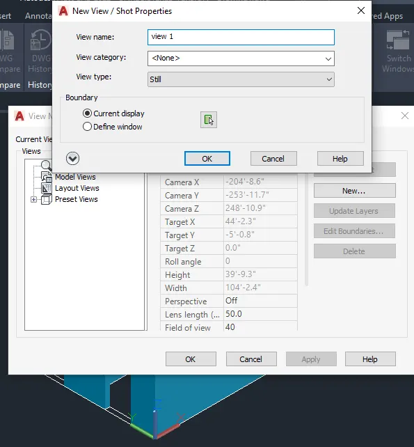
- set the view and same it.
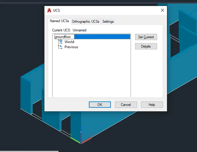
- also enter UCS world nd set the icon and save the usc in usc maneger command.
- for door and window make rectangle in window layer,make it a region using boundary commandand copy to heights of silllevel and top.
- now extrude the recatngel to silllevel and top rectangle downwards.
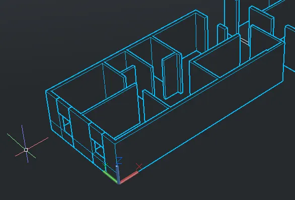
- repeat the same for first floor also.
- now for making window frame,panel and glass.
- copy the elevation and make a group of one copy.
- move the group at plan section and rotate in YZ axis at 90 degree.
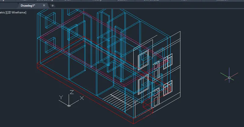
- from a copy of elevation,use boundry and subtact command.
- make a region of frame and subtact from smaller rectangle.
- similarly for next rectangle and last for glass.
- similar procedure for door frame and staircase window also.
- after making region extrude each recatngle of window in -ve y-axis.
- similarly for doors.
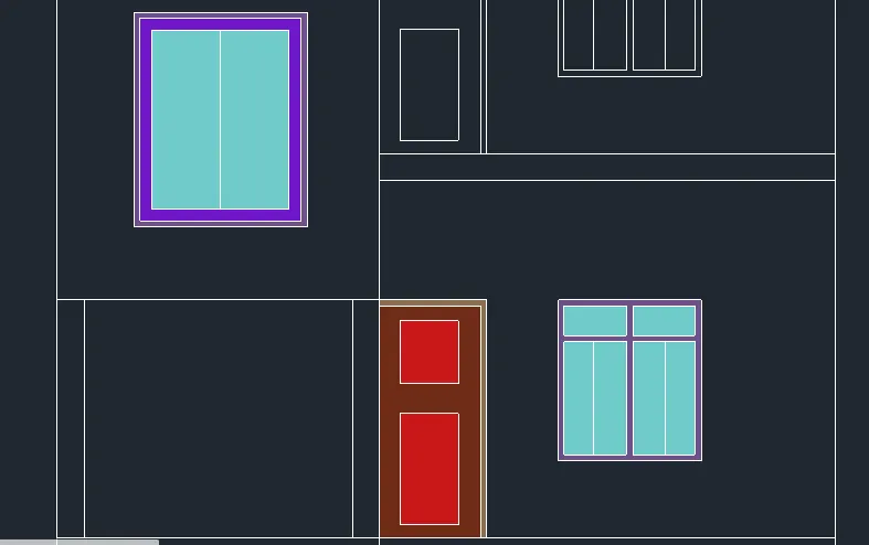
- now make a group and copy paste in extruded plan section.
- similarly copy the same for first floor plan.
- now for making staircase,make a region and extrude to the height adding 6" extra for every step
- select all and make a union and extrude the landing.
- copy paste the same for next stairs.
- select the staircase and paste in ground and first floor.
- for plinth level,extrude 2' downwards.
- for parapet wall,extrude the wall upto 3' height .
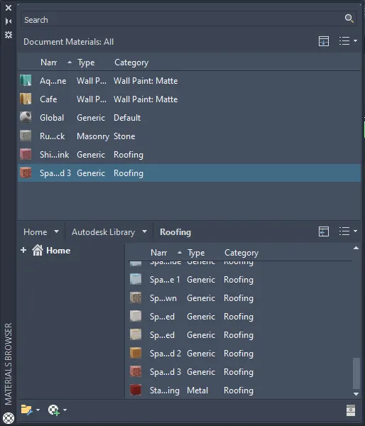
- for materials,select material browser from visualize panel or enter MATBROW.
- assign the specific materials.
- draw a circle of certain radius and extrude upto certain height.
- click on create camera and place of the extruded circle.
- name the camera and adjust the view.
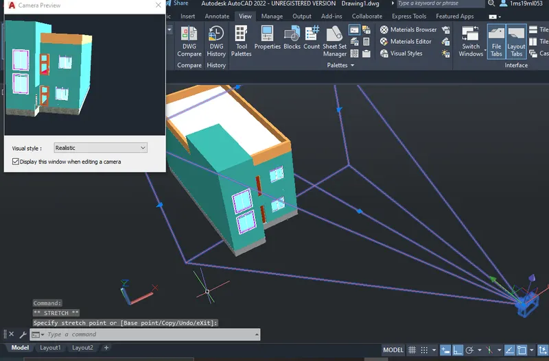
- similar way provide distant light .
- speicfy view and enter rr to begin the render opertion.
- save the file to the desktop.
RESULT: