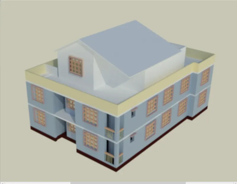
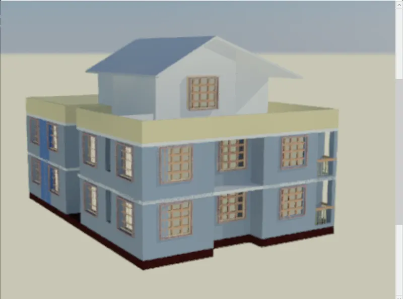
Project 2_Creating a 3D rendered model for a Residential Building in AutoCad
Project 2
AIM: To create a 3D rendered model for a Residential Building in AutoCAD
INTRODUCTION:
3D Modelling of the Given objects are Drawn by AutoCad from three dimensionsal aspect by showing size, area, Height, surface and Texture from various tools such as Line, Rectangle, Loft, Extrude, subtract, union, UCS, Region, Boundary and other tools
The main objective of this project is to understand about to create a Plan in 2D, then convert it into 3D using AutoCAD 3D, applying materials and rendering.
AutoCAD is primarily used for generating 2D drafting models, While it is possible to create 3D objects, There is a wide range of pre-defined 3D objects in AutoCAD. AutoCAD 3D commands like Extrude, Sweep, Revolve, and Union are very essential while generating an object.
Also, the user must know the importance of the Viewport feature if they are working on 3D Models. The viewport command allows the user to split the drawing area into different windows to project multiple views of the model. These include the top, front, left/right views of the object. This feature works great for the user and helps them to observe the model from different aspects.
Tools used for Rendering a Complete 3D model includes all those 2D ans 3D basic Tools which is Essential in drafting the plan from the Begining from a Line to Visualization of the Project.
To Cancel Selected Command Press “ESC”
To Invoke Previously Selected Command Press “ENTER”
Use UCS option Convienently for the seamless Drafting Experience
To Change the View settings to 2D, Shaded, Realistic etc,. as per Convieniece during Creating 3D Objects
PROCEDURE:
Go to START MENU, select AutoCAD 2022.
In the Command line type in: STARTUP
Enter new value of startup: 1
Go to Application Menu and select New
In the 'Create New Drawing' dialog box, we do the Advanced Setup and select the 'Decimal' unit of measurement and select precision as 0.00
Enter 'UNITS' command in the command tab.
In the Drawing Units dialog box, select 'Decimal' in Type 0.00 in Precision; and 'millimeters' in Insertion scale.
Got to AutoCad menu Click on Import option and import a Plan
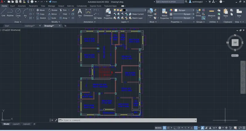
Select all The wall lines by clicking on all wall lines
Region: Specify the Selected Line and Create the Region
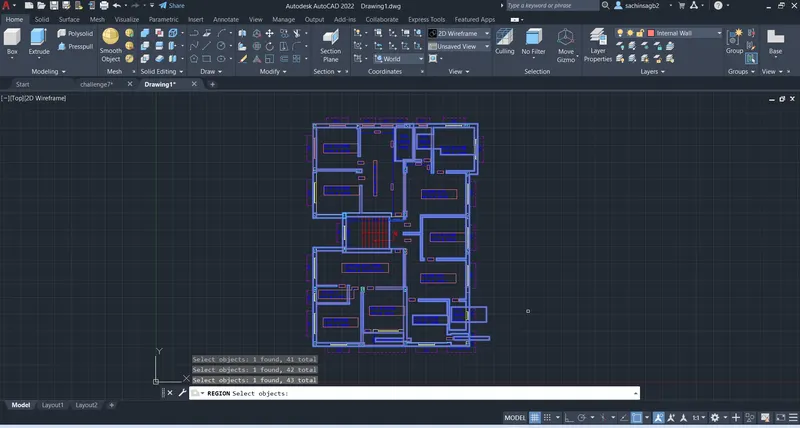 \
\
Now all wall paths Created as Regions
Now select all the Staircase steps and repeat the same procedure
Extrude: extrude the steps to 150mm
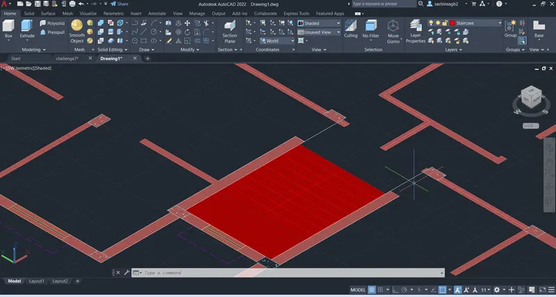
Move: select and move the steps one over the above
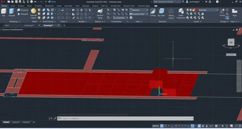
Now the Staircase Completed with steps
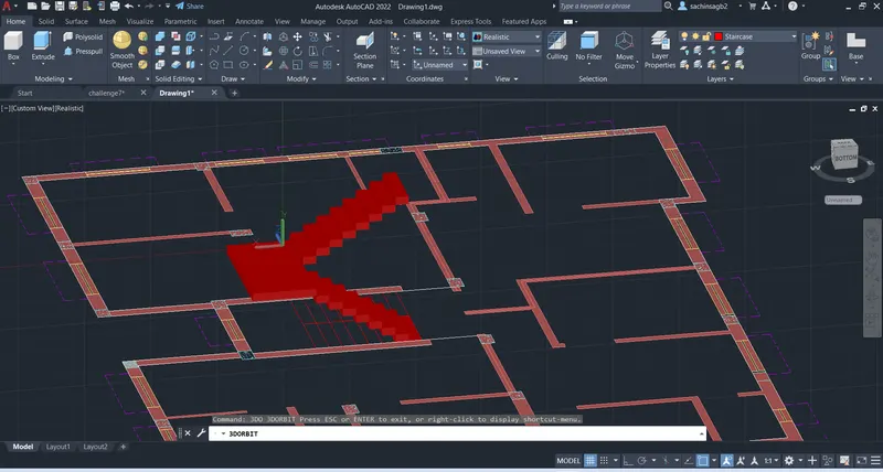
Circle : create the Circle with 100mm Diameter
Copy : select and copy the circle and place it over all the steps
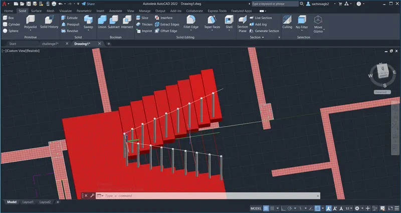
Extrude : Select and extrude the circle 100mm to create the balusters
Line: Create a line over all the railings to connect the all the Balusters over the top
Circle : Create the circle of Diameter 50mm
Sweep : Specify the sweep as the Line and object as Circle to create the Railing
Extrude: Select wall region and extrude it to the Height of 2450mm
Erase : Select all walls over window region and erase it
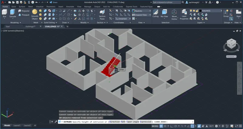
Select the Window region and Copy and Paste it to the height of 1m and 2.1m to create the opening for window frame
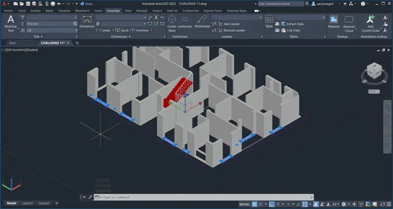
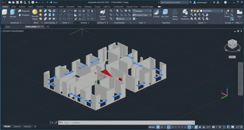
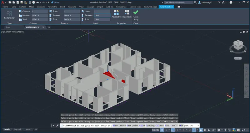
Extrude : select and Extrude the window sill wall
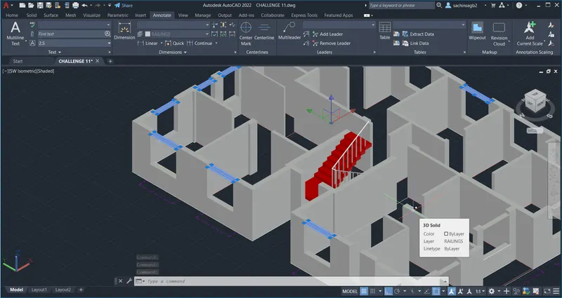
Extrude the the object and crete Lintels
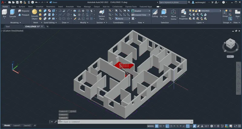
UCS : select ther FACE option and place it on the wall face
Rectangle: Create the Rectagles and Offset to the size of Projection thickness
Region: Select the Rectrangle and create the Regions
Subtract: Select the total region and subtract the inner region
Extrude: select amd extrude the projection thickness to 100mm
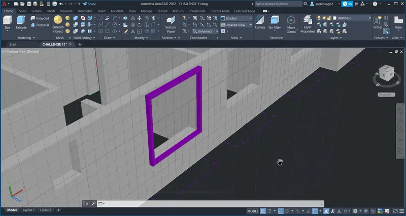
Copy: Copy and paste the projection to all windows
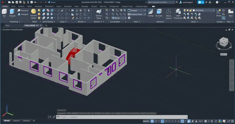
Now Create the Window frame
Material Browser : apply the materials such as wood, glass, Color etc,.
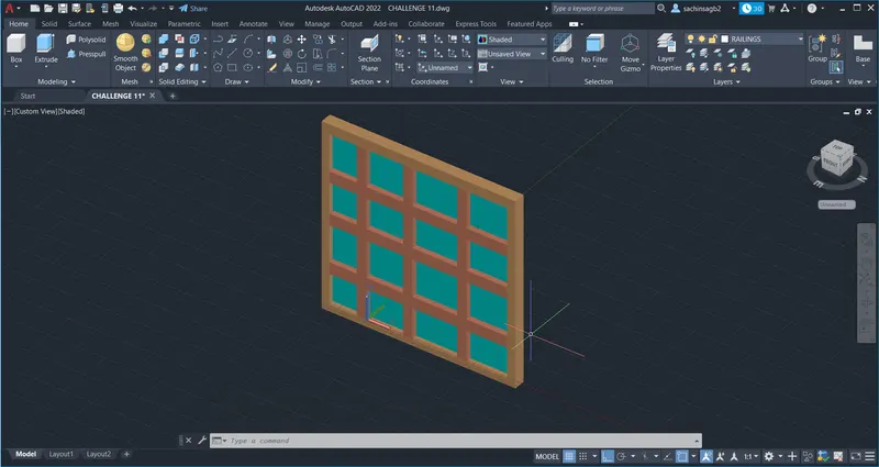
Select and place window to all the window openings
apply paint and to the walls and floorings from the material browser
Polyline :Create the line around the Plan and create as region from boundary option and Create the thickness as 450mm tocreate the Foundation
select the same polyline and place it over the wall and Extrude it to the Thickness of 125mm to Create the slab
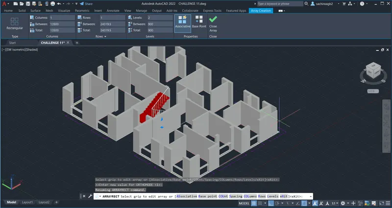
ARRAY: Select the entire model excluding the foundation, set the column and row as 1 and Level as 2, in between 2575mm
to create the 2 storeys
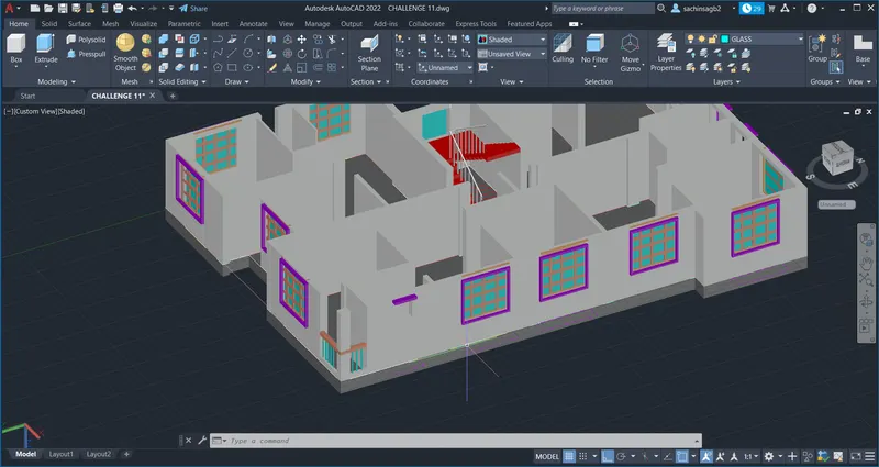
Rectangle : Create the multiple Rectangle to create the penthouse plan
Offset: offset it to the wall thickness
Extude: Extrude the walls upto 3m and Create the Roof using Sweep otion by creating sweep object and sweep path
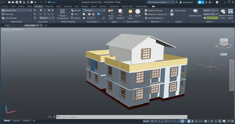
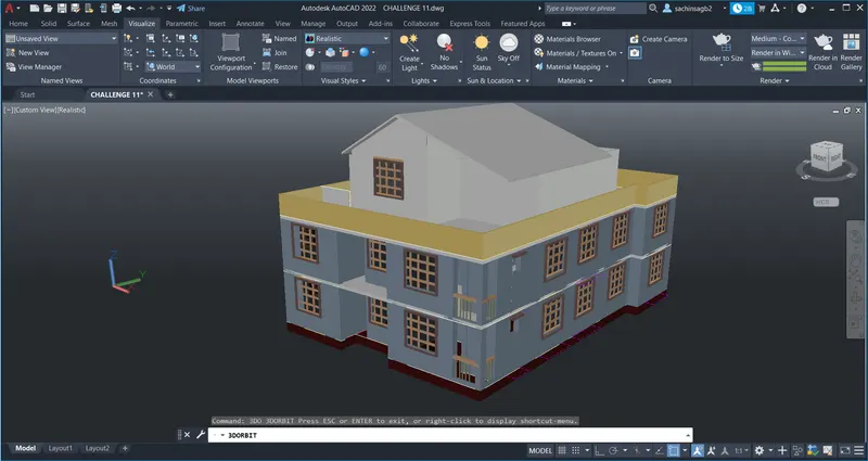
VISUALIZATION: Create the Light and Sunstatus as per the Requiements
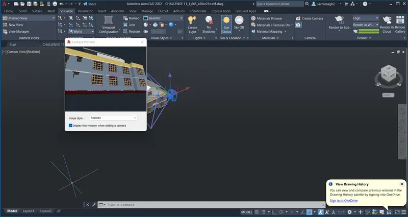
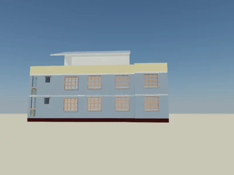
Set the Camera and its angle on Desired Position Get the Diffrent rendered View
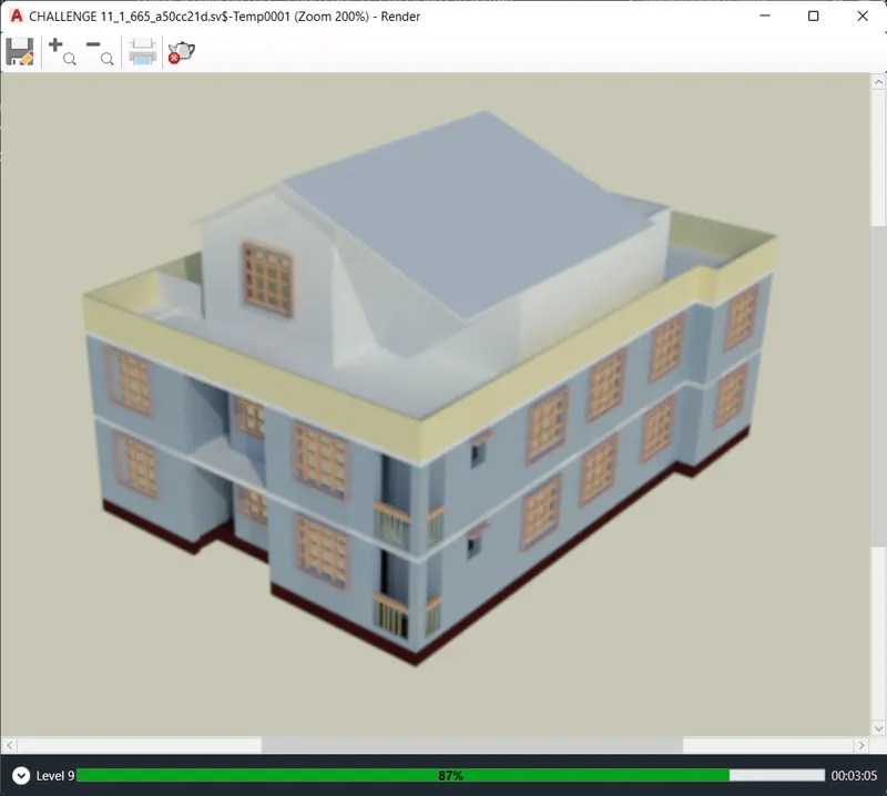
RENDER: Set the quality as per the requirement and Click on RENDER to Get the Rendered view of the 3Dmodel
RESULT: