Creation of geometries by Coordinate system methods using AutoCad
ANSWERS :
AIM : To Draw the Geometries by Using Line tool from Auto Cad
PROCEDURE :
Step 1:- Firstly we need to CREATE a NEW file using QNEW, New
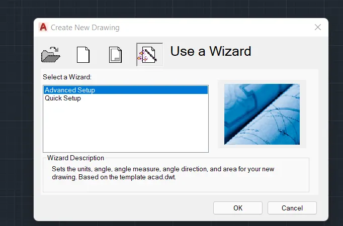
Step 2:- Setup the drawing platform using SETUP - STARTUP[1]-Set the units,templates, decimals, angle
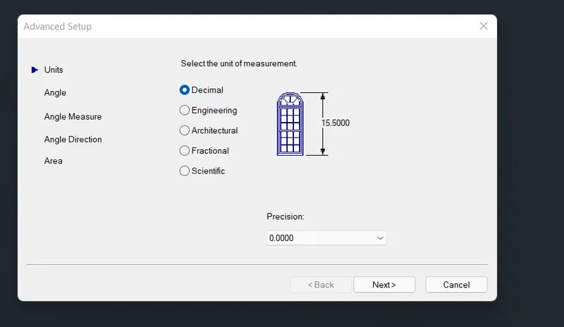
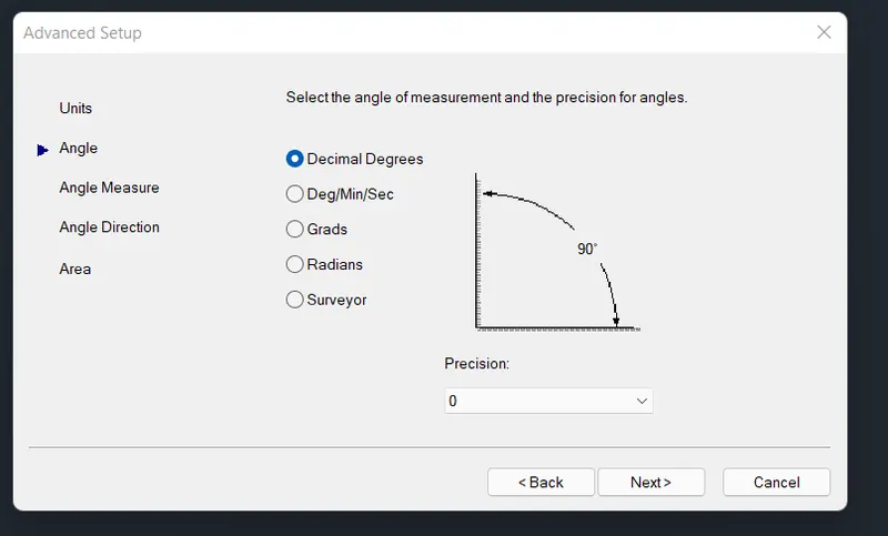
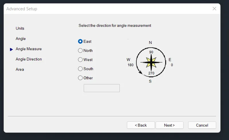
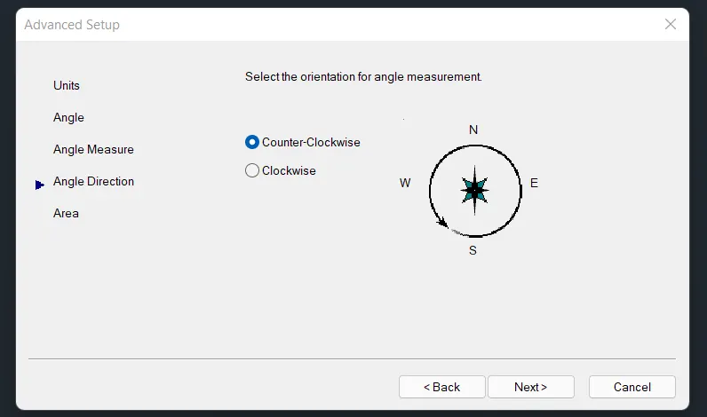
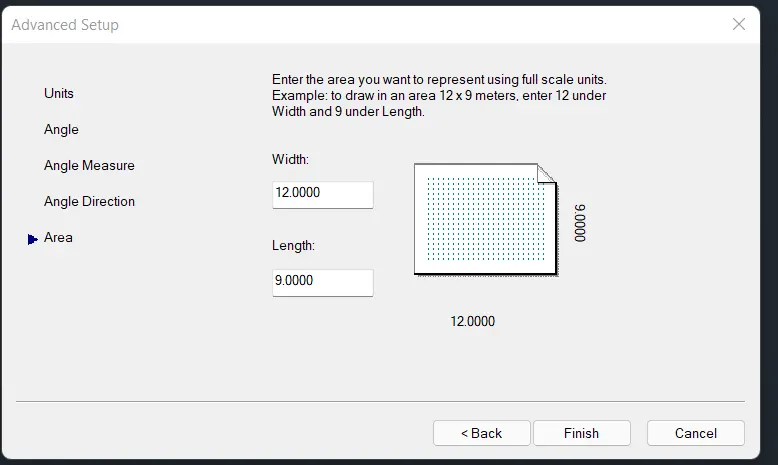
Step 3:- Now Select The Line Tool, from Menu Bar or Ribbon or typing 'LINE' from Command
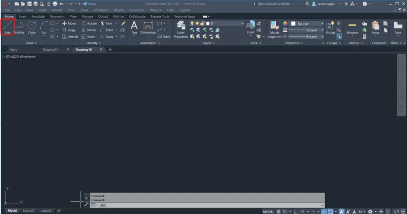
Step 4 :- we have 3 Cp-ordinate systems
a. Absolute Coardinate system
b. Relative Coardinate system
i) Relative Rectangular Coardinate system
ii) Relative Polar Coardinate system
c. Absolute Coardinate system
Step 5 :- As Metioned in the Drawing, SPECIFY THE FIRST of Line in command bar (as 0,0 , 1,2 ,0,2 etc.,)
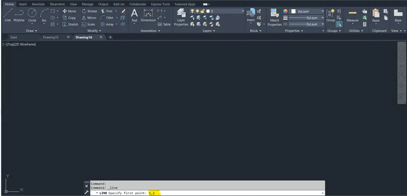
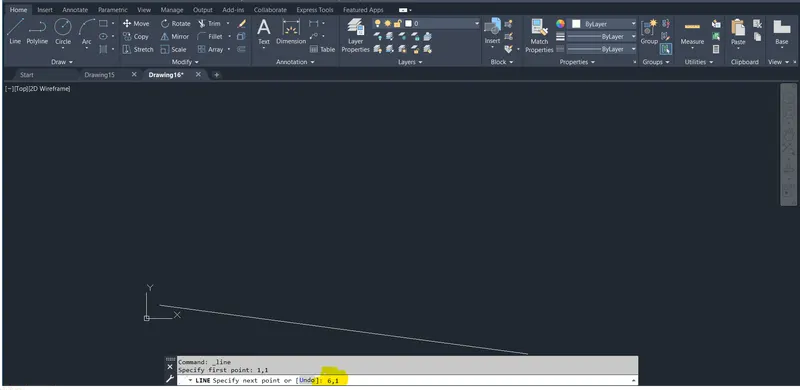
Step 6 :- SPECIFY THE NEXT Point by feeding Coordinates, For leniar pattern coordinates can be mentioned as 6,1
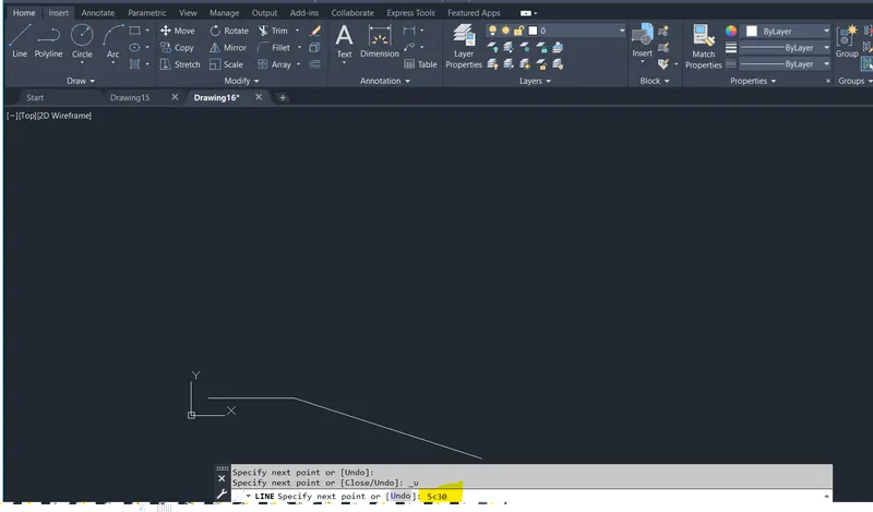
for angualar pattern SPECIFY as 5<30 Whereas 5 Indicates Length of the line and 30 indicates Measured angle from East direction. (Direction of measurements of angles can be modified as per requirement at )
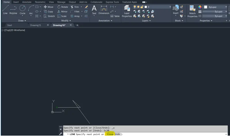
Step 7 :- Complete the Geometry by using CLOSE 'c' Command or by using Coardinate method
RESULT : All the Given GEOMETRIES are Drawn with help of Line tool in Auto Cad
all DWG FILES of Given Example are shared in this link https://drive.google.com/drive/folders/1PPPquR1ltc7XkpKHHQ_j8CP1leiJZixN?usp=sharing