Creating a Floor plan, Footing detail and Isometric view using AutoCad
ANSWERS :
AIM : To Draw the Geometries in Ortho and Isometric View with the aid of Line, Copy, Move, Offset, Trim, Extend tools in AutoCad
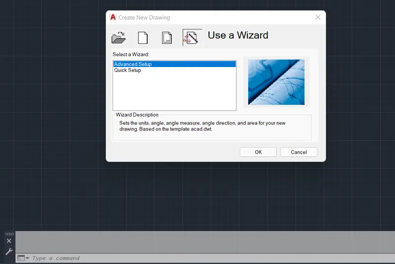
PROCEDURE : Open AutoCad and set the Units to Decimal system and Complete the setup.
1. CROSS SECTION OF LOAD BEARING WALL OVER SPREAD FOOTING
Select the Line tool and Specify the first point as 1,1 and Second Point as 0.9, 0
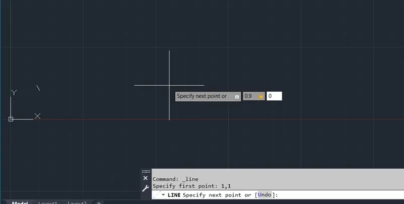
Specify the Next point as 0, 0.25
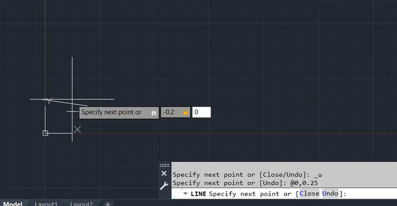
Specify the Next point as 0,0.4
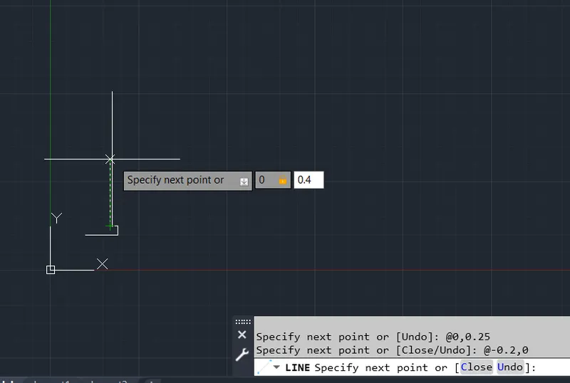
Specify the Next point as -0.05,0
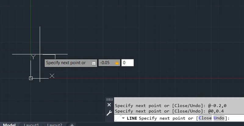
Specify the first point as 0,0.4
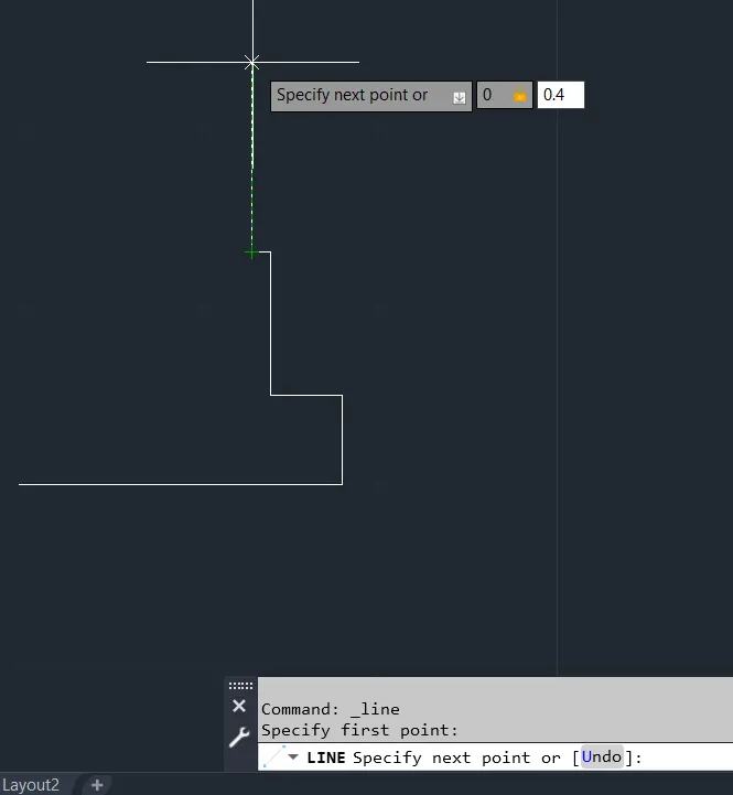
Specify the Next point as -0.05,0
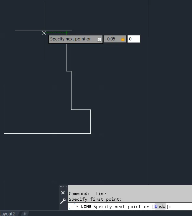
Specify the Next point as 0,0.6
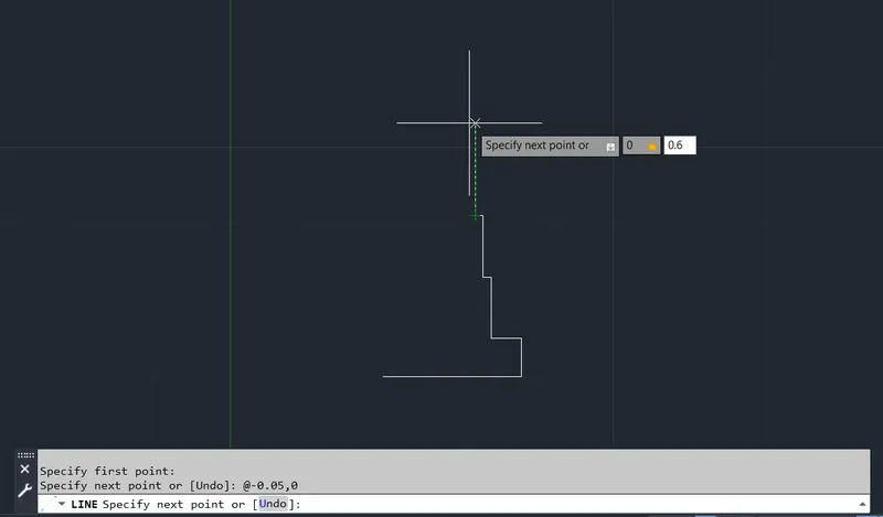
Specify the Next point as -0.3,0
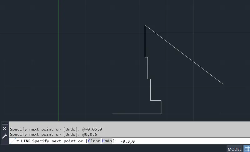
Specify the Next point as 0,-0.6
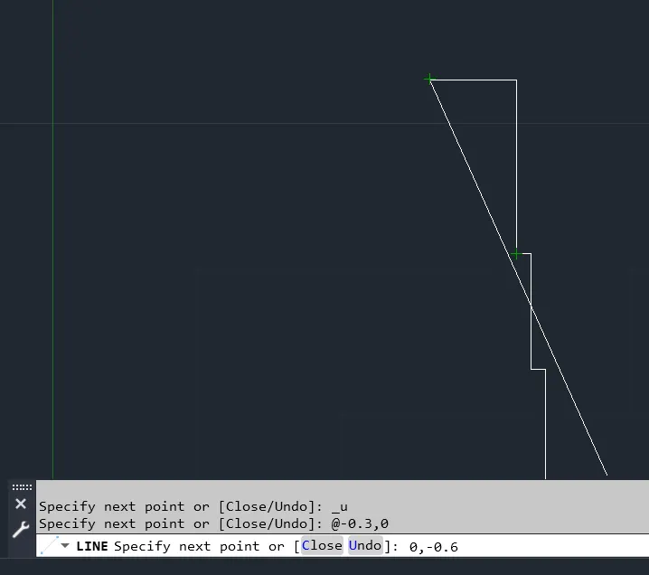
Specify the Next point as -0.05,0
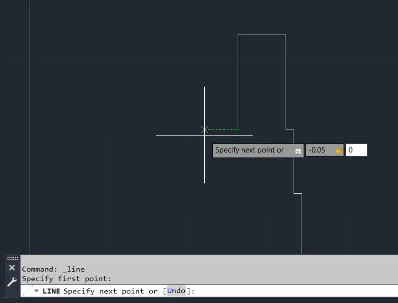
Specify the Next point as 0,-0.4
Specify the Next point as -0.05,0
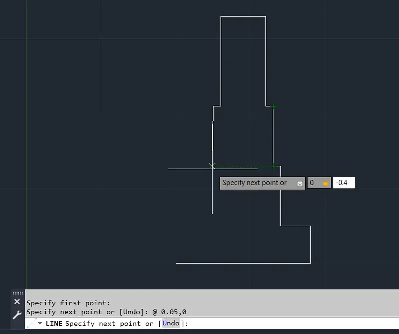
Specify the Next point as 0,-0.4
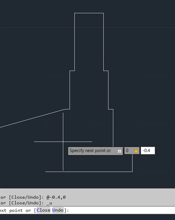
Specify the Next point as -0.2,0
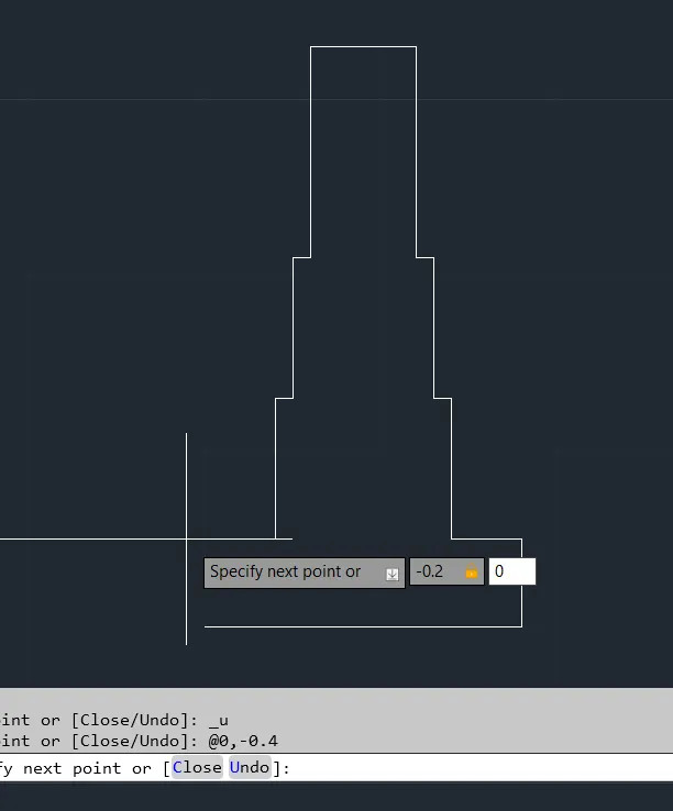
Specify the Next point at origin of first point and Close the Geometry
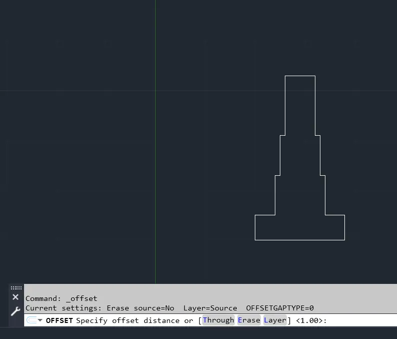
Select the OFFSET tool and Set offset the distance as 0.15 and Click outside the line
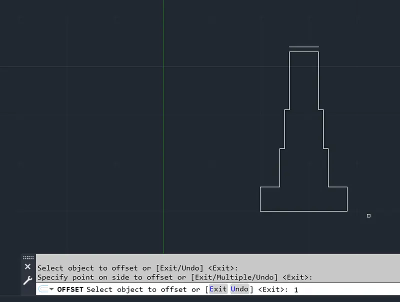
Select the OFFSET tool and Set offset the distance as 1 and Click outside the line
Select the Extend tool and Connect the offseted lines and Close the Geometry
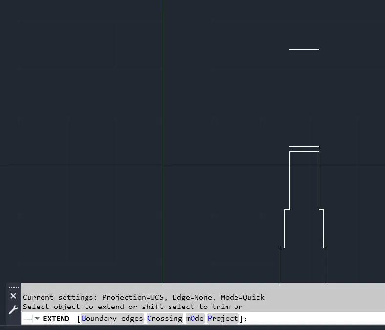
select Lin tool and Click on the left side of the Geometry and specify the distance as 0.15
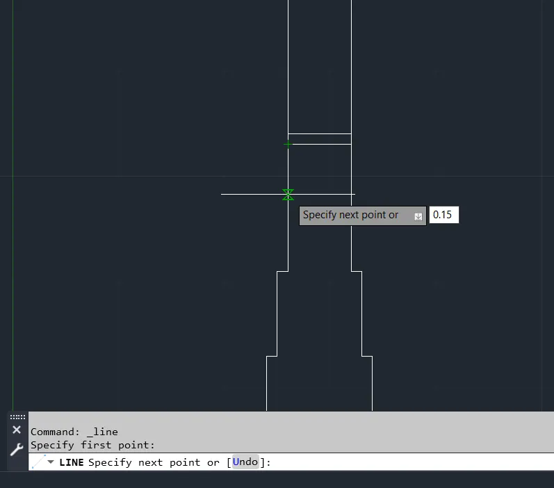
Specify Next Point as -0.3,0
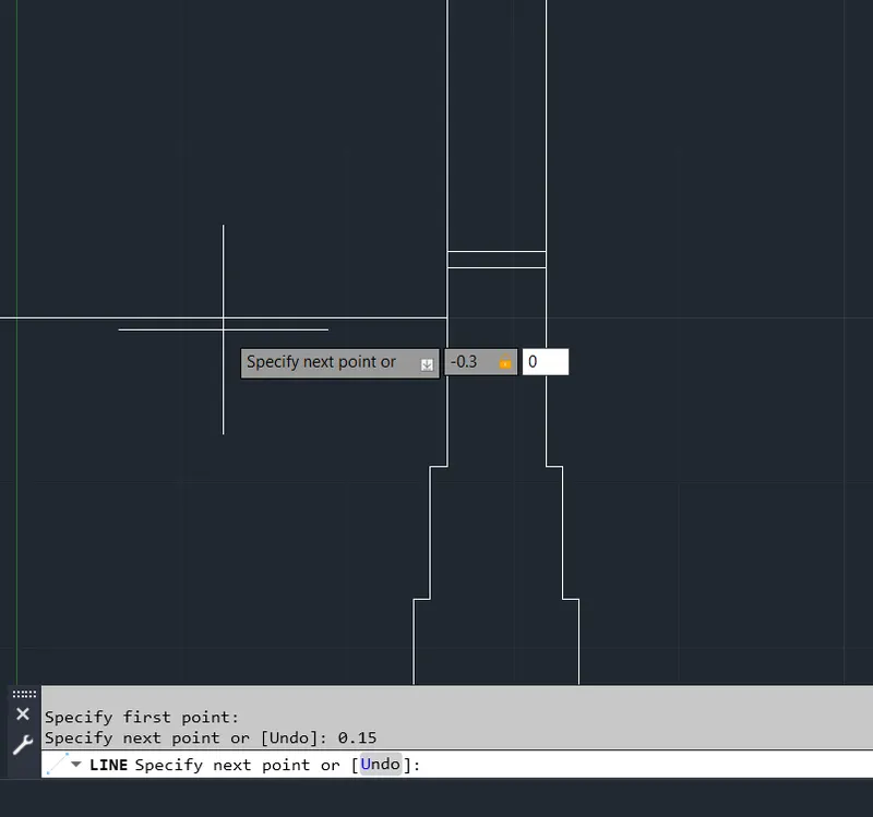
Specify Next Point as 0,-0.15
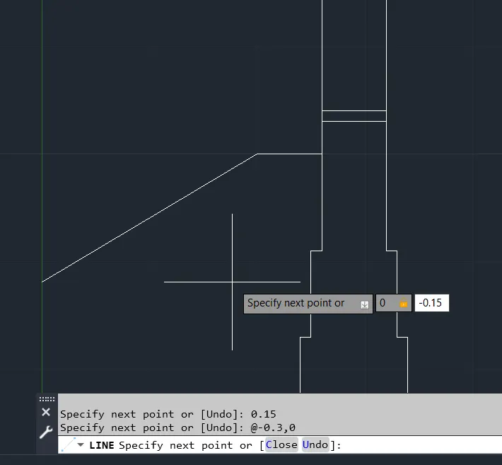
Specify Next Point as -0.3,0
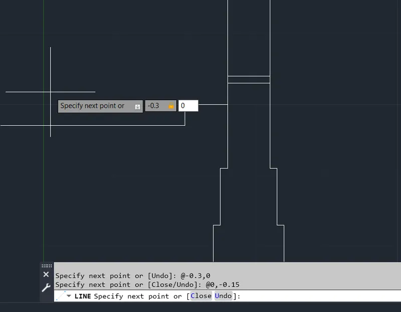
Specify Next Point as 0,-0.15
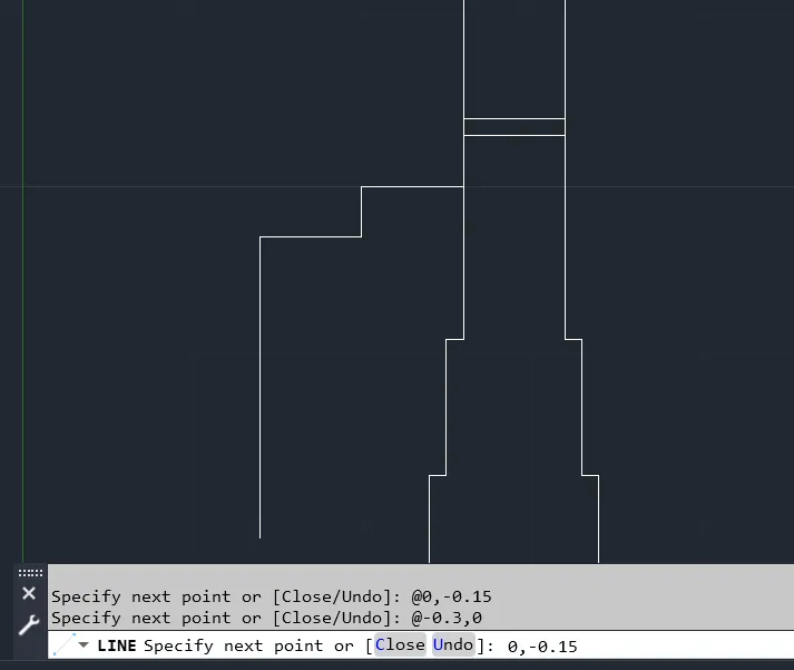
Specify Next Point as -0.3,0
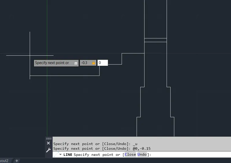
Specify Next Point as 0,-0.15
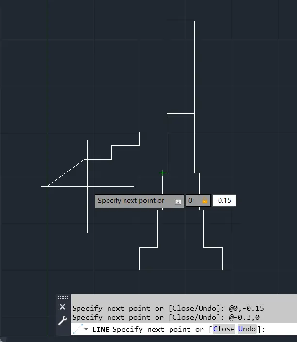
Specify Next Point as -0.3,0
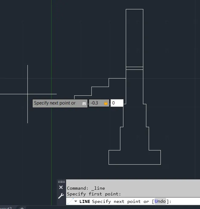
Specify Next Point as 1,0
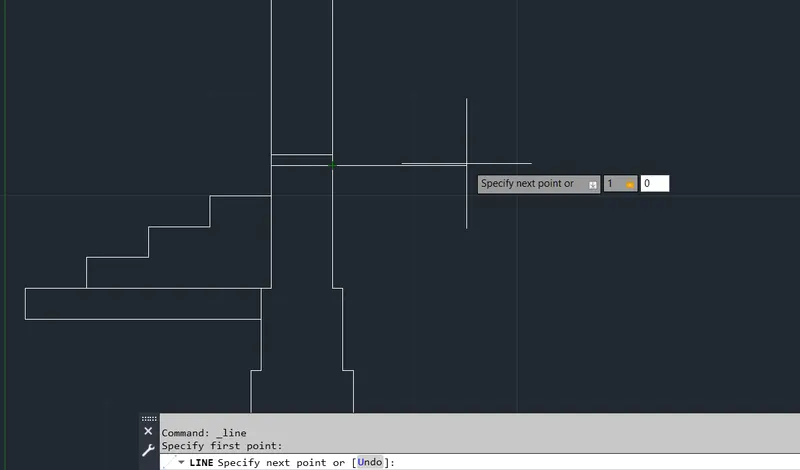
Specify Next Point as 0,-0.6
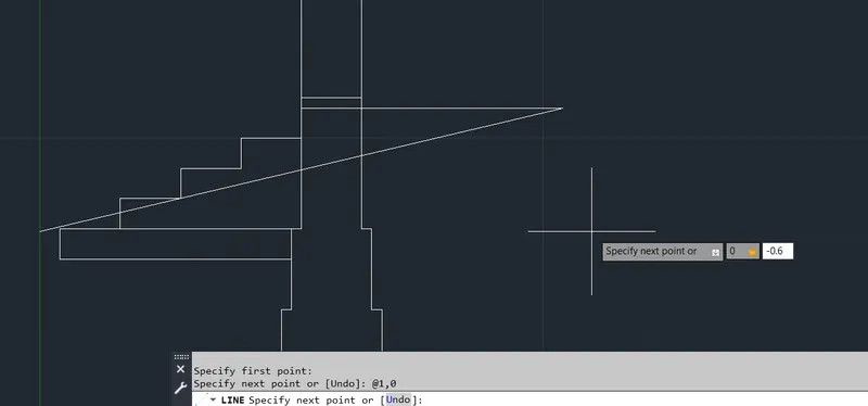
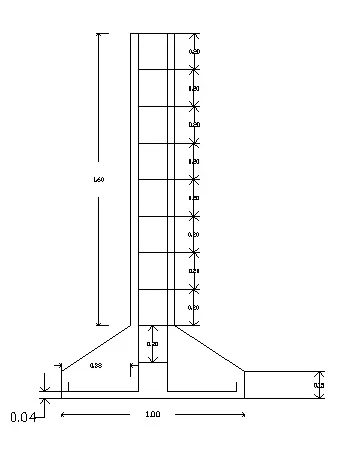
CROSS SECTION OF ISOLATED FOOTING
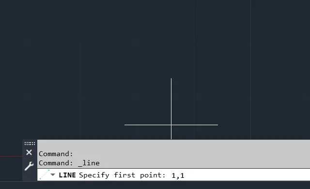
Select the Line Tool and Specify first Point as 1,1
Specify the Next Point as 1,0
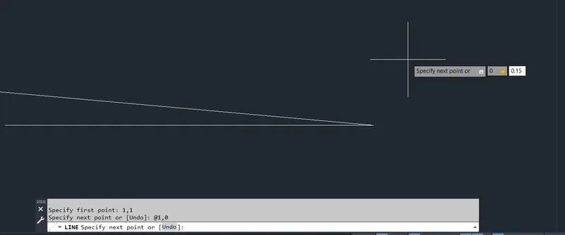
Specify the Next Point as 0,0.15
and Next Point as -0.38 , 0.25
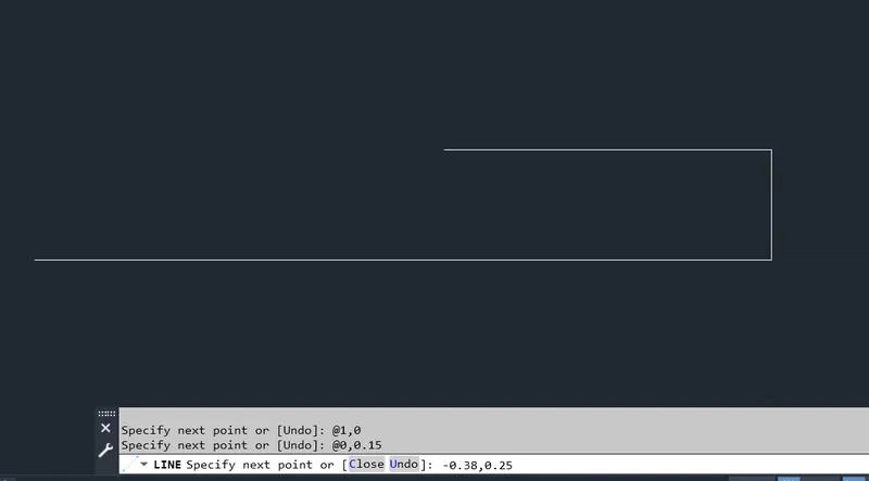
Specify the Next Point as 0,1.6
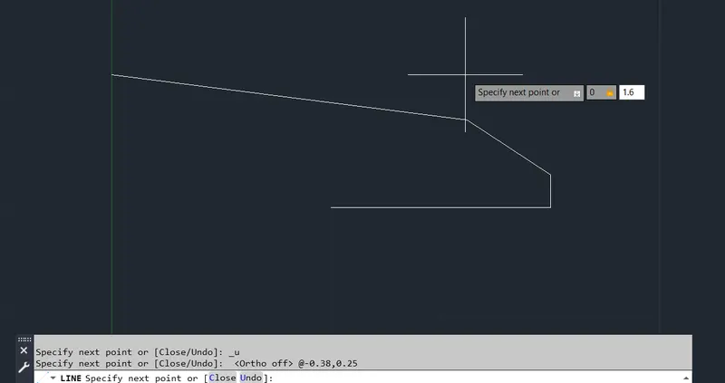
Specify the Next Point as -0.24,0
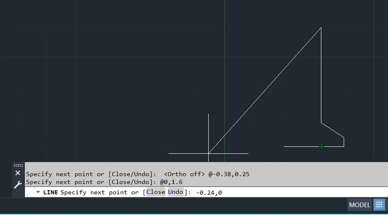
Specify the Next Point as 0,-1.6
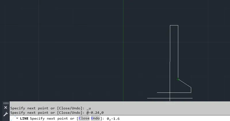
Specify the next point as -0.38,-0.25
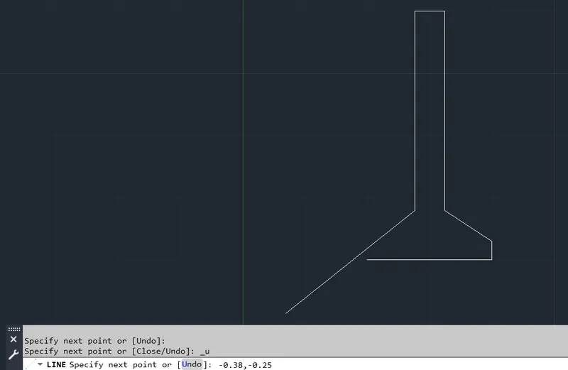
Specify the Next Point as 1.04, 1.09
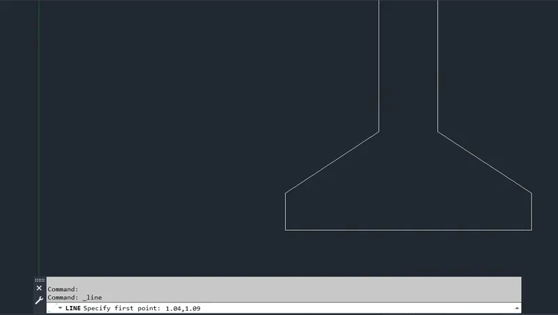
Specify the Next Point as 0, -0.05
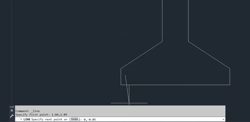
Specify the Next Point as 0.38,0
Now Connect the line to upper end of the Geometry,
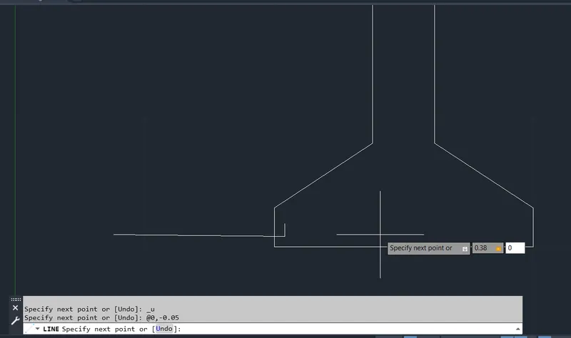
Select The Copy tool select the Highlighted Geometry select the corner as base point
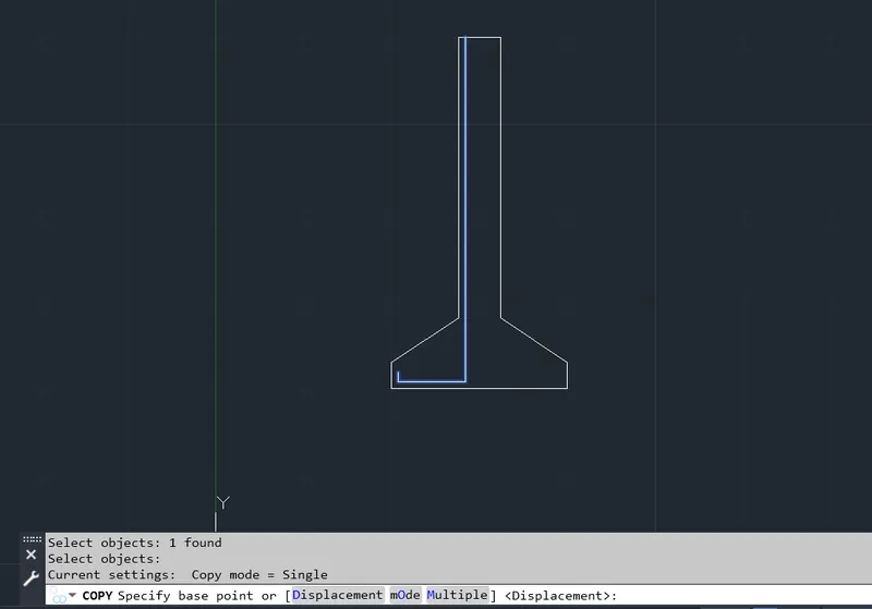
Select the Corner as Shown in the figure select Displacement and enter 1.58,1.04
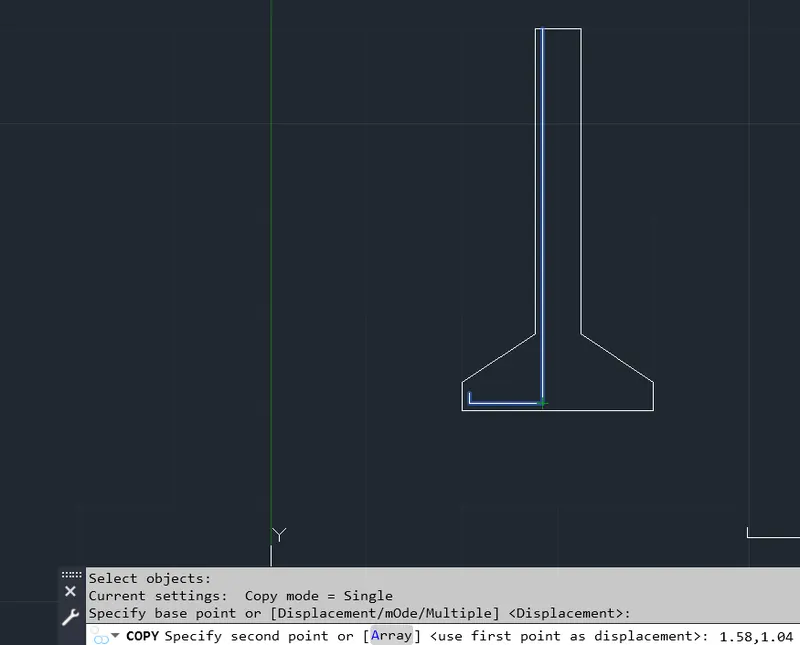
Now Select the Mirror tool and specify top and bottom end as first and second point and Mirror it
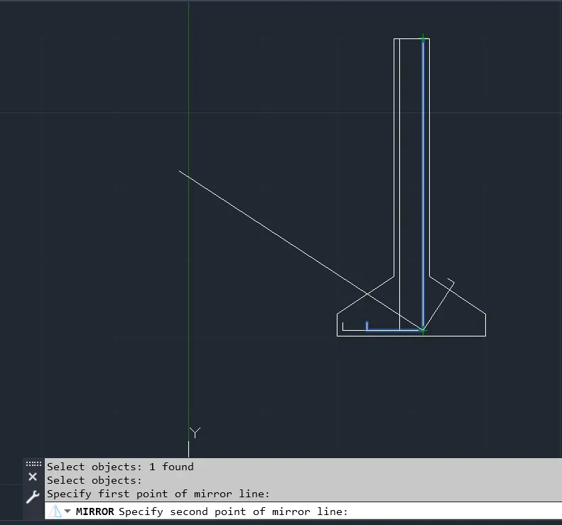
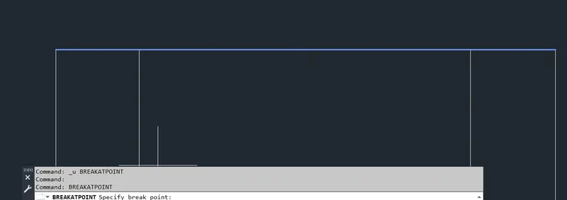
Now Select BREAKATPOINT tool and Split the line at every intersection
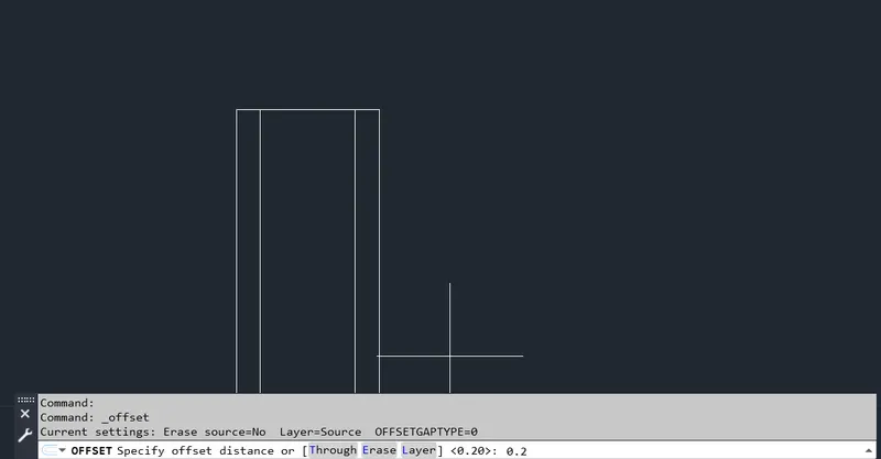
Now Select OFFSET tool and click on Center part and offset at every 0.2 intervals upto bottom
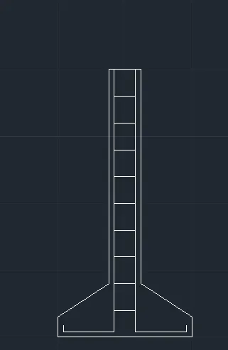
Now the CROSS SECTION OF ISOLATED FOOTING is done
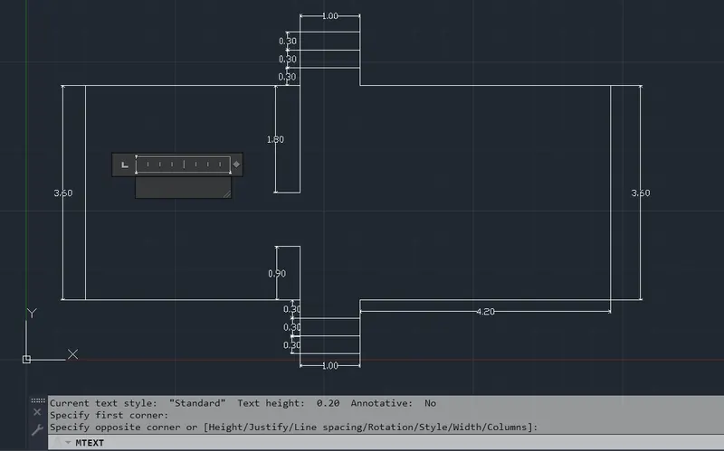
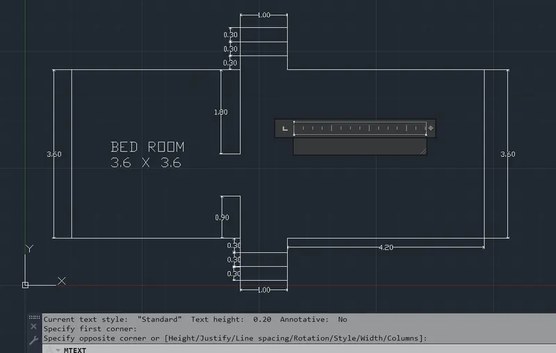
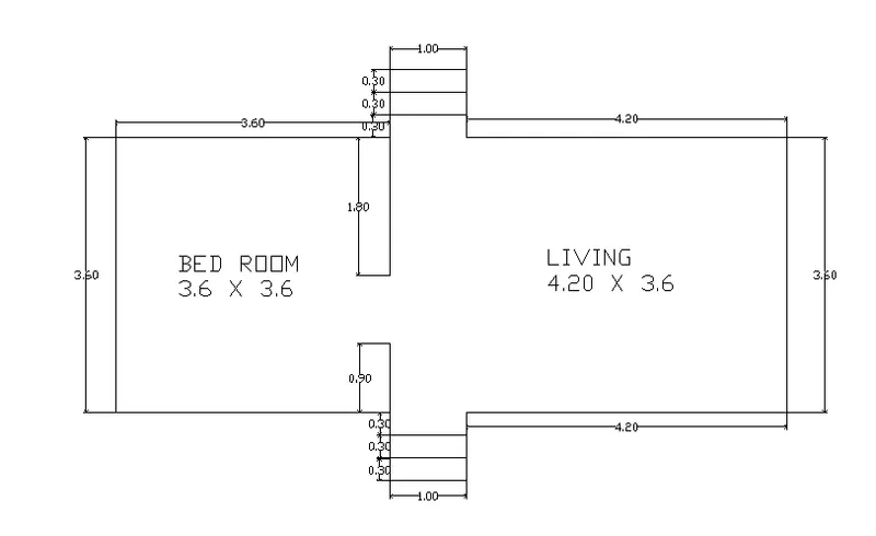
3. Line Diagram of Two Bedroom Building
Select the Line tool and Specify the First point as 1,1
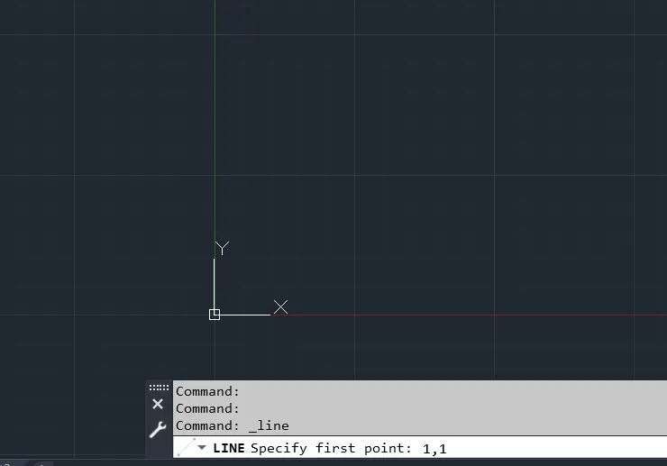
Specify the Next Point as 8.8, 0
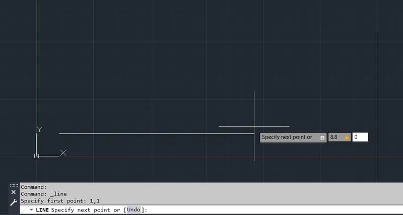
Specify the Next Point as 0, 3.6
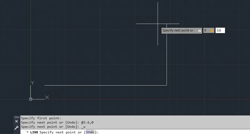
Specify the Next Point as -8.8, 0
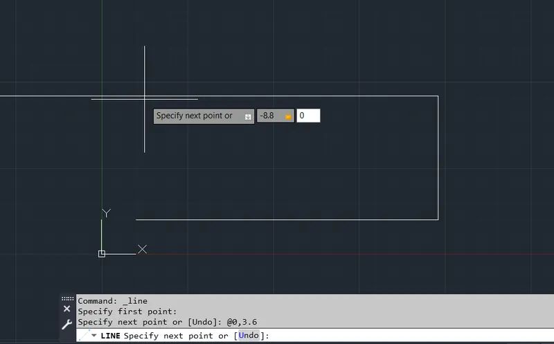
Specify the Next Point as Close the Rectangle by Clicking the next point of the line to the origin of rectangle
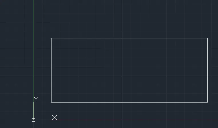
Select the OFFSET tool and specify the offset distance as 3.6
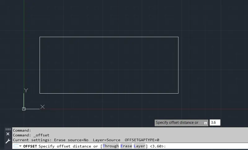
Click the first line and drag inside to create offset, To create the Steps, select the line tool ,
specify the First point at a distance of 3.6, Specify the next point as keep the direction in downward direction and specify as 0.9 or 0,-0.9
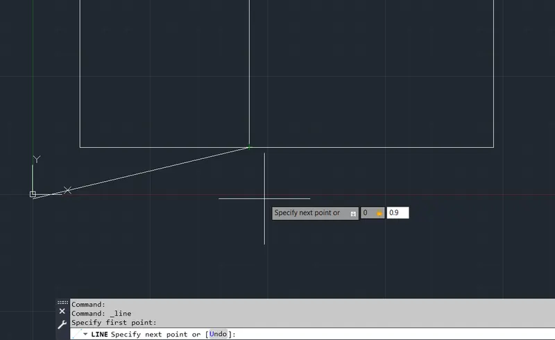
Specify the next point as 1,0 and Close the Line
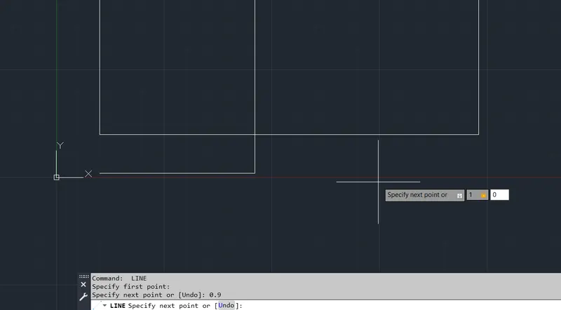
Select the Offset tool and Specify the offset distance as 0.3
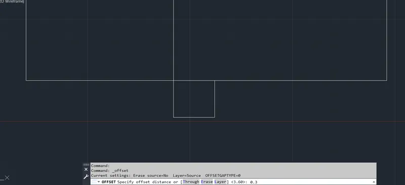
click on the line and make 2 offset lines
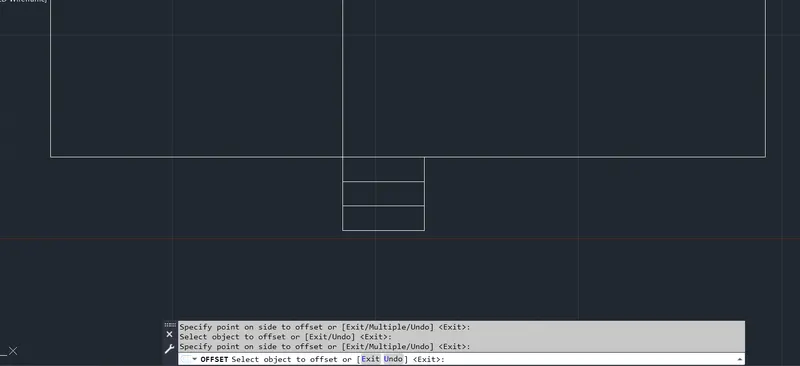
Similarly Create the Steps on Opposite side of the Rectangle
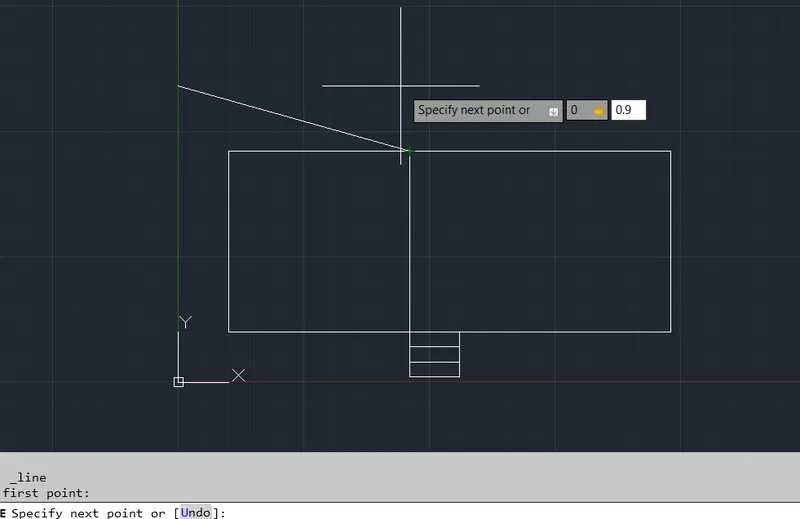
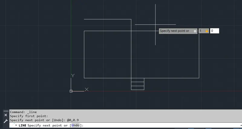
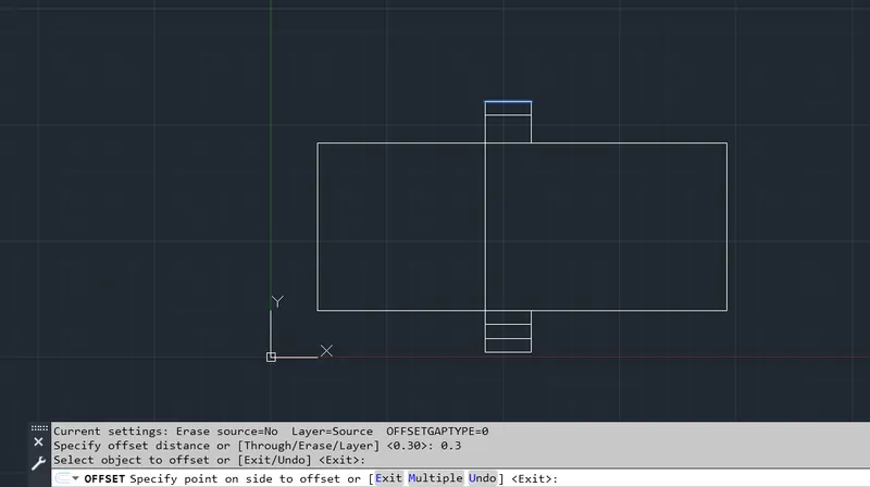
Now to Create the Opening we need to break the line at a distance of o.9 and 1.9
Select BREAKATPOINT Tool and Break the Line at a Distance of 0.9 & 1.9

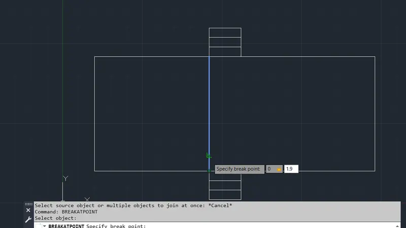
Select the Opening line and Delete it
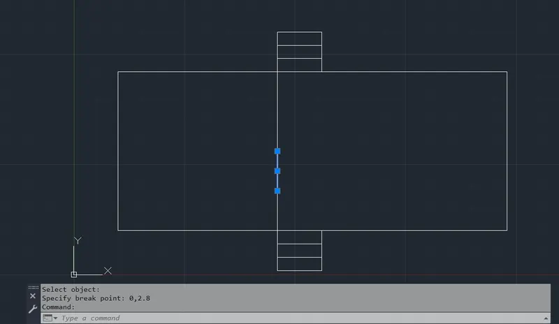
Now Door Opening is Created
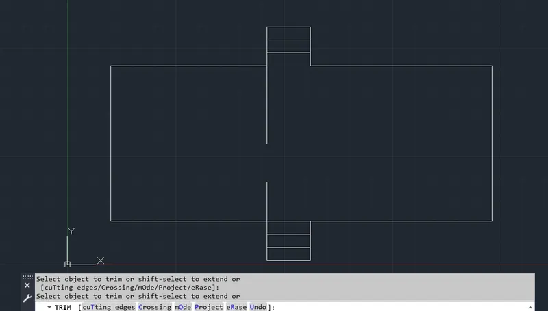
Check all the Dimensions and Select MTEXT and specify the room Designation and Dimensions
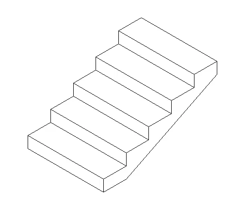
ISOMETRIC VIEW OF STEPS
To enable the Isometric view Select the Isodraft option Beside the Command bar and Click on left
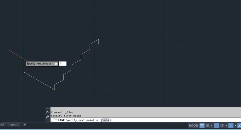
Select the Line tool and Specify the First point as 1,1
Specify the Next point as 0.15 in upper Direction and Specify the ISOPLANE RIGHT and Specify 0.3
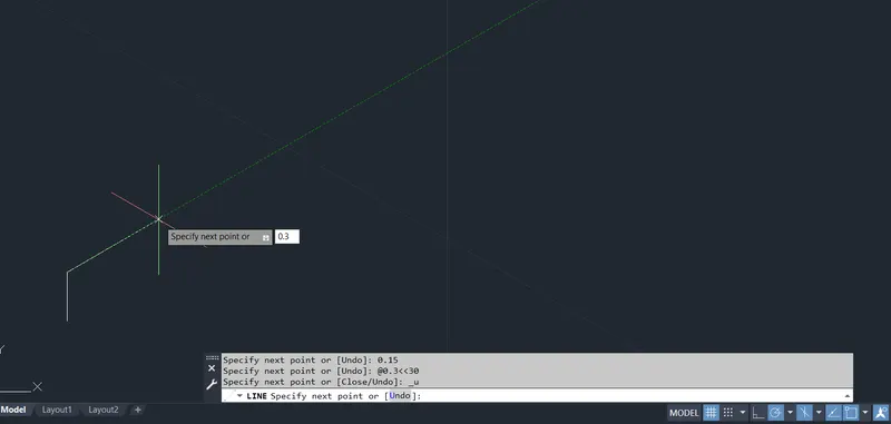
Similarly Create More Steps by same Procedure
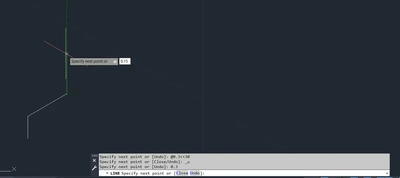
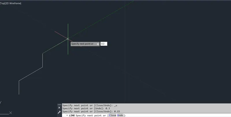
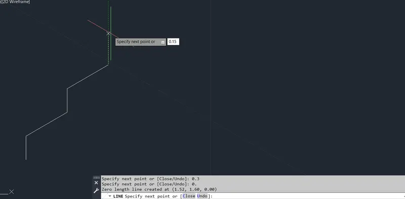
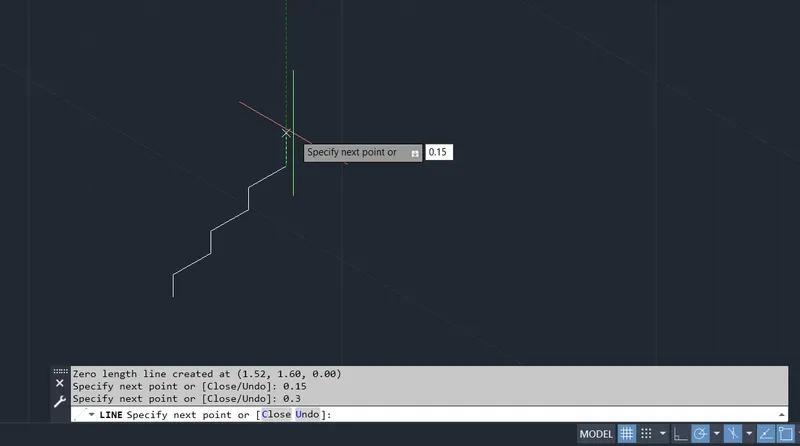
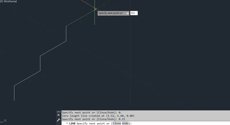
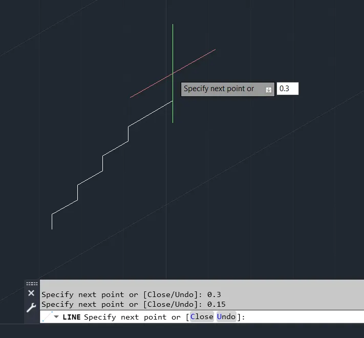
Now Drag the Line in Negative Y Direction and Specify 0.15
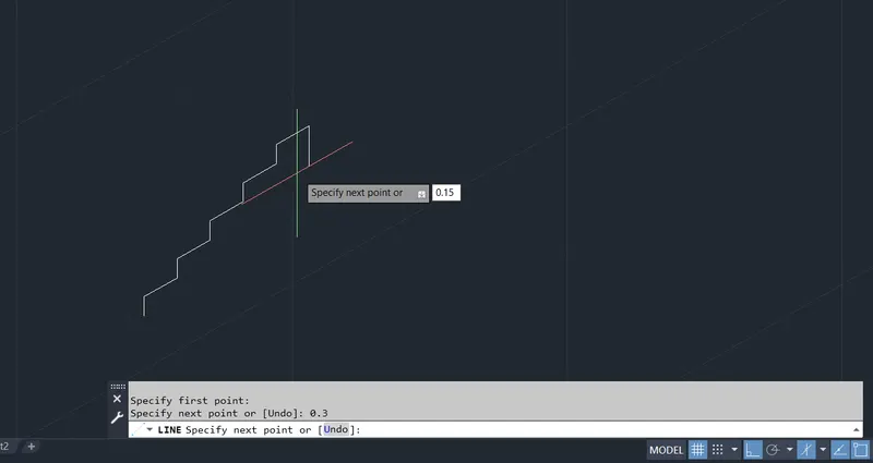
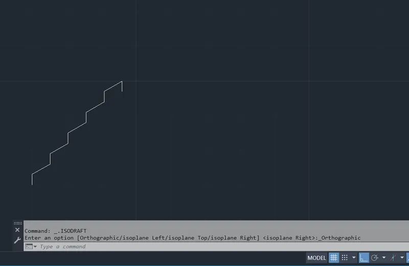
Now Click on the First Line and Specify as 1
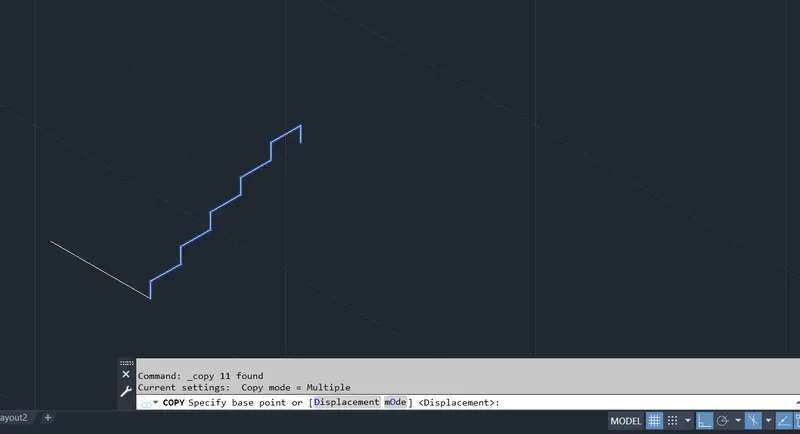
Now Select the Copy option and Select the First Line as Shown Below, and paste it at the next point of the line
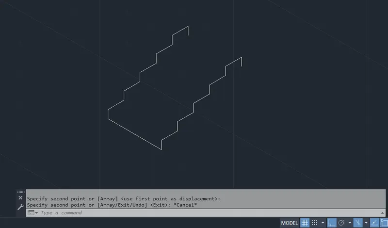
Now Create the Line between the steps with the help of Line tool
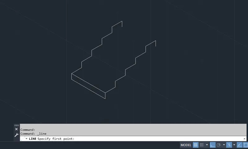
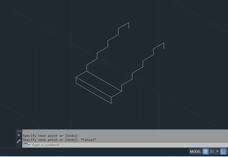
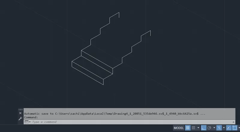
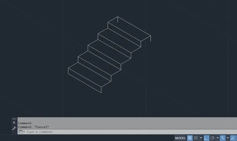
Trim the unwanted lines
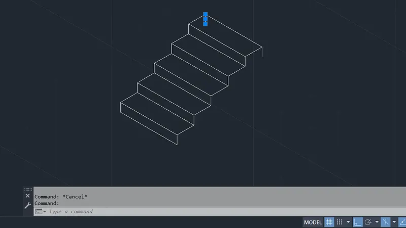
Select the Line tool and Specify the first point at first corner and next point as 0.3
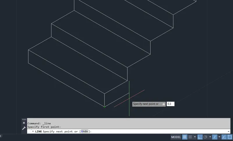
Connect the two points as shown in the figure
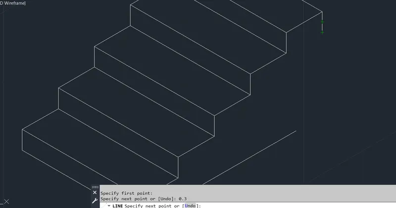
Steps is created with the isometric View
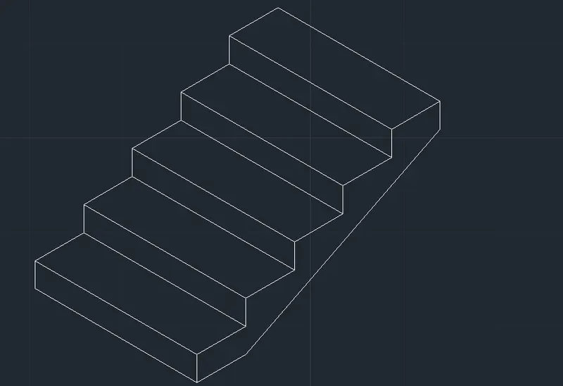
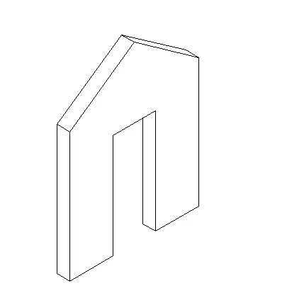
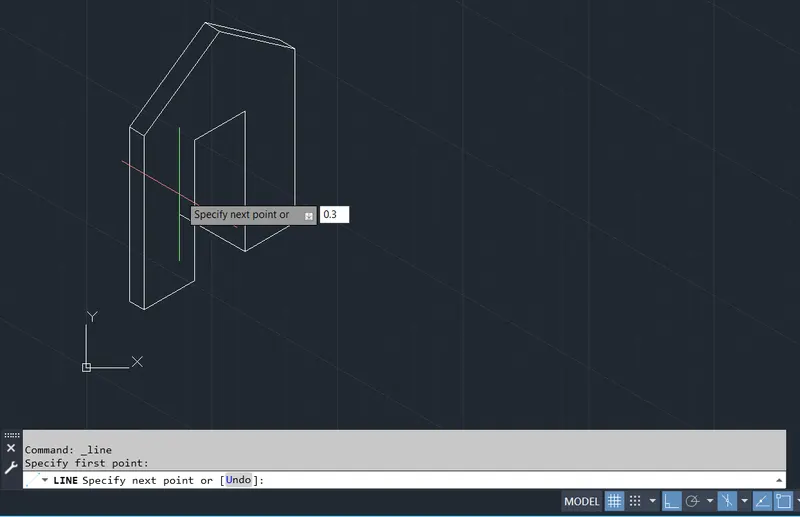
ISOMETRIC VIEW OF GABLE WALL
Select the Line tool and Specify the First point as 1,1 and Next point as 1 in ISO Right direction as shown in figure
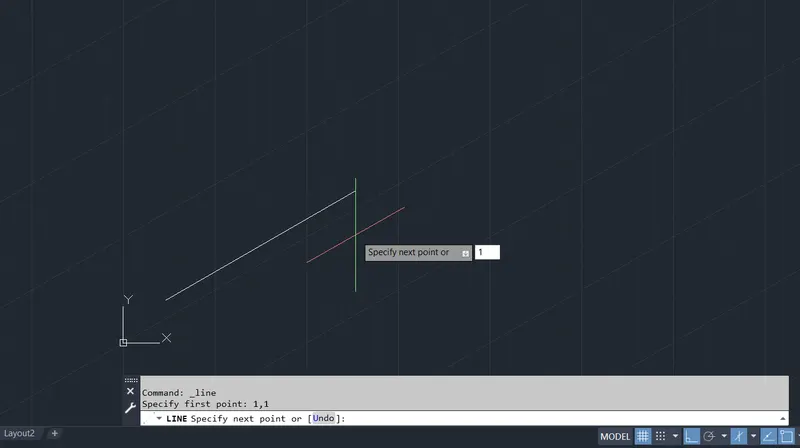
drag the Curser in upper direction and specify as 2.42
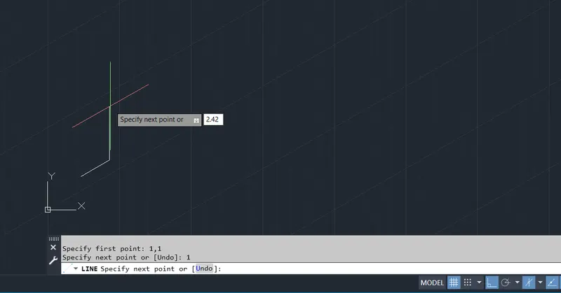
Specify the next point as 1 in Right direction
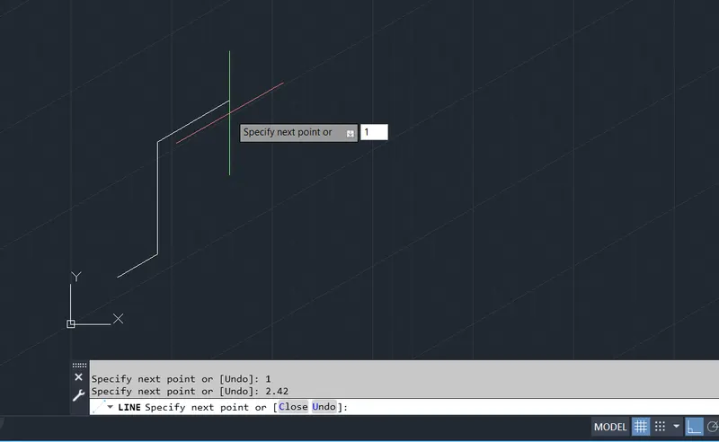
Drag the Curser in Downward direction and specify as 2.42
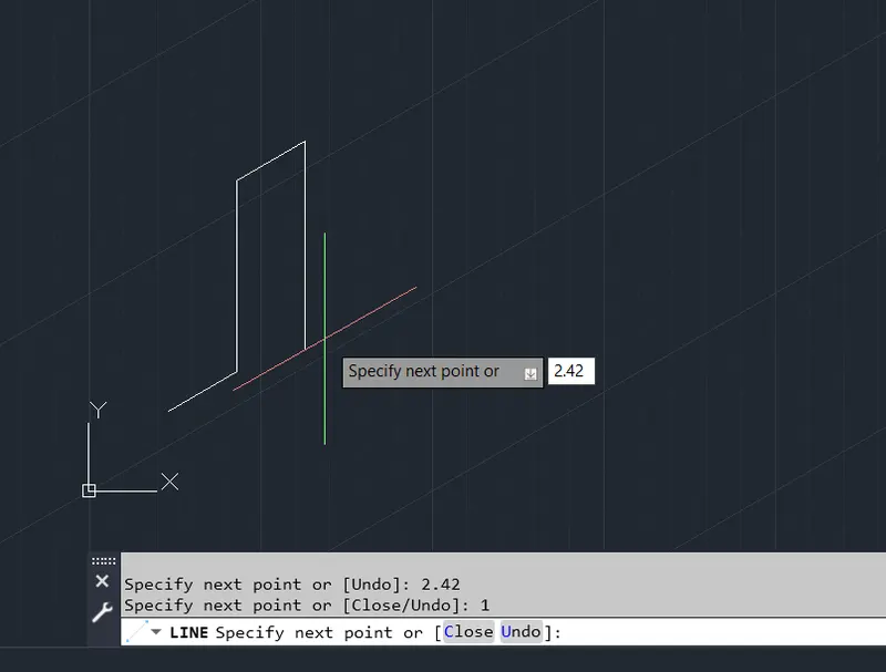
specify the next point as 1 in Right direction
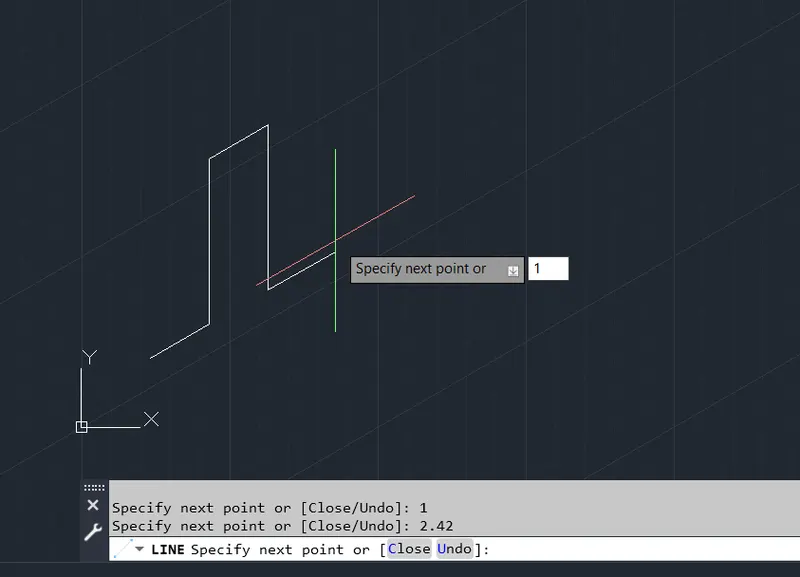
Specify the height as 3 in Both end upward direction and create the offset as 0.3
From the mid point of the Door at a distance of 1.63 create two lines connecting 2 ends as shown in figure
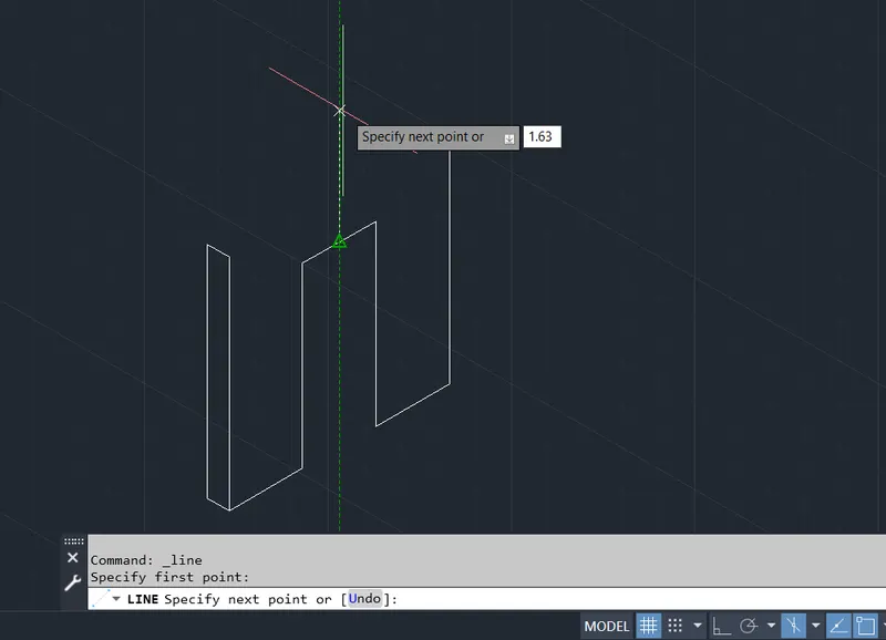
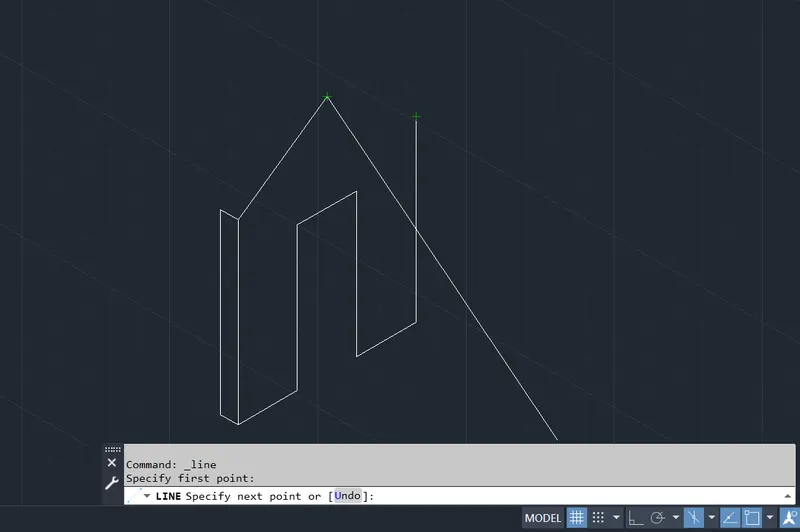
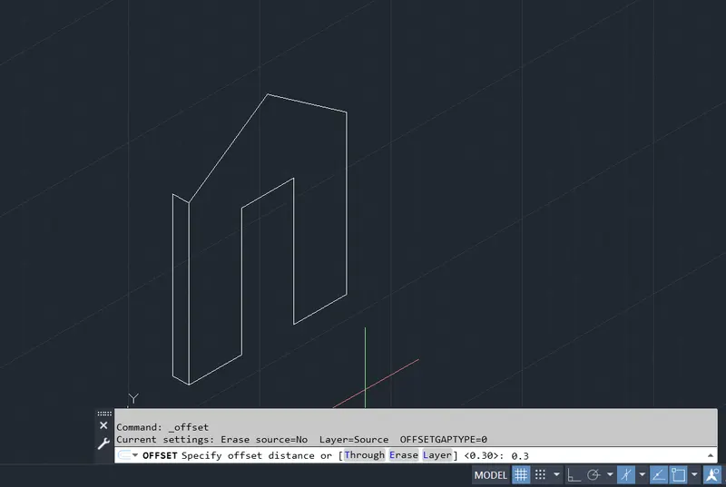
Select the Copy tool and Copy the lines as shown in figure
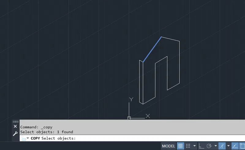
copy at other end as shown in the figure
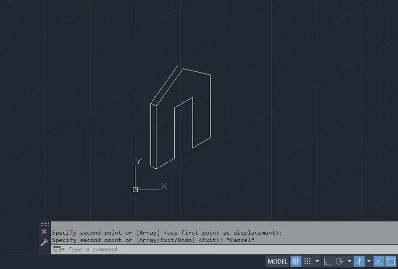
Similarly Copy the other line and paste it to the origin of the other line
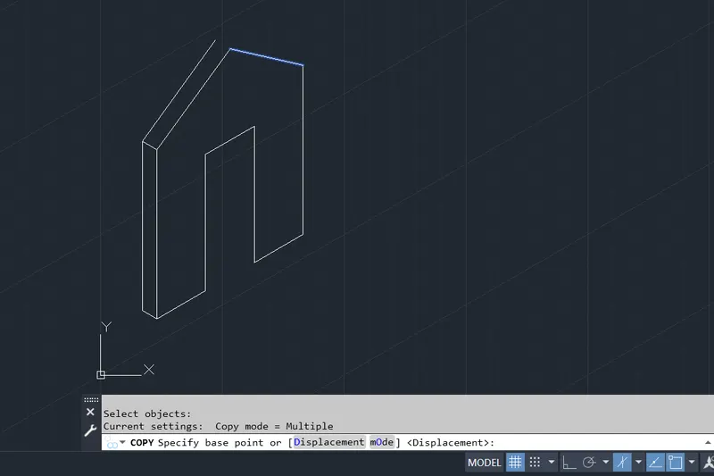 ]
]
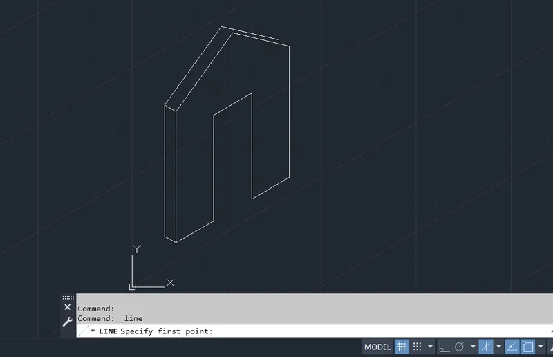
Connect the lines
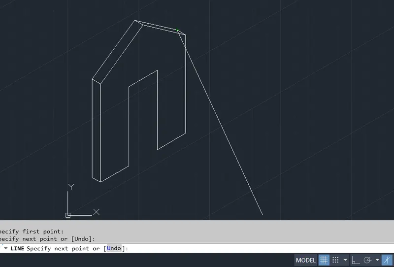
Now select the line tool and Click on the corner of the door and specify next point as 0.3 connect to the top
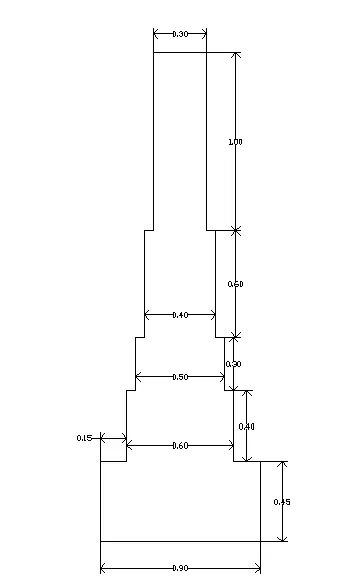
CROSS SECTION OF LOAD BEARING WALL SHOWING FOUNDATION DETAILS
Select the line tool and specify first point as 1,1 and next point as 0.9,0
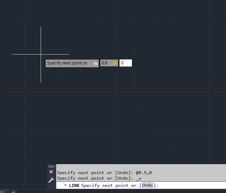
Specify the next point as 0,0.45
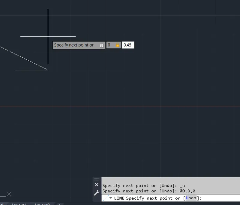
Specify the next point as -0.15,0
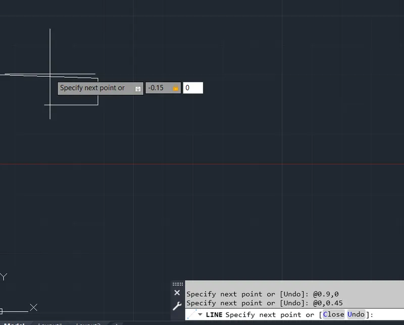
Specify the next point as -0.05,0
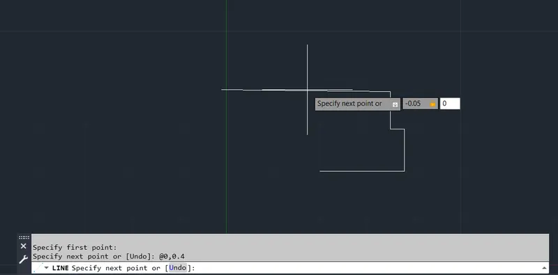
Specify the next point as 0,0.3
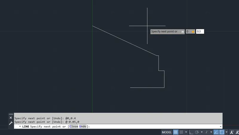
Specify the next point as -0.05,0
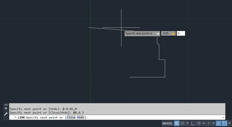
Specify the next point as 0,0.6
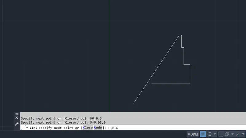
Specify the next point as -0.05,0
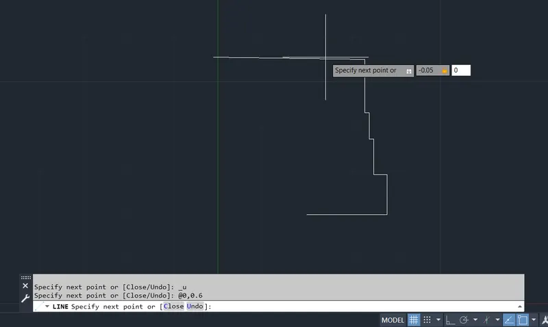
Specify the next point as 0,1
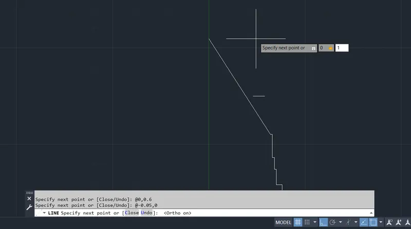
Specify the next point as -0.3,0
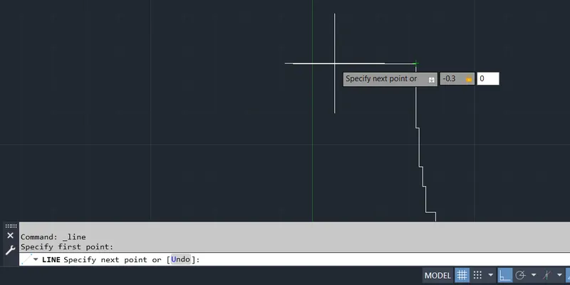
Specify the next point as 0,-1
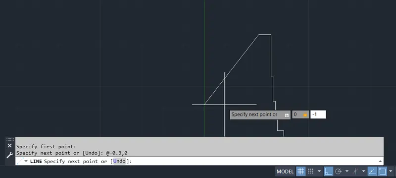
Specify the next point as -0.05,0
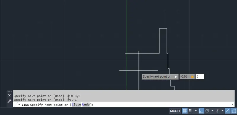
Specify the next point as 0,-0.6
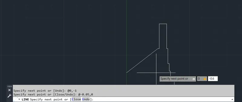
Specify the next point as -0.05,0
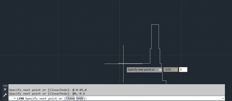
Specify the next point as 0, -0.3
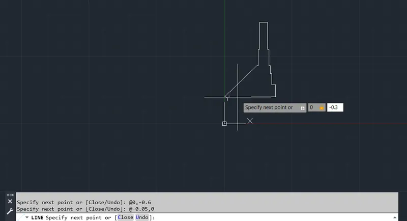
Specify the next point as 0,-0.4
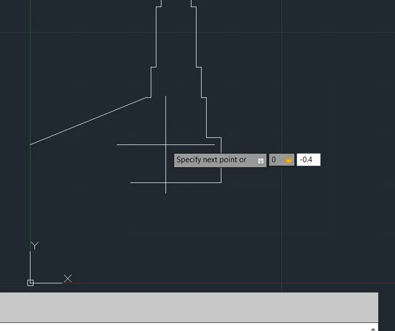
Specify the next point as -0.05,0 and next point as 0, -0.3
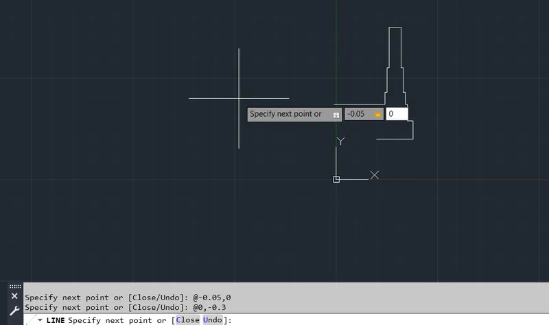
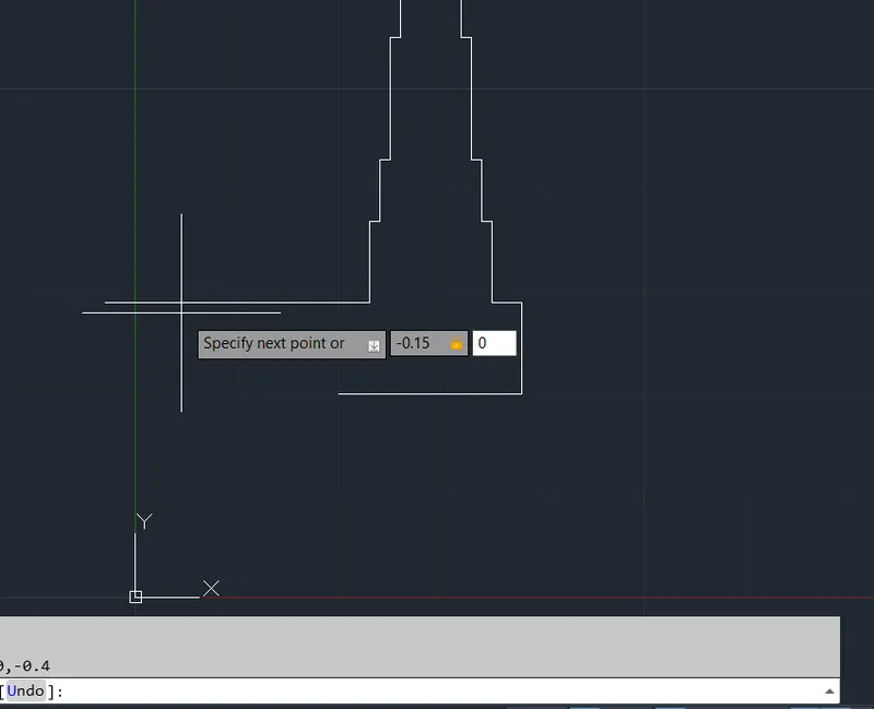
Specify the next point as -0.05,0 close the Geometry
RESULT
C/S OF THE LOAD BEARING WALL OVER SPREAD FOOTING
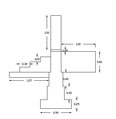
C/S OF THE LOAD BEARING WALL OVER SHOWING FOUNDATION DETAILS
C/S OF ISOLATED FOOTING
LINE DIAGRAM OF TWO BEDROOM BUILDING
ISOMETRIC VIEW OF STEPS
ISOMETRIC VIEW OF GABLE WALL