Drafting of various geometries using Chamfer, Fillet tool in AutoCad
ANSWERS :
AIM : To learn the Drafting of Various kinds of Geometries with the help of Chamfer, Fillet, tools in AutoCad
Procedure :
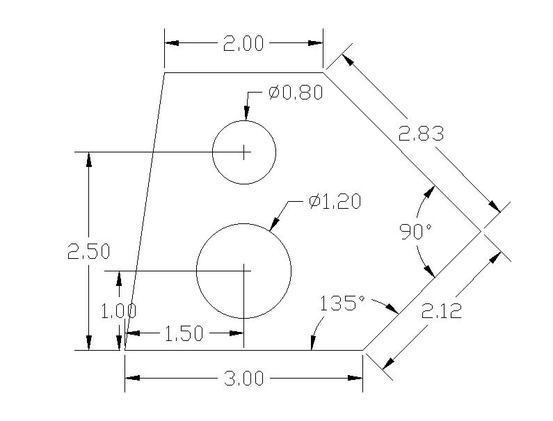
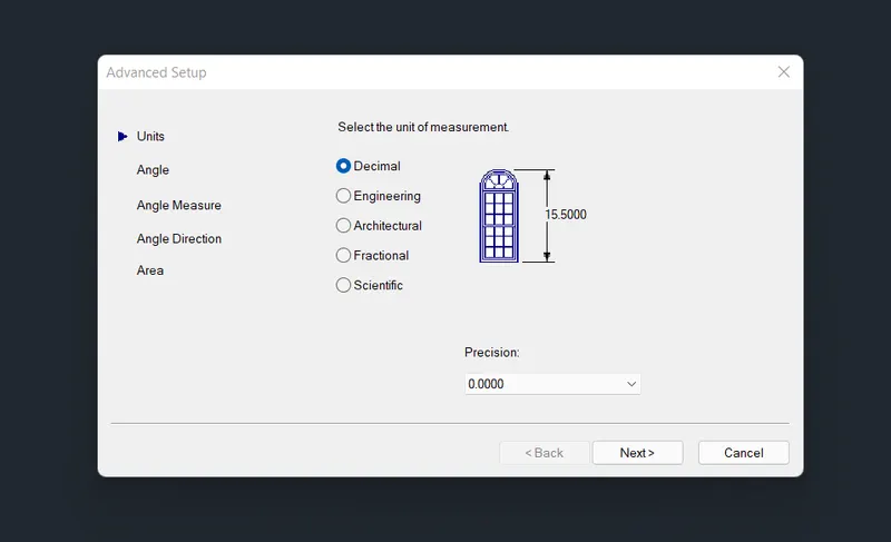
Geometry 1 - DECIMAL
Setup the Unit of Measurements to Decimal
Select Line tool or type L on command bar
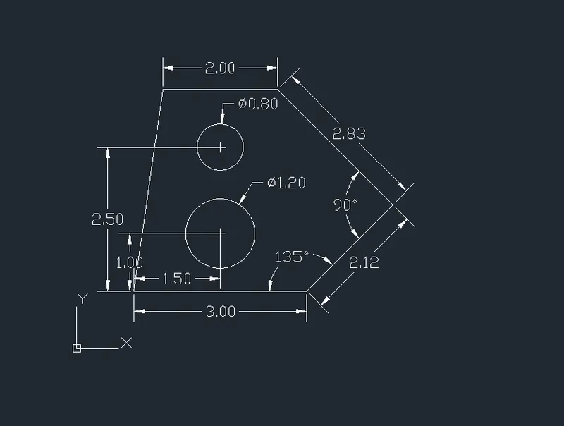
Specify First point of line as 1,1
Specify Second point of line as 3,0
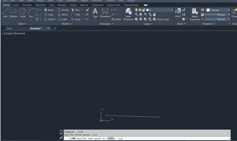
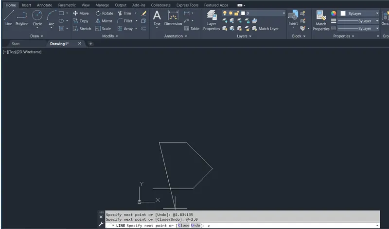
Specify Next Point as 2.12<45
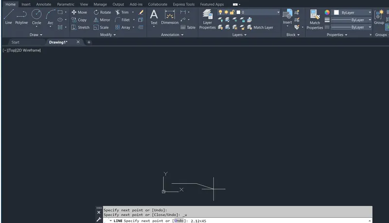
Specify Next Point as 2.83<135
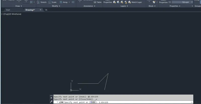
Specify Next Point as -2,0
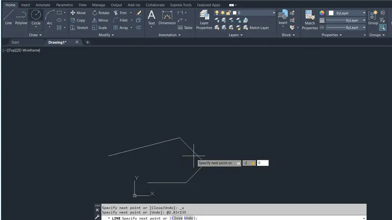
Close the Line by Selecting Close Option or Type C in command bar
Now Select CIRCLE Tool in ribbon or type CIRCLE in command bar and press Enter
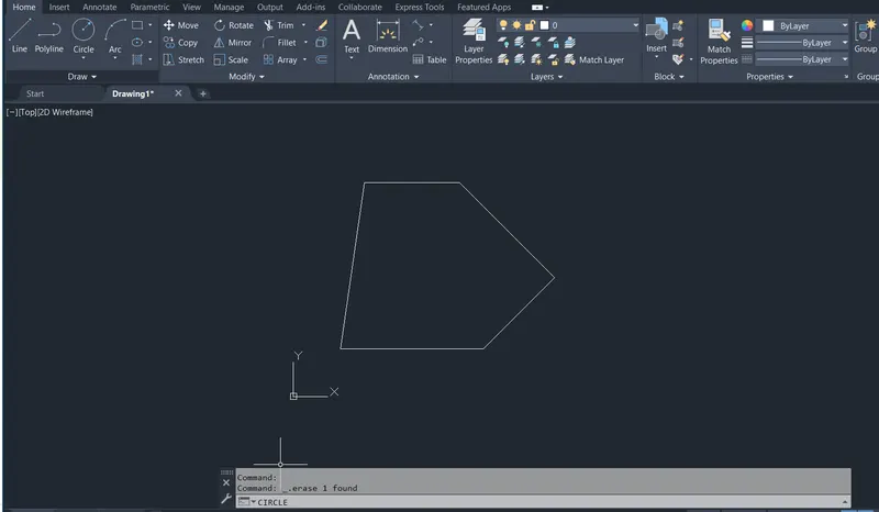
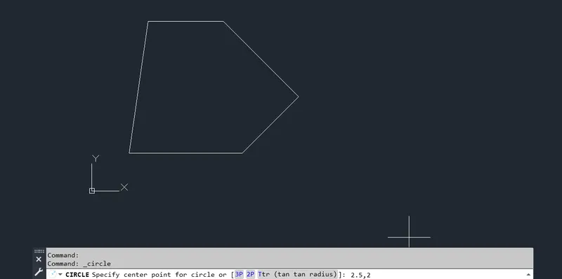
Specify The Center Point of the Circle as 2.5,2
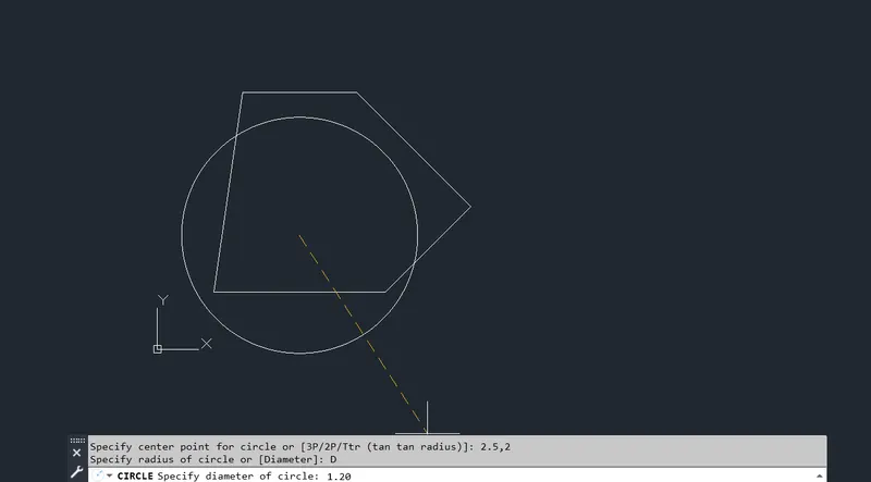
Specify the Diameter of the Circle as 1.20
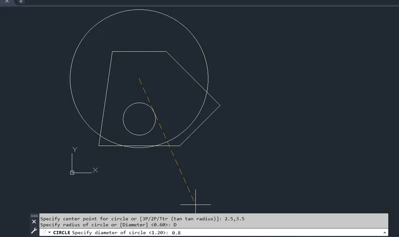
Now to create another Circle select Circle tool and Specify the center as 2.5,3.5
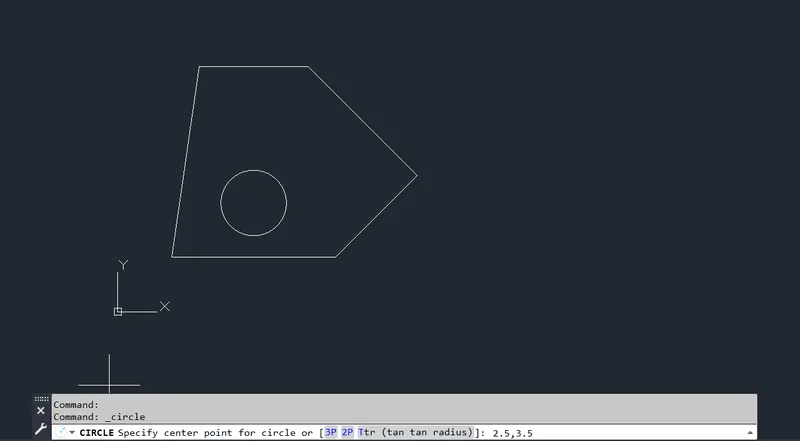
Specify the Diameter of the Circle as 0.80
Given Geometry is Created Now Check the Dimensions as per the Question
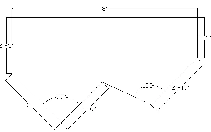
Geometry 02
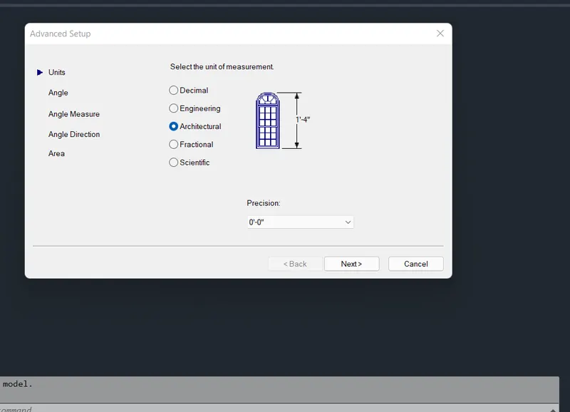
Open autoCad in Advanced Setup, Select units as Architectural and Click Next
Select The Line Tool and Specify the First Point as 10,10
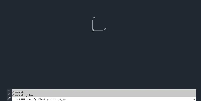
Specify the Next Point as 96,0
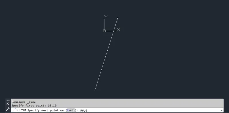
Specify the Next Point as 0,-21
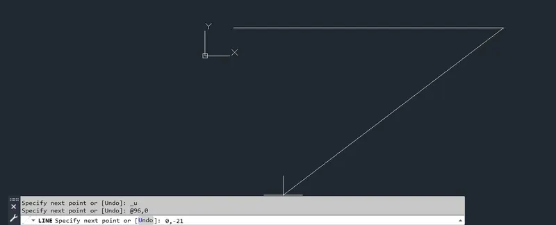
Specify the Next Point as 34<225
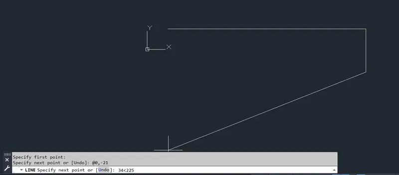
Specify the Next Point as 0,-29
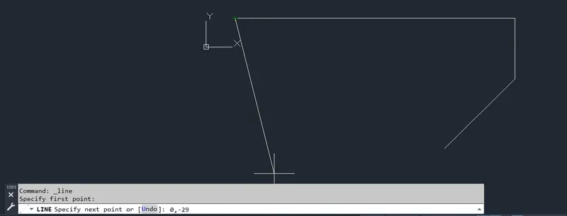
Specify the Next Point as 36<135
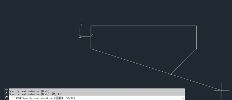
Specify the Next Point as 30<45
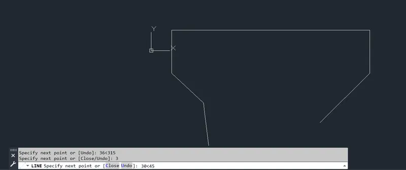
Specify the Next Point and Close The Line by selecting Close
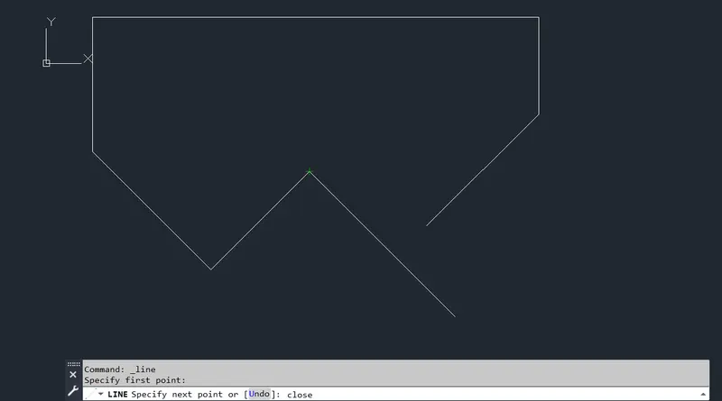
Geometry is Completed
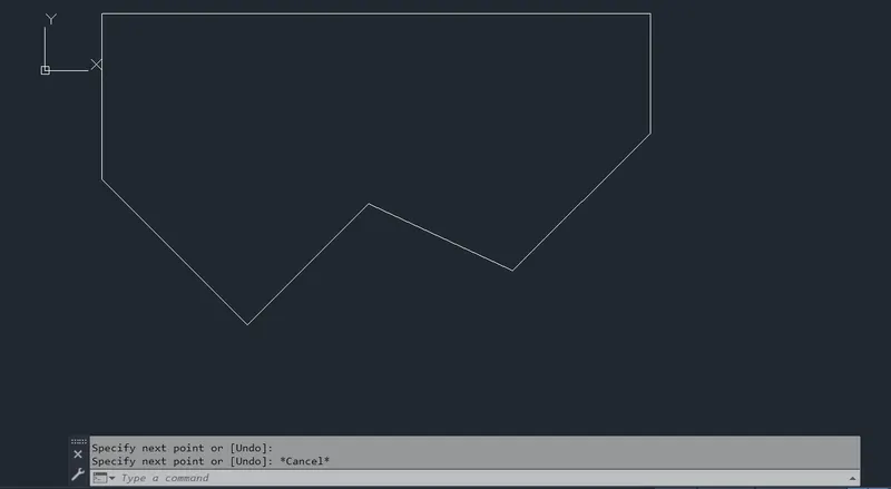
Now Check The Dimensions and angular Measurements as per the given Geometry
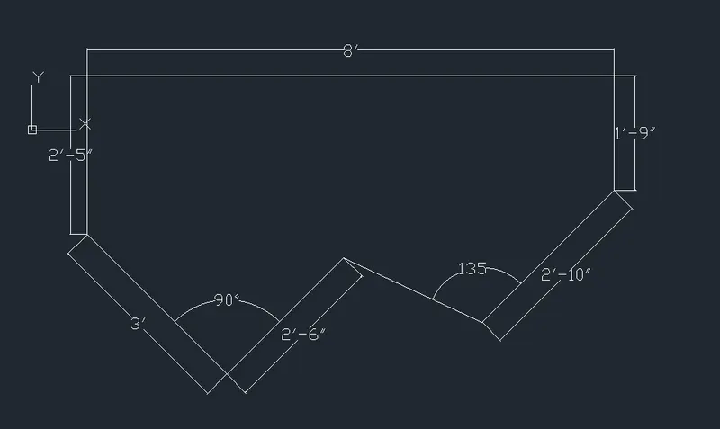
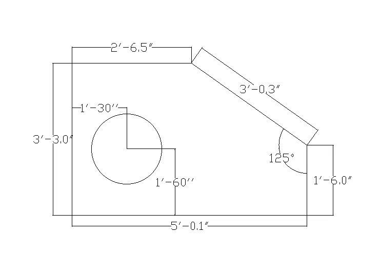
Geometry 03 :
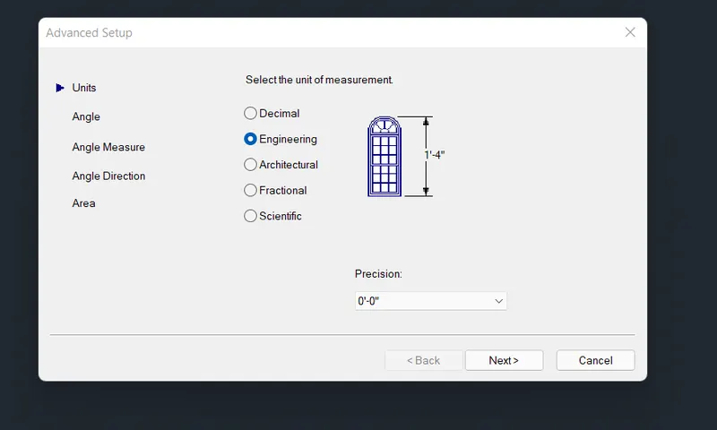
Select the unit to Engineering as shown in fig.
Select the Line tool and Specify the first point as 1,1 and then Specify the Next point as 6'0.1'',0
then specify the next point as 0,1'6''
Click on First point of the line or type 1,1 and Specify next point as 0,3'3''
S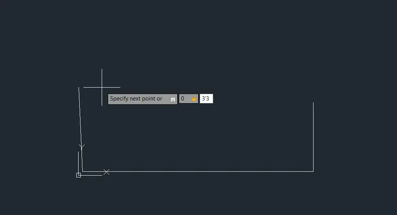
Specify the Next Point as 2'6.5,0
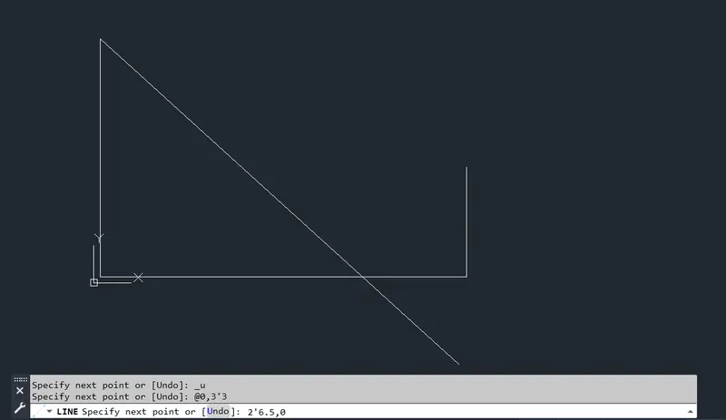
Specify the Next Point as 1'3'',1'6'' and close the Geometry
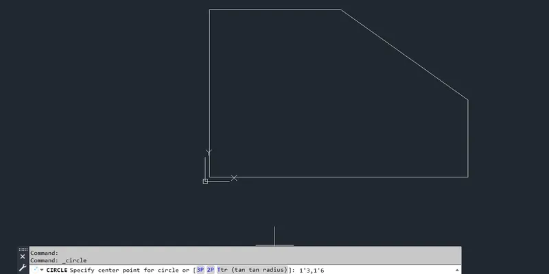
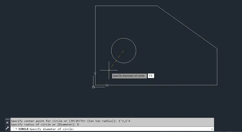
Select the Circle and specify the centre as 1'3'',1'6''
set the Diameter to 1'6''
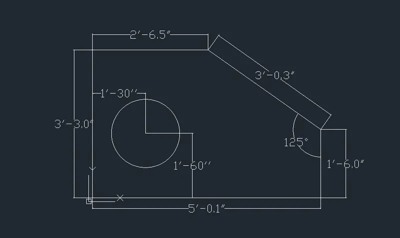
Geometry is Prepared now Check all the Dimensions
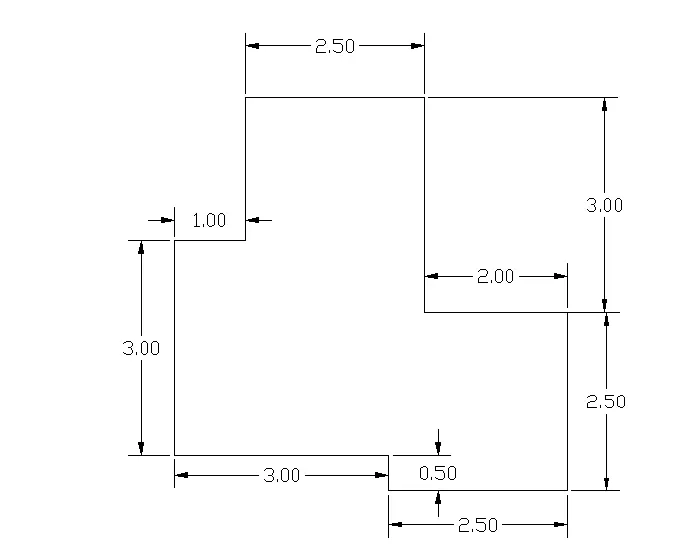
Geometry 04
Open Auto CAD and set the units to Decimal system
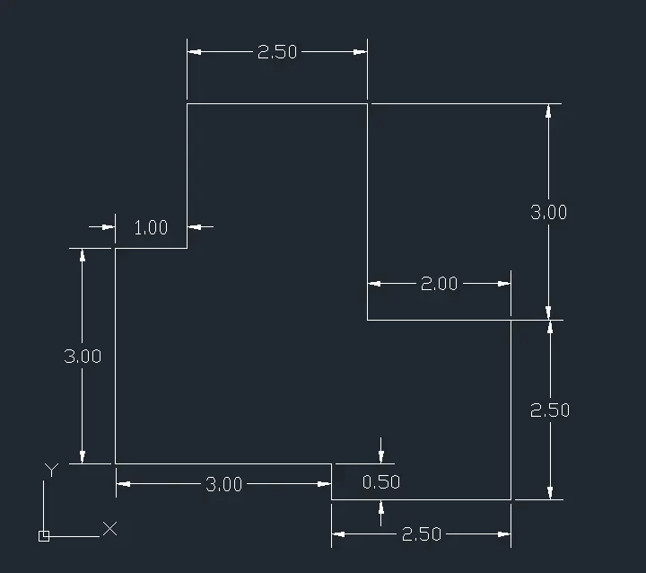
select the Line Tool and Specify the First pont as 1,1
Specify the Next point as 3,0
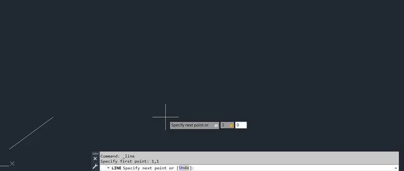
Specify the Next Point as 0,-0.5
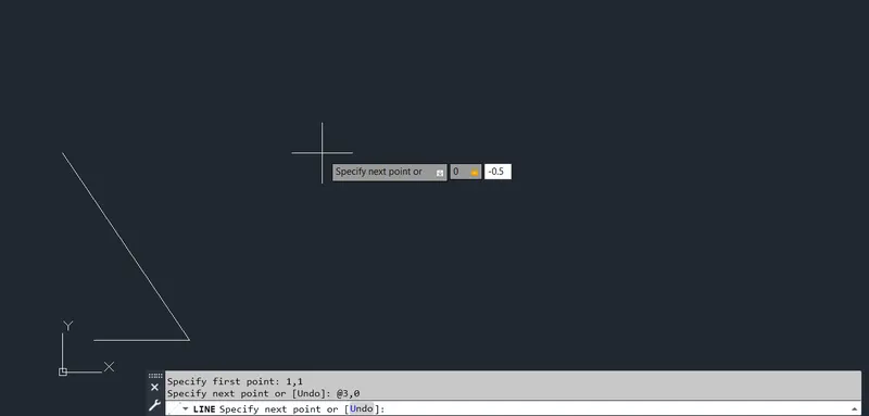
Specify the Next Point as 2.5,0
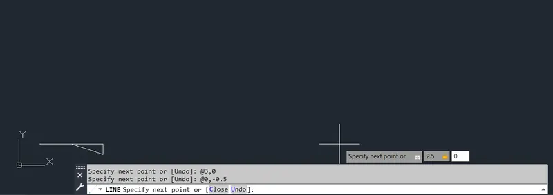
Specify the Next Point as 0,2.5
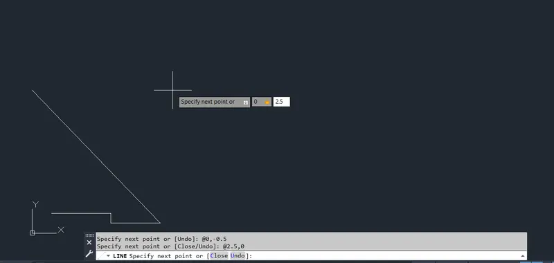
Specify the Next Point as -2,0
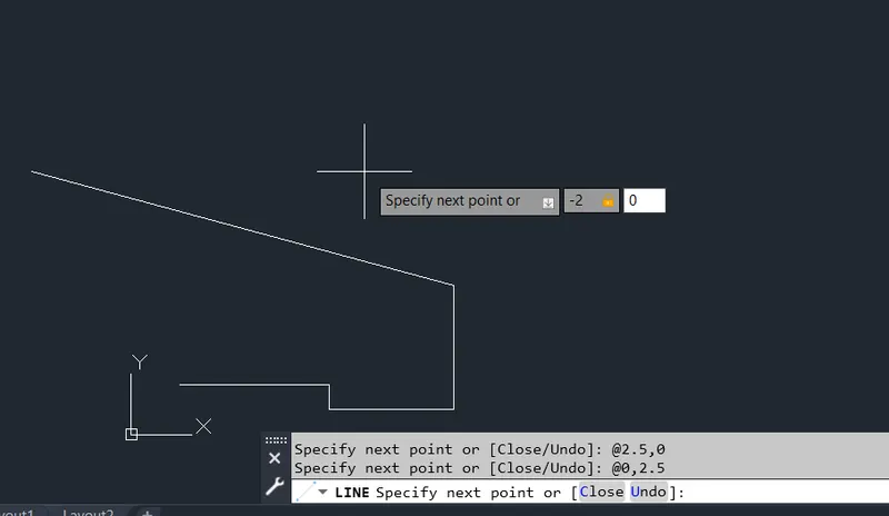
Specify the Next Point as 0,3
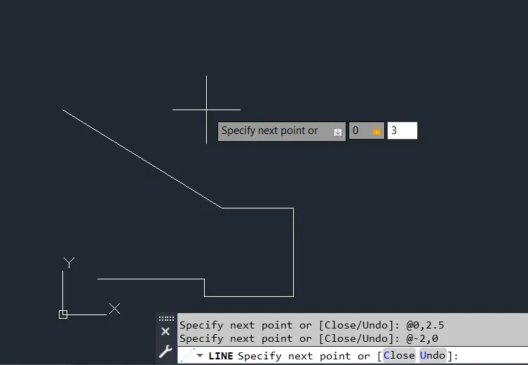
Specify the Next Point as -25,0
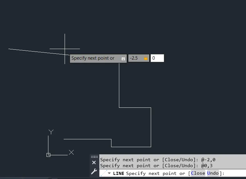
Specify the Next Point as -1,0 and close the Geometry by with Close command
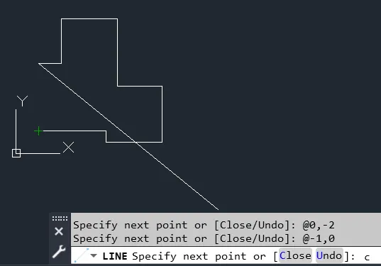
Now Geometry is prepared Check all the Dimensions
Geometry 05
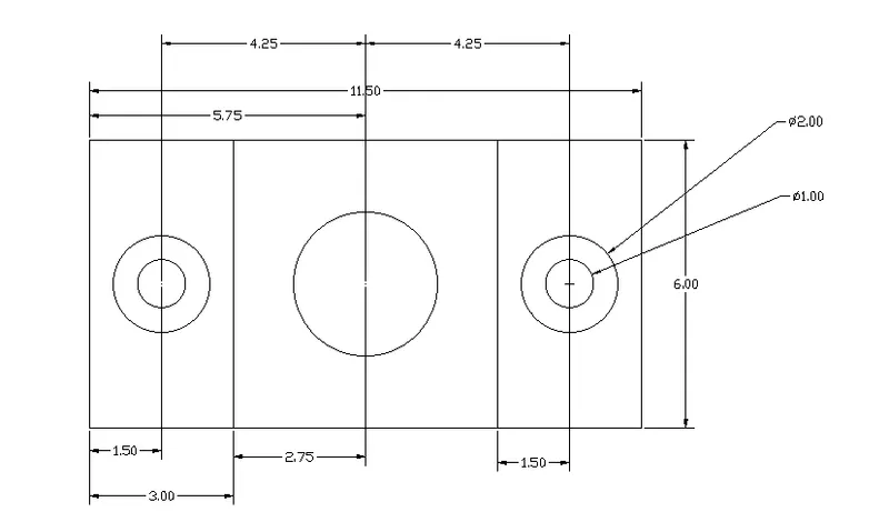
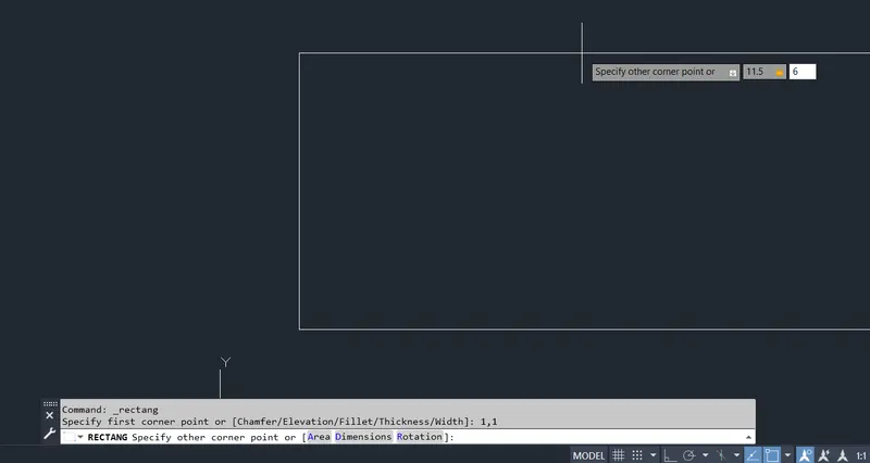
Select Rectangle tool and Specify First corner point as 1,1
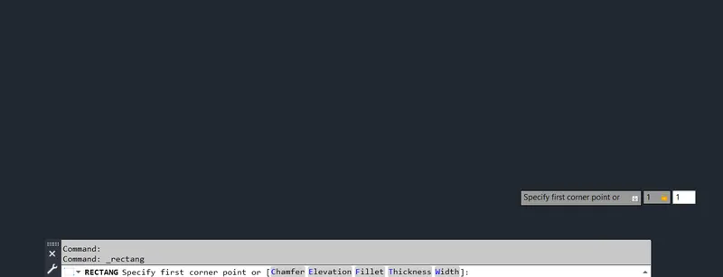
Specify other corner point as 11.5, 6
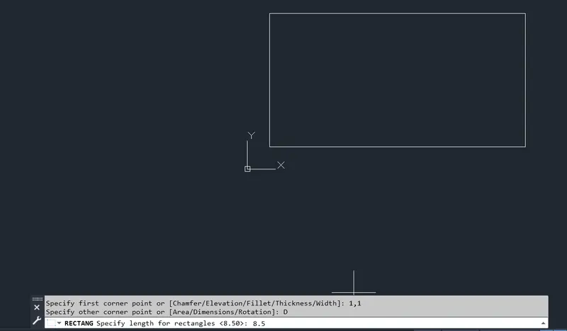
Select Rectangle tool again and select corner point as 1,1
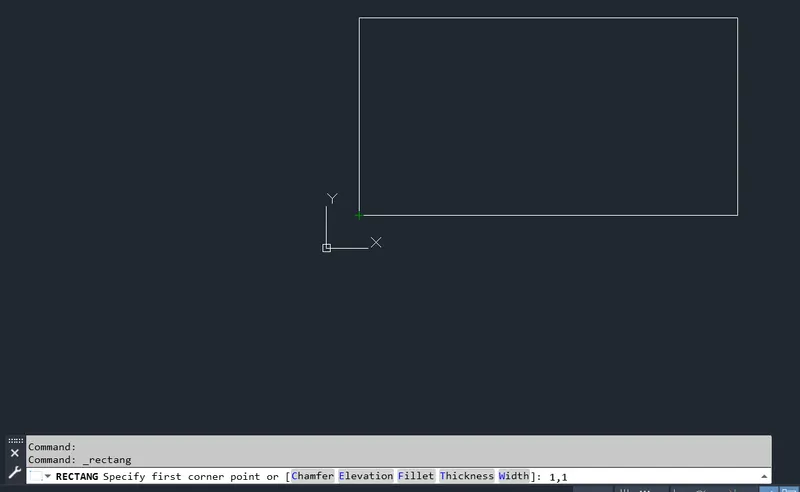
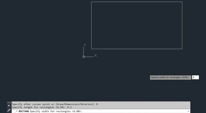
Specify length as 8.5
Specify width as 6
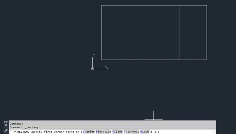
Again select Rectangle tool and Specify First point as 1,1 and length as 3
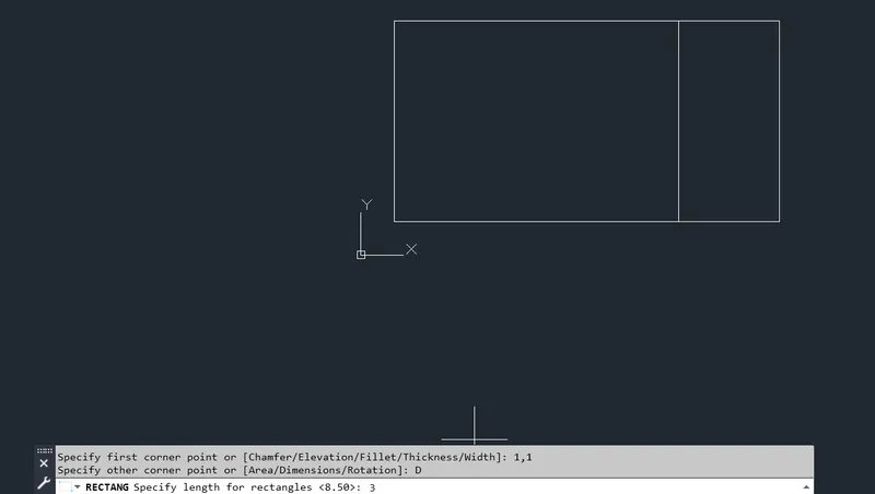
Specify width as 6
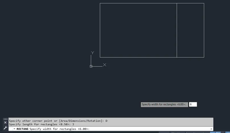
Select CIRCLE Tool 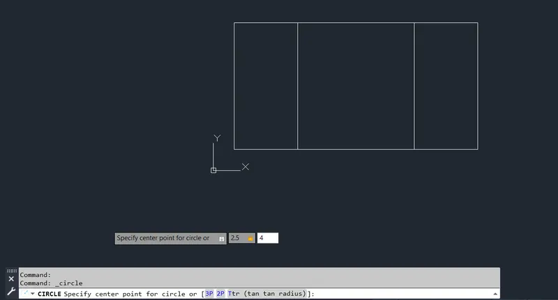
Specify center point as 2.5,4
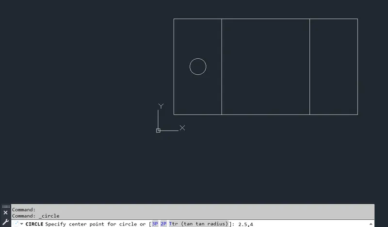
Select CIRCLE Tool and Specify center as 11,4 and offset distance First CIRCLE as 0.5 and create a offeset
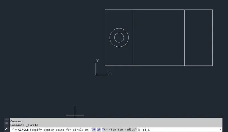
Select CIRCLE Tool and Specify center and offset distance as 0.5 and create a offset
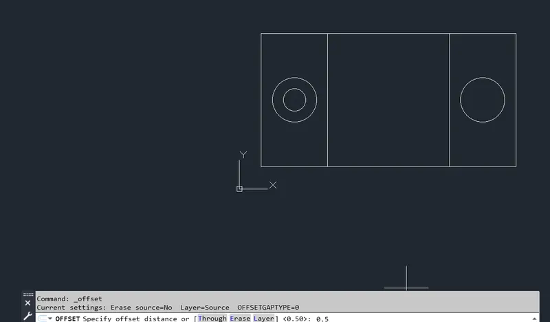
Select CIRCLE Tool and Specify center point as 6.75,4
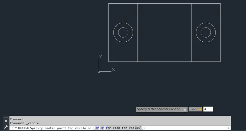
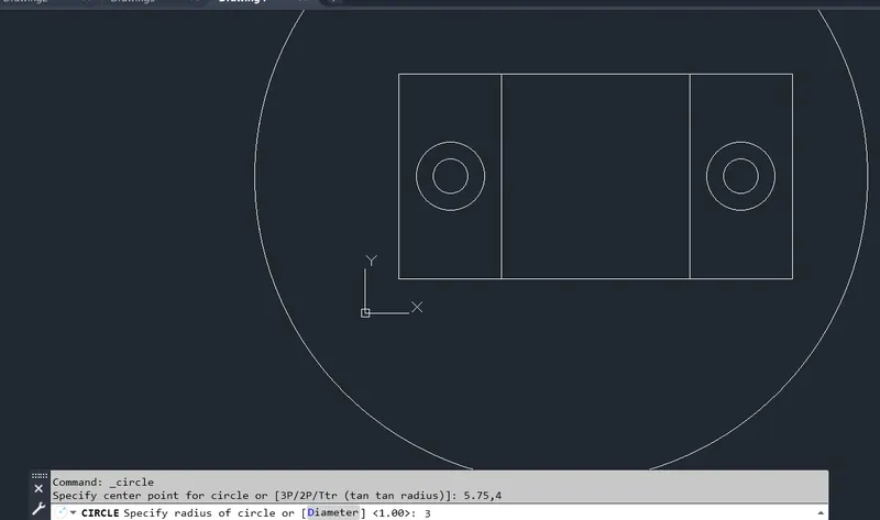
Enter the radius as 3 and create a Circle
Now Geometry is Created and Check all the Dimensions 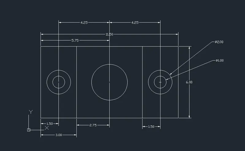
Geometry 06
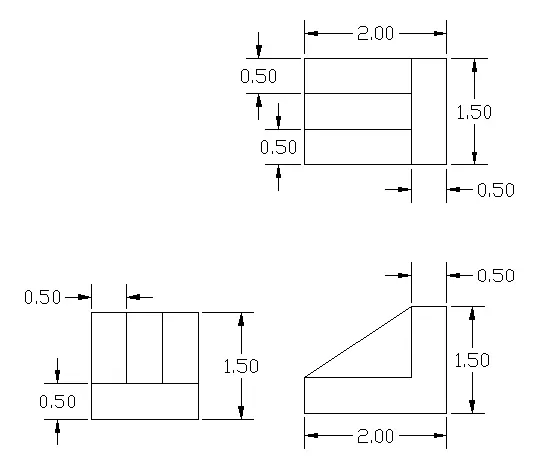
Select Rectangle tool and Specify First point as 1,1
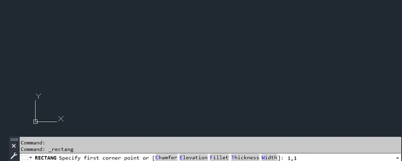
Specify other corner point as 1.5,1.5
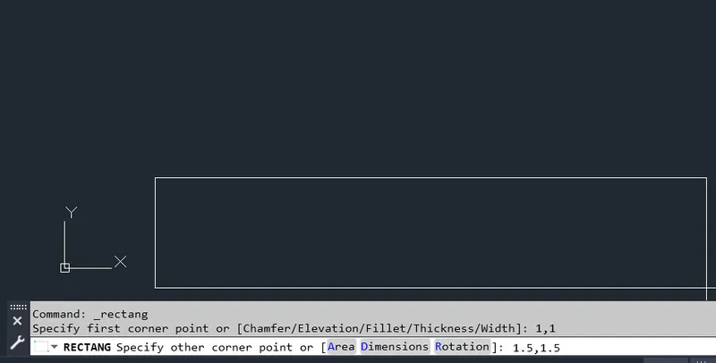
Select Rectangle tool and Specify the First Point as 1,1
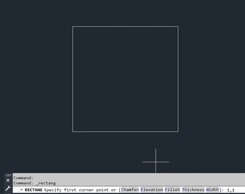
Specify other corner point as 1,1
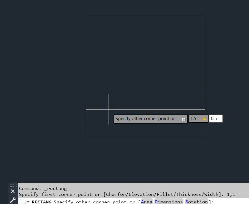
Specify other corner point as 1.5,0.5
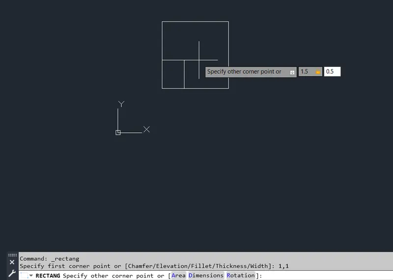
Select Rectangle tool and Specify First point as 1,1 and Specify next point as 1,1.5
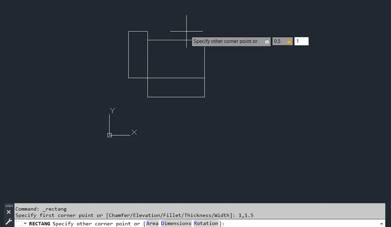
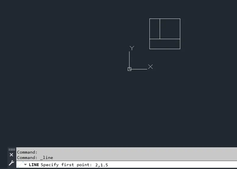
Select line tool and Specify First point as 2,1.5
Specify Next Point as 2,2.5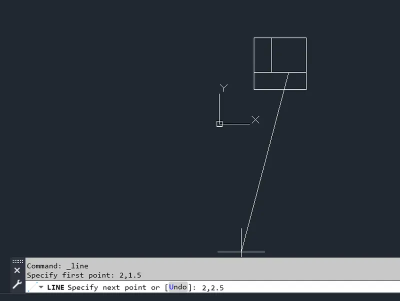
Select Rectangle tool and Specify First point as 1,1
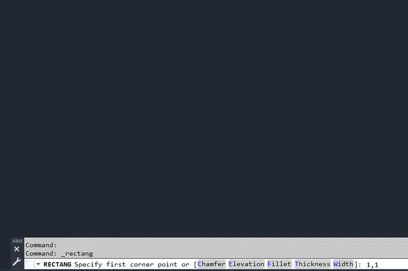
Specify size of Rectangle as2, 1.5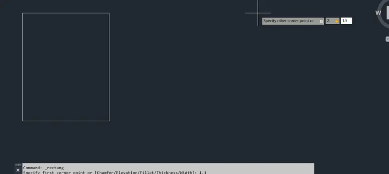
Select Rectangle tool and Specify First point as 12.5,1
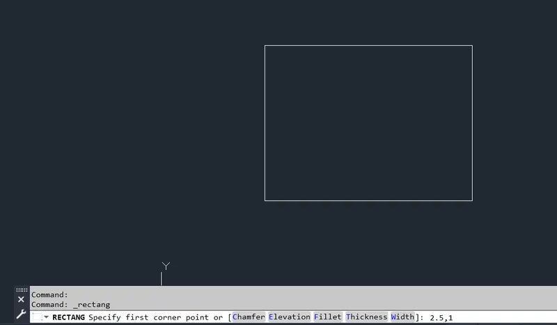
Specify other corner point as 0.5,1.5
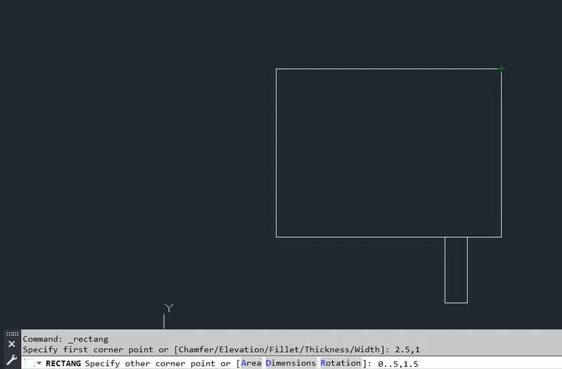
Select Rectangle tool and Specify First point as 1,1 and other corner point as 1.5,1
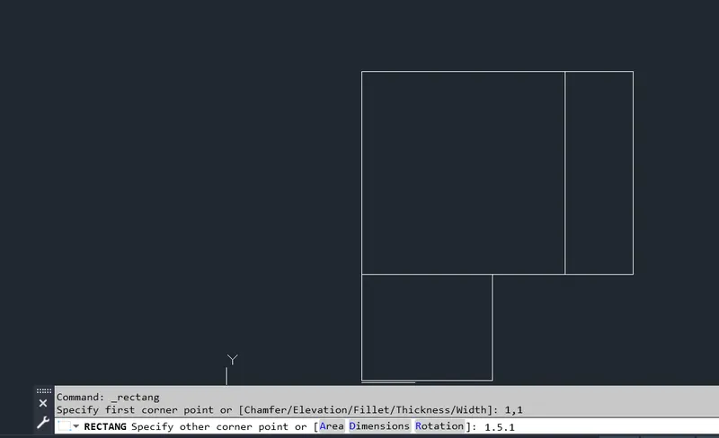
Select Rectangle tool again and Specify First point as 1,1
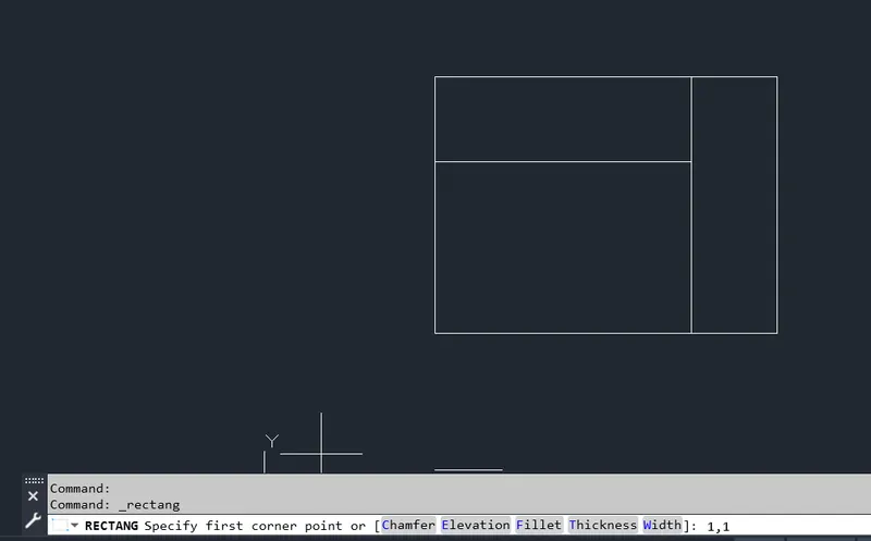
Select other corner point as 1.5,0.5
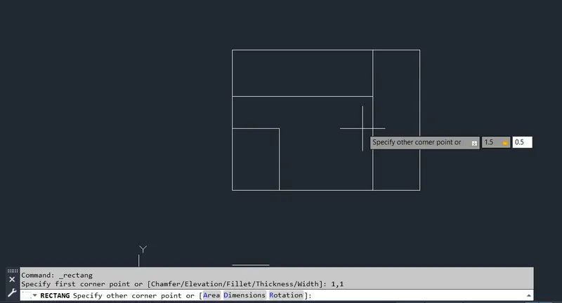
Geometry is Created and Check for the Dimensions
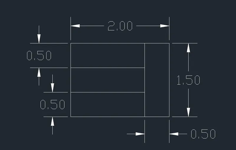
Select Line Tool Specify the First Point as 1,1 and Next Point as 2,0
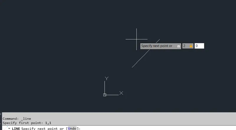
Specify Next Point as 0,1.5
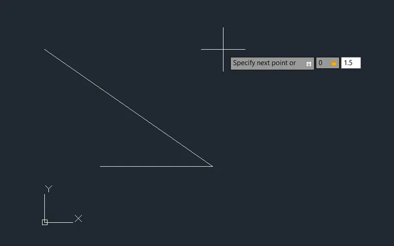
Specify Next Point as -0.5,0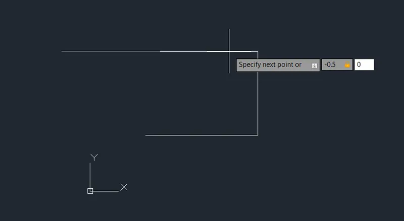
Specify Next Point as 0, -1
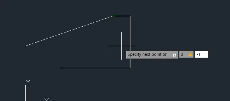
Specify Next Point as-1.5,0
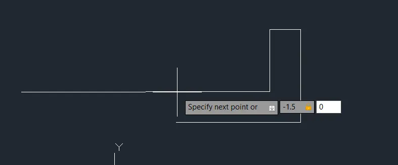
Select line tool and Specify First point as 1,1
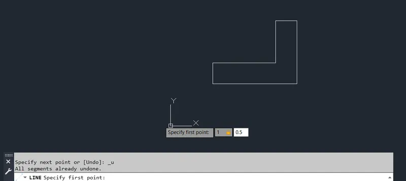
Next Point as 1.5,1
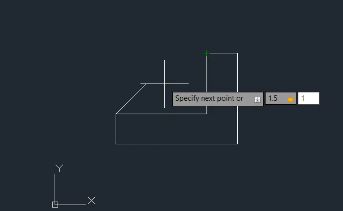
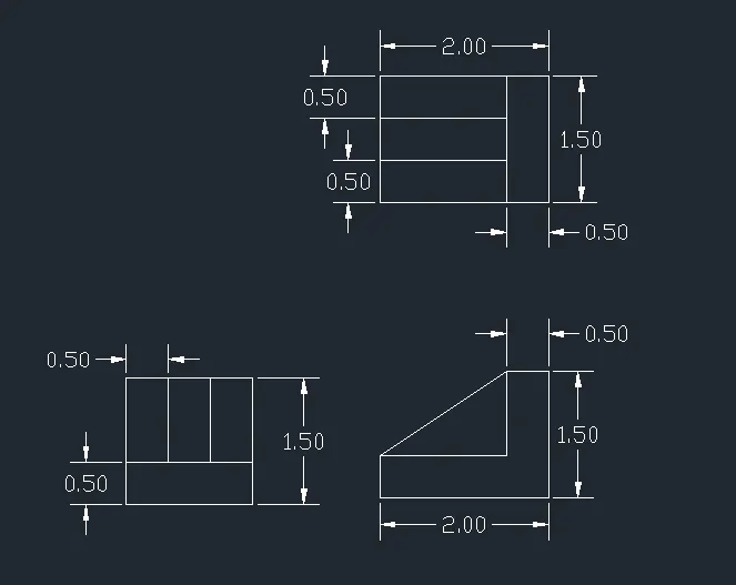
Geometry is Created Now Check the Dimensions
Geometry 07
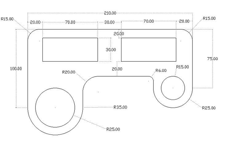
Select Polyline and Specify First point as 1,1
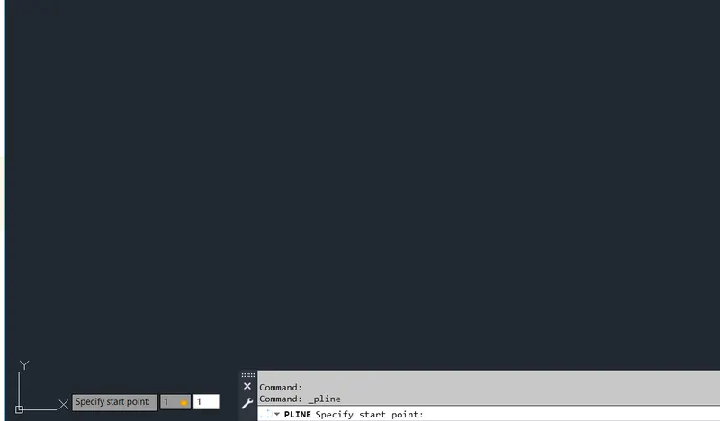
Specify length as 0,100
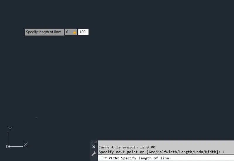
Specify Next Point as 210,0
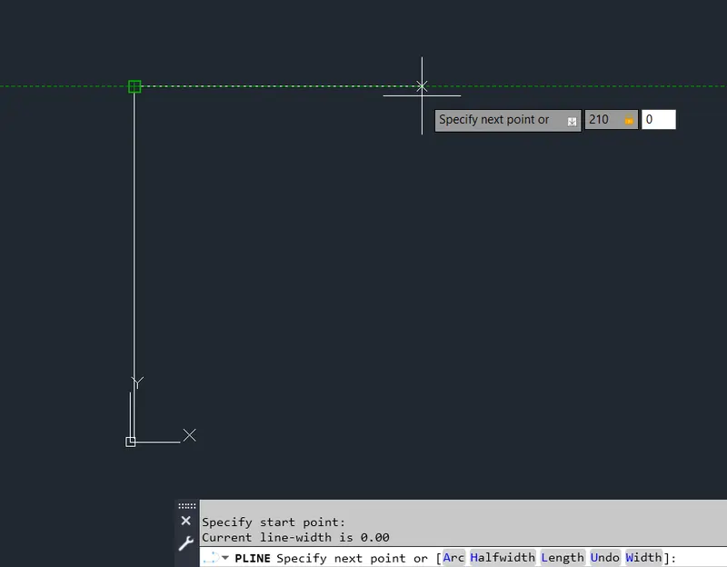
Specify Next Point as 0, -0.75
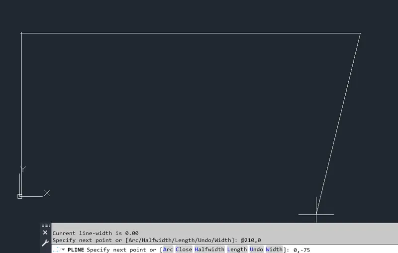
Select Arc at command bar and Specify the radius as 25
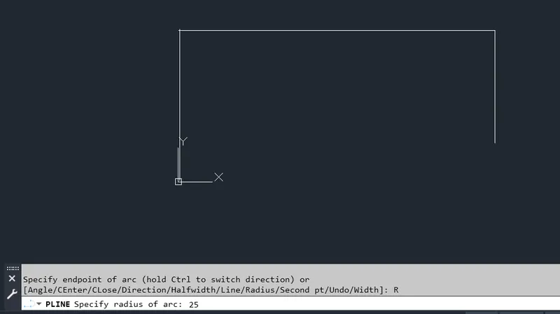
Specify Next Point as 0,15
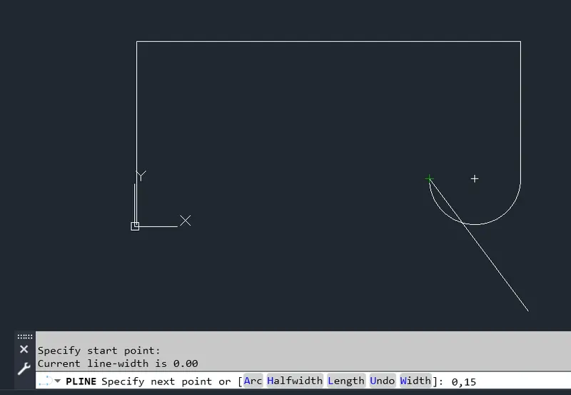
Specify Next Point as-90,0
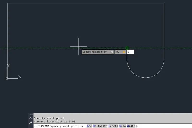
Specify Next Point as 0,-40
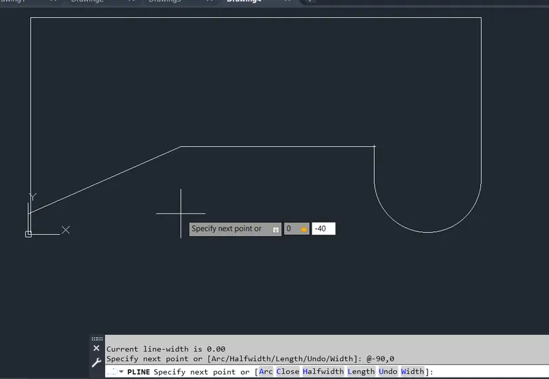
Select arc at command bar and select radius as 35
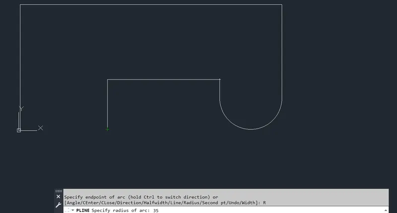
Select CIRCLE Tool and Sp Diameter as 50
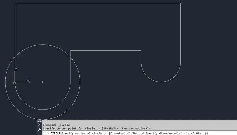
Specify radius of another Circle as 30
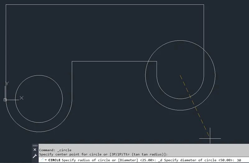
Select Rectangle tool and Specify First point as 20,0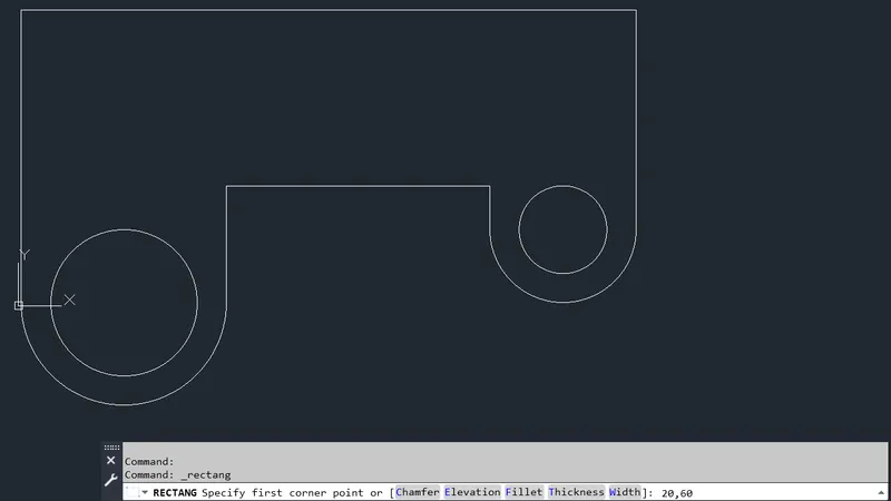
Specify other corner point as 70,30
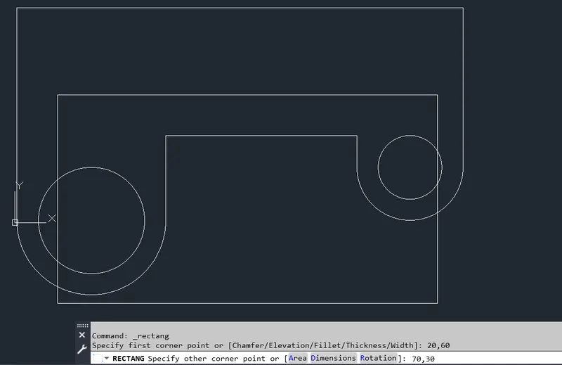
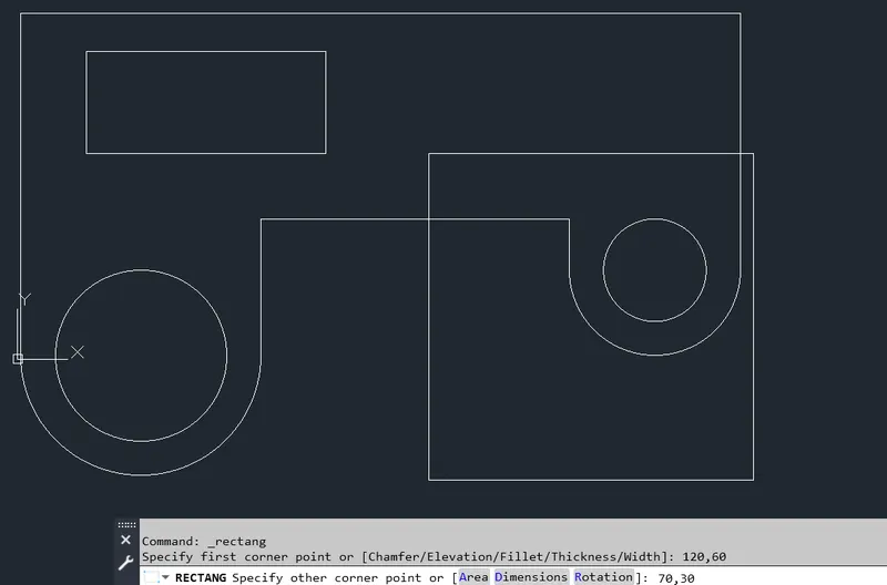
Select Rectangle tool and Specify First point as 120,60
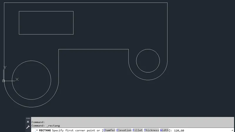
Specify other corner point as 70,30
Select Fillet tool and Specify Fillet radius as 15
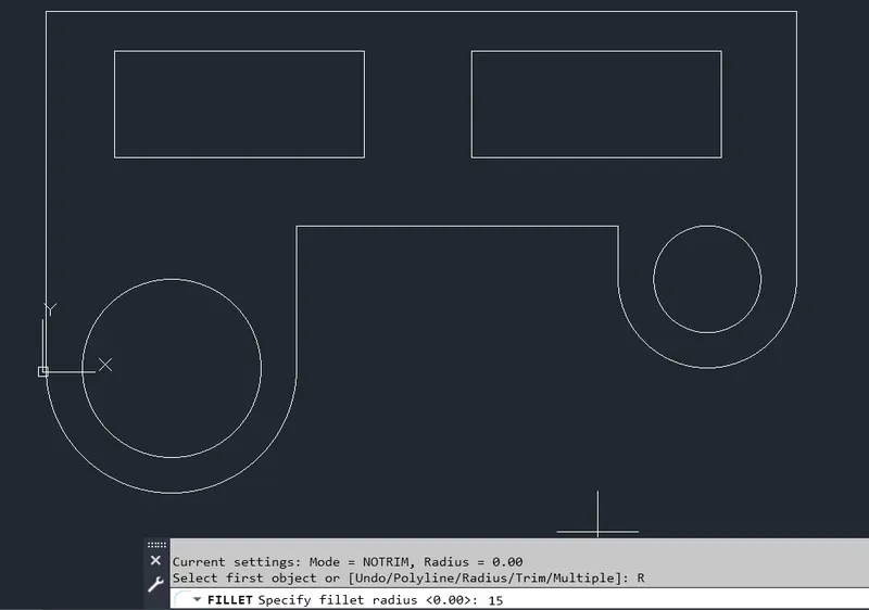
Specify Fillet radius as 6
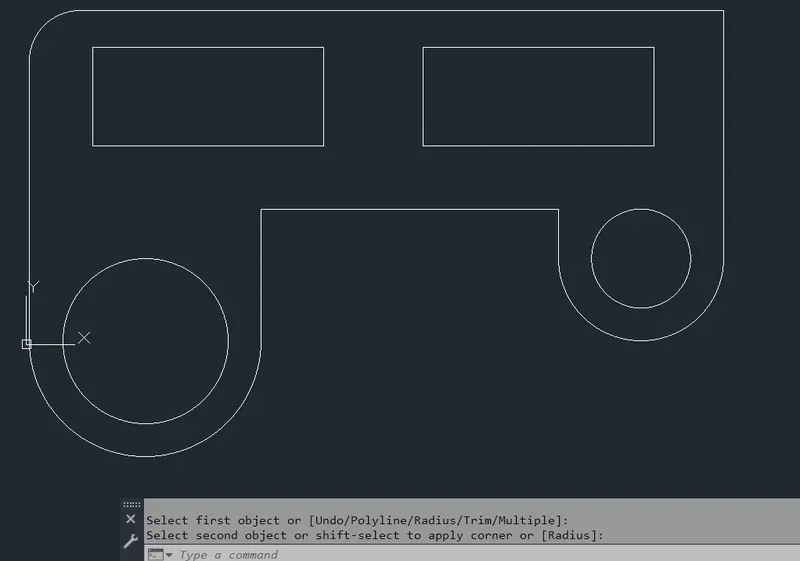
Select fillet tool and Specify Radius
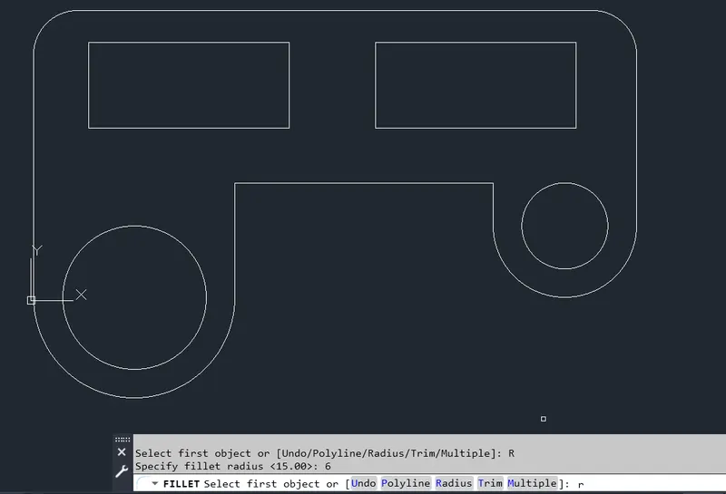
Select radius as 20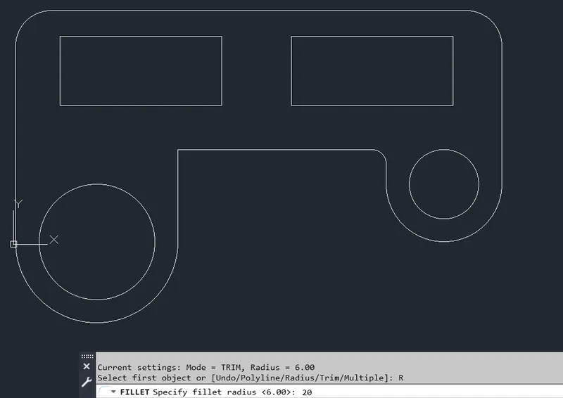
Now Geometry is Created Check all the Dimensions
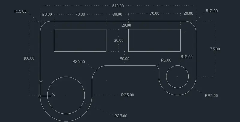
Geometry 08
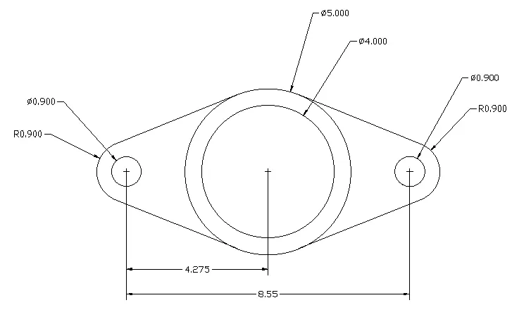
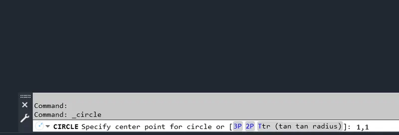
Select CIRCLE Tool and Specify center as 1,1
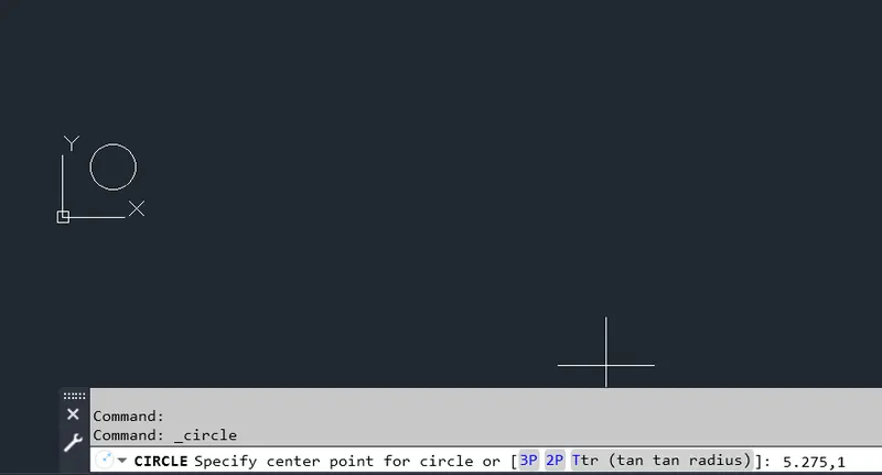
Specify the centre point of Circle as 5.275,1
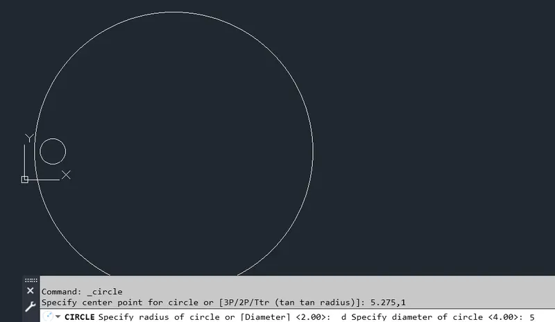
Specify radius as 5
Select CIRCLE Tool and Specify center as 5.275,1
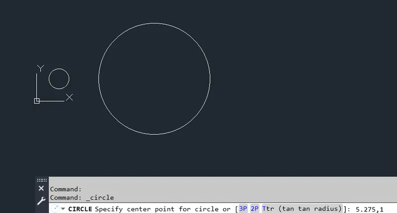
Specify radius as 4
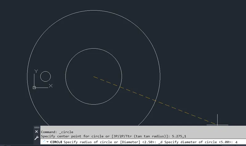
Select CIRCLE Tool and Specify center as 9.55,1
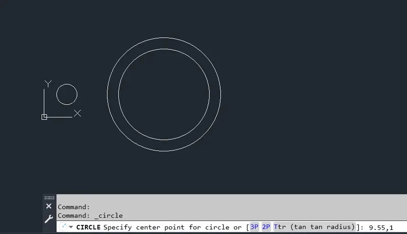
Specify Diameter of the Circle as 0.9
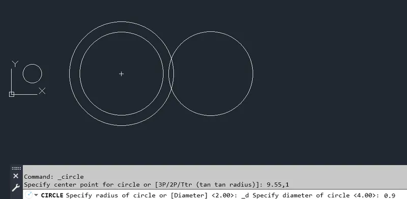
Select CIRCLE Tool and Specify center as 1,1 and radius as 0.9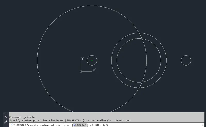
Select tool and Specify center as 9.55,1 and Specify Radius as 0.9
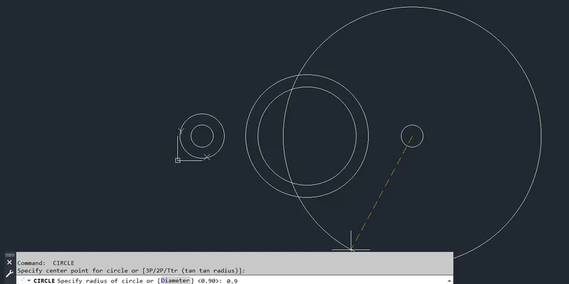
Select line tool and type tan to create tangent between two circles 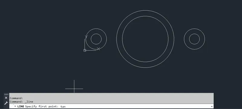
similarly create tangents between the Circles as per the drawing 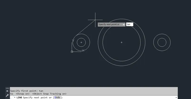
similarly create tangents between the Circles as per the drawing
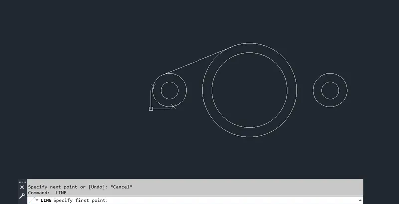
similarly create tangents between the Circles as per the drawing 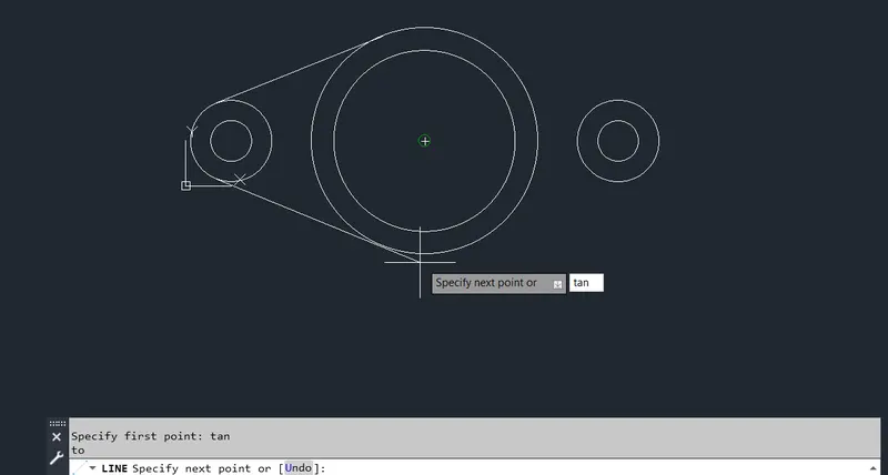
similarly create tangents between the Circles as per the drawing 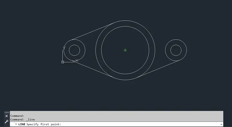
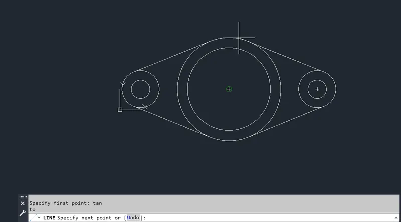
Select Trim tool
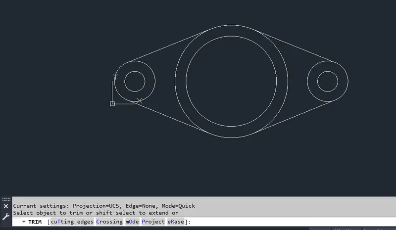
Trim the Highlighted lines
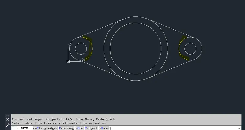
Now Geometry is Created Check all the Dimensions
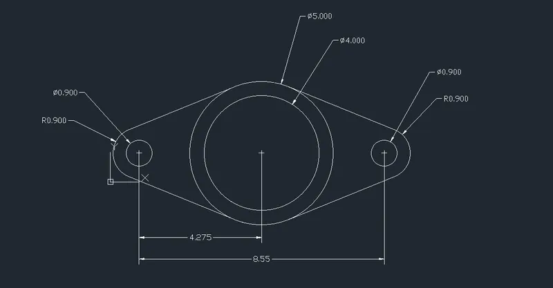
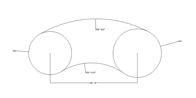
Geometry 09
Select CIRCLE Tool and Specify center as 1,1
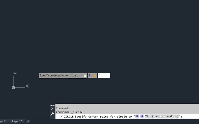
Select radius as 32'6",1
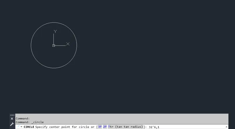
Specify radius as 9'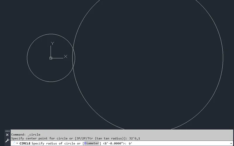
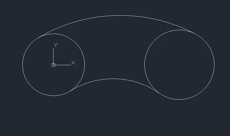
now Select First point of the first Circle to create tangent Circle
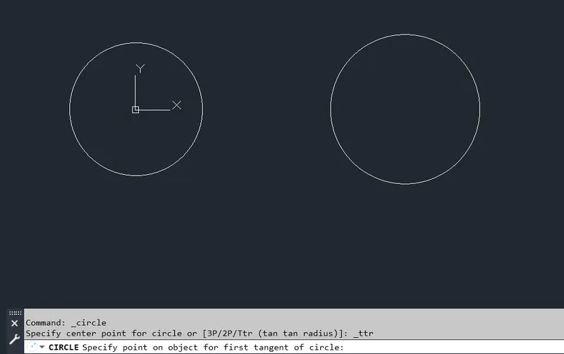
Specify point on other Circle
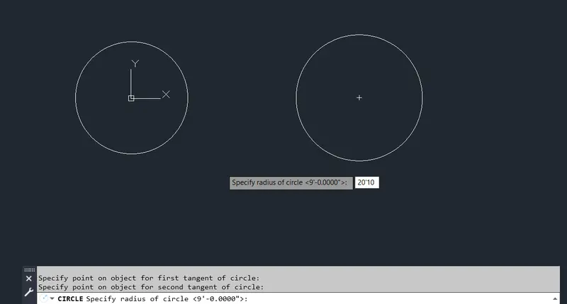
Create Circles tangented above and below to the Circle
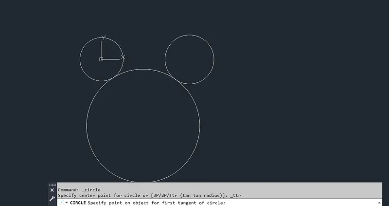
Select Trim tool and Trim the Highlighted part of the Circle
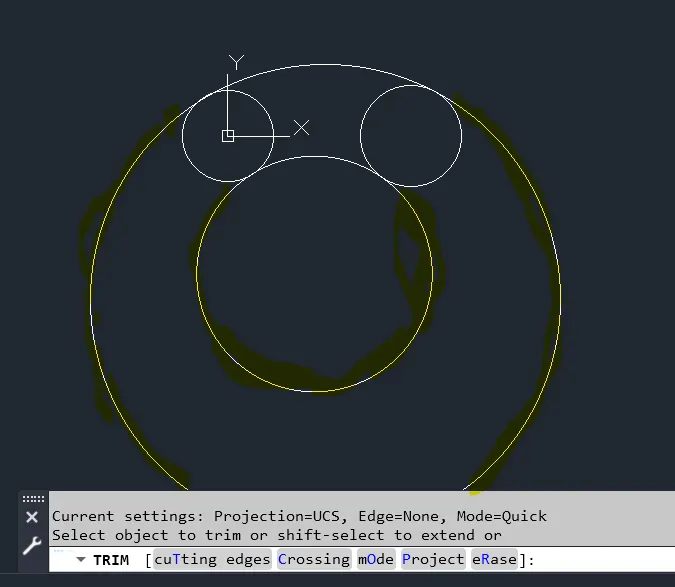
Now Geometry is Created Check all the Dimensions

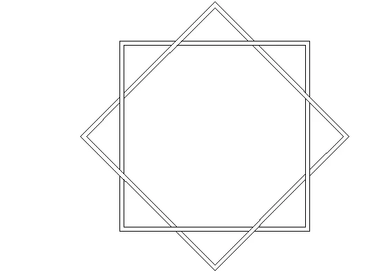
Geometry 10
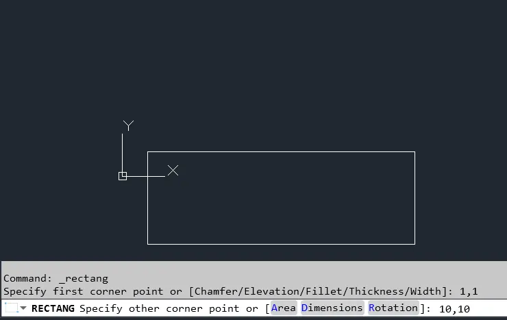
Select Rectangle tool Specify First point as 1,1
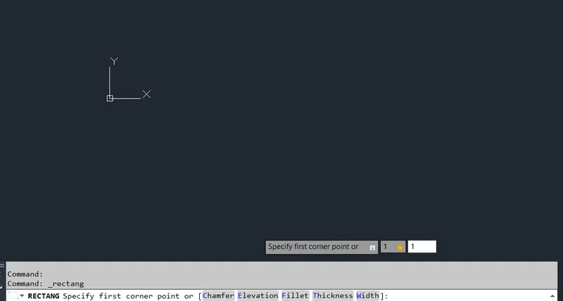
Specify other corner points as 10,10
Select Offset tool and Specify offset distance as 0.5
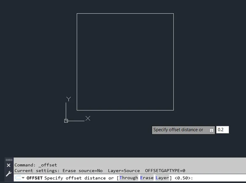
Create offset by selecting Rectangle by clicking outside of Rectangle
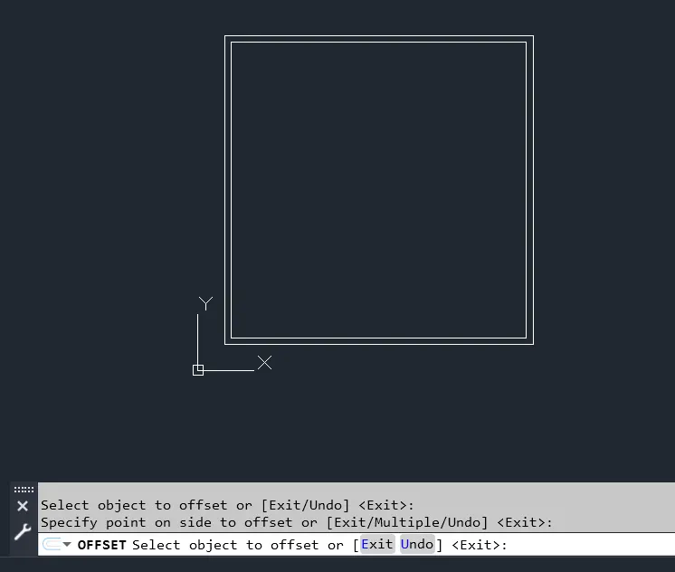
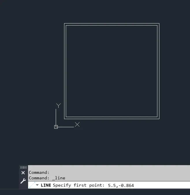
Select Line Tool and Specify First point as 9<45
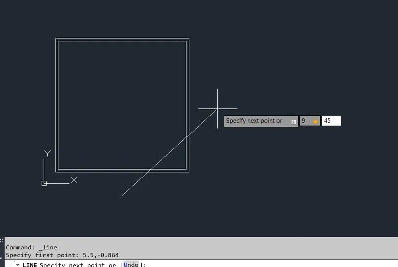
Specify Next point as 9<135
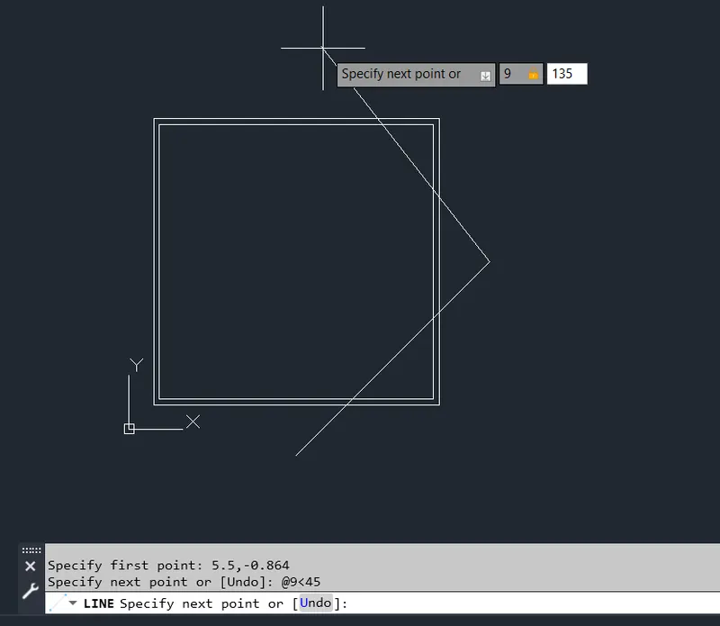
Specify Next Point as 9<225
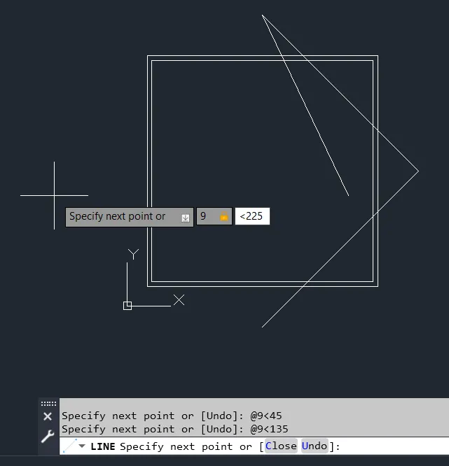
Close the Geometry by selecting Close Option or just type c
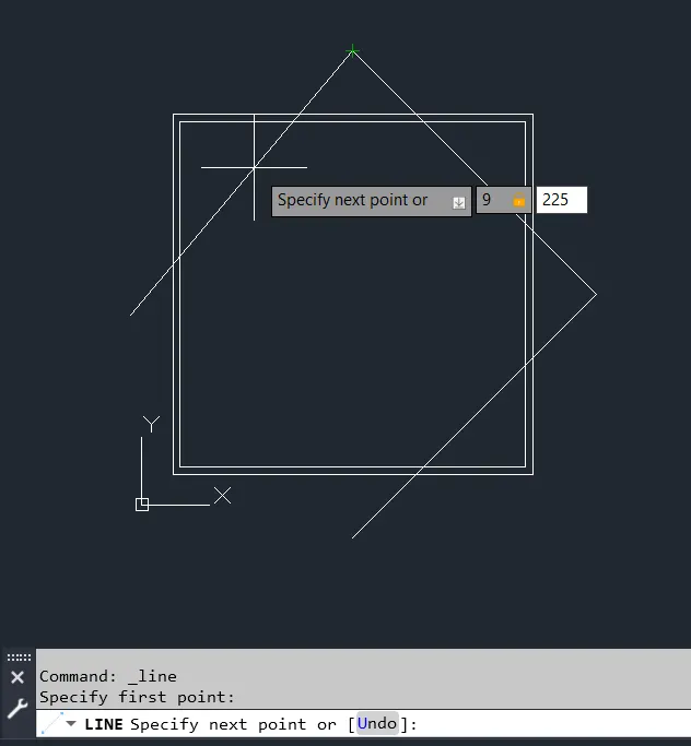
now Rectangle Created Select offset tool
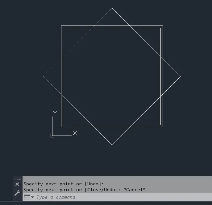
Now set the offset distance as 0.2
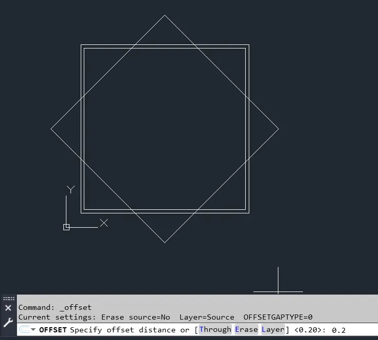
Click the Rectangle and drag out to create a offset
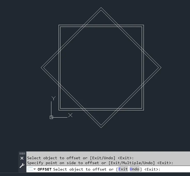
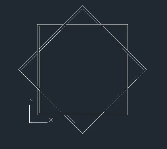
now Trim the overlapped lines by selecting Trim option 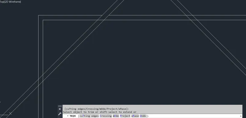
Select the Line which supposed to be Trim and click Enter.
Geometry is Created
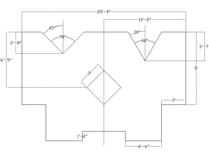
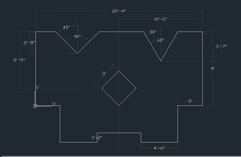
Geometry 11
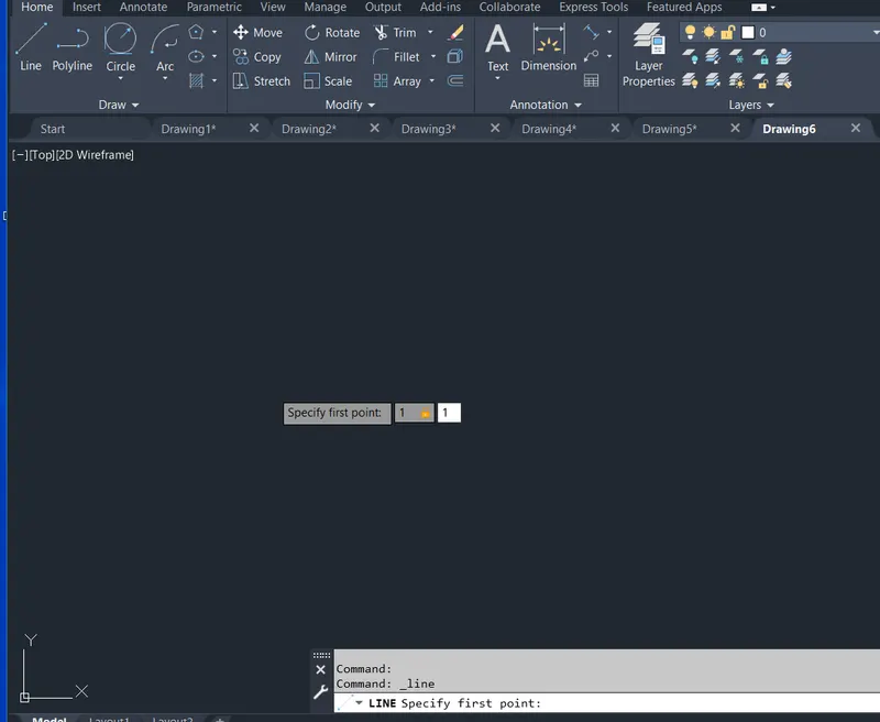
Select Line Tool and Specify First point as 1,1
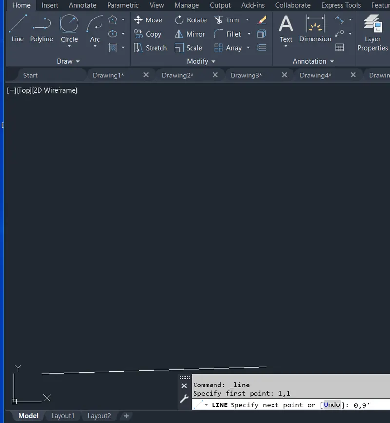
Specify Next Point as 0,9'
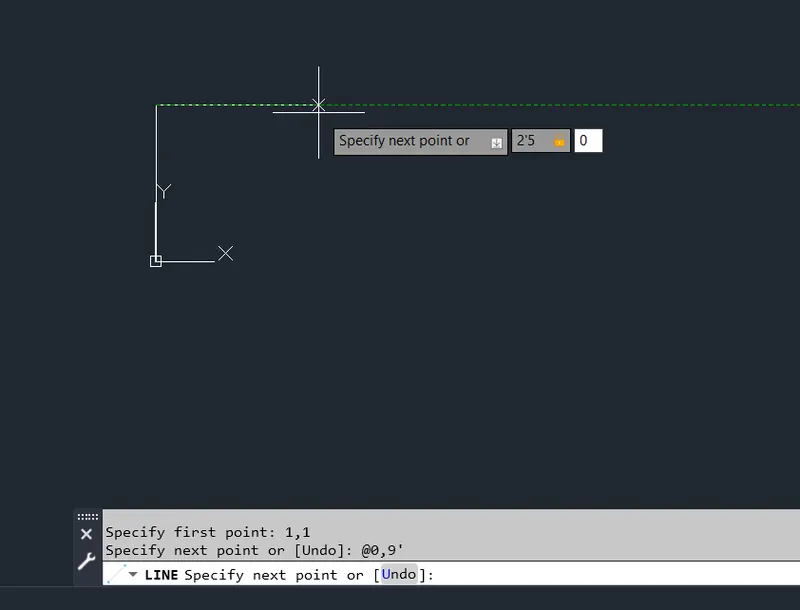
Specify Next Point as 2'5",0
Specify Next Point as 3'9"<315
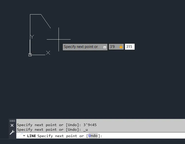
Specify Next Point as 3'9"<45
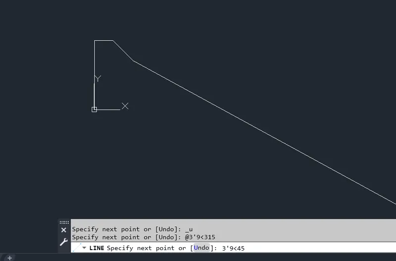
Specify Next Point as 2'5,0
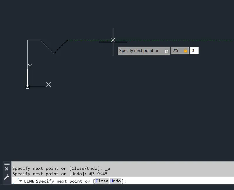
Specify Next Point as 0,4'6"
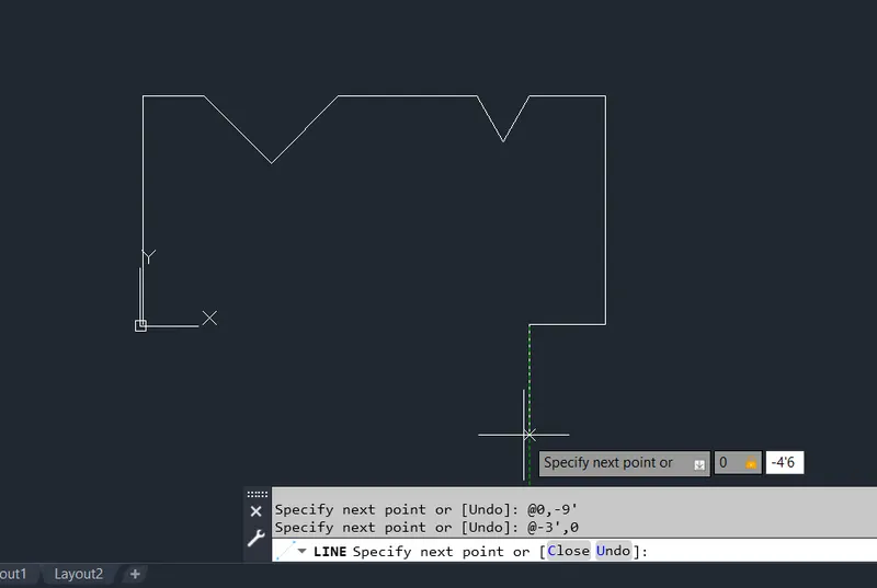
Specify Next Point as-4'6",0
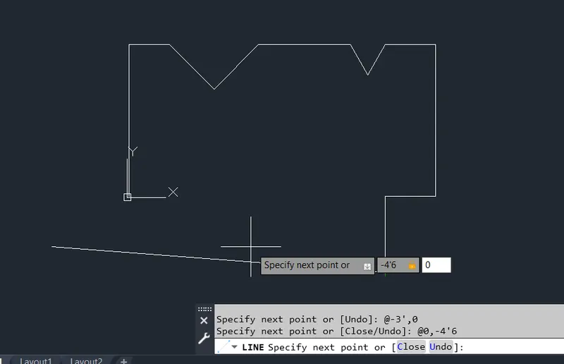
Specify Next Point as 0,1'2"
Next Point as-5'4",2
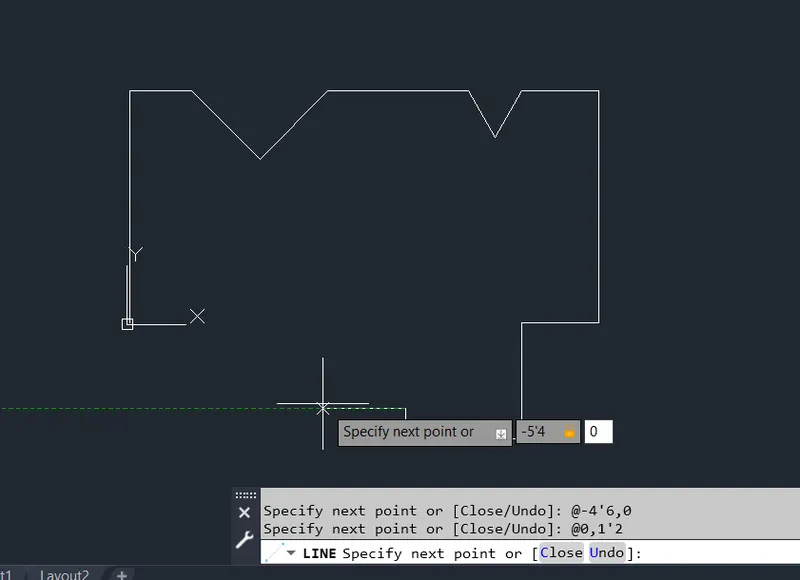
Select Line Tool Specify the First Point as 3'<45
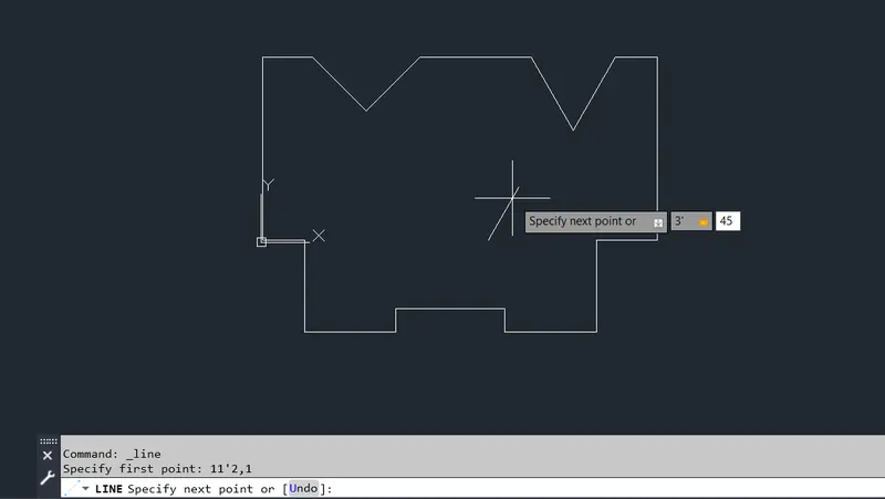
Specify the Next Point as 3'<135
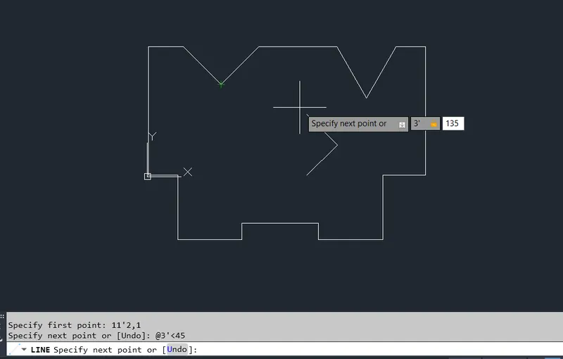
Specify the Next Point as 3'<225
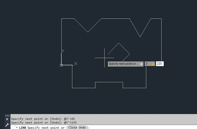
The Geometry is Created Now Check the Dimensions
RESULT : The Given Geometries are Drafted by Using Line tool, Rectangle, Circle , Chamfer and Fillets with the help of Co ordinate systems in AutoCAD
Final Drawings are Shown Below