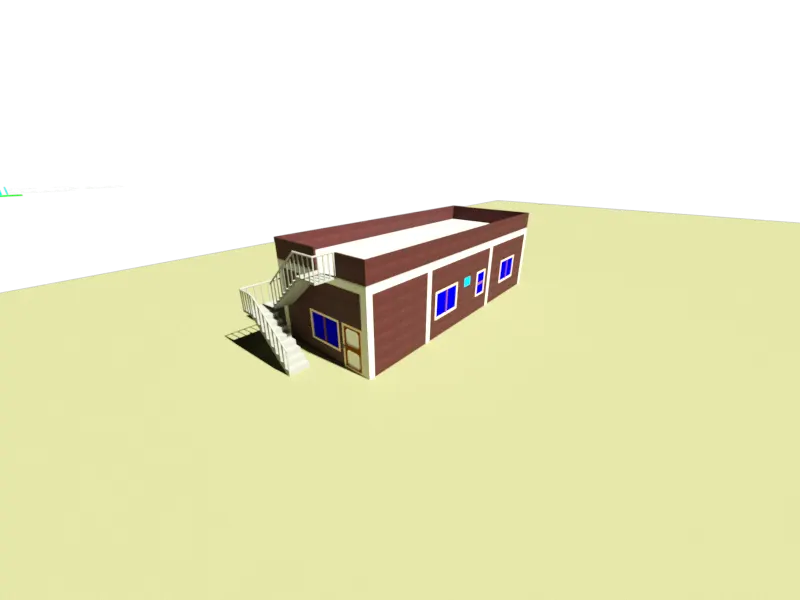
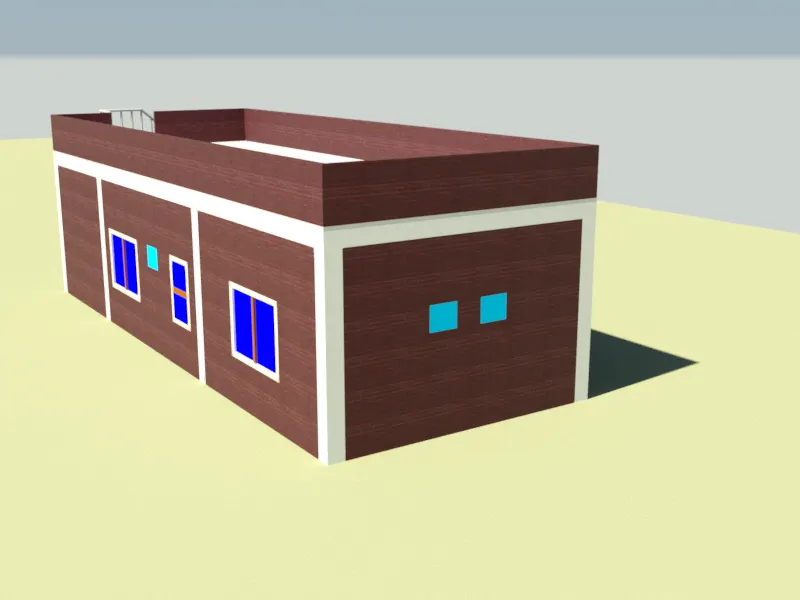
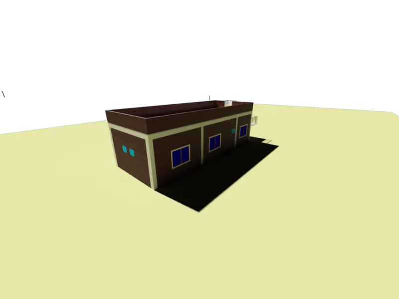
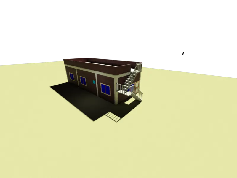
Project 2_Creating a 3D rendered model for a Residential Building in AutoCad
AIM: To draw a 3D-rendered model for a residential building in Autocad
PROCEDURE:
1. First and foremost change the unit to decimal and mm
2. Now create the layer for the model
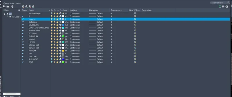
3. Now create the plan for the building with the help of the layer created
4. BUILD-UP size of the building is 15450x6000mm
- External wall thickness= 230mm
- internal wall thickness=100mm
- Door= 1000x2000mm
- W/c Door = 900x1800mm
- Window= 2000x1500mm
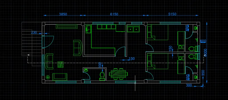
5. After Creating the plan with internal and external walls Orient the column in the respective place with C/C distance
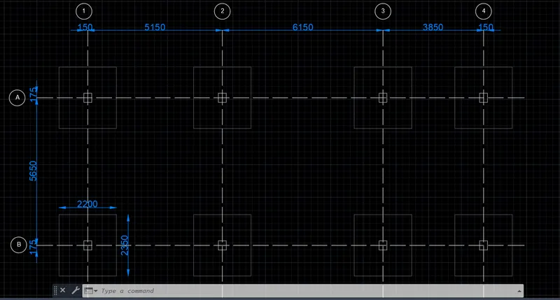
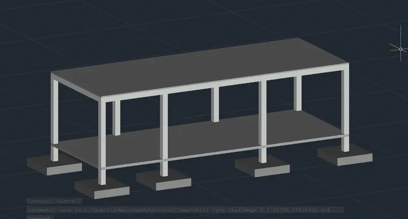
6. Now start Orienting the footing as per the column orientation. The size of the footing is shown in the figure
CENTERLINE PLAN
3D VIEW
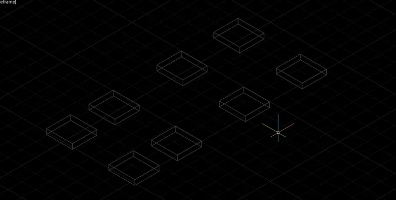
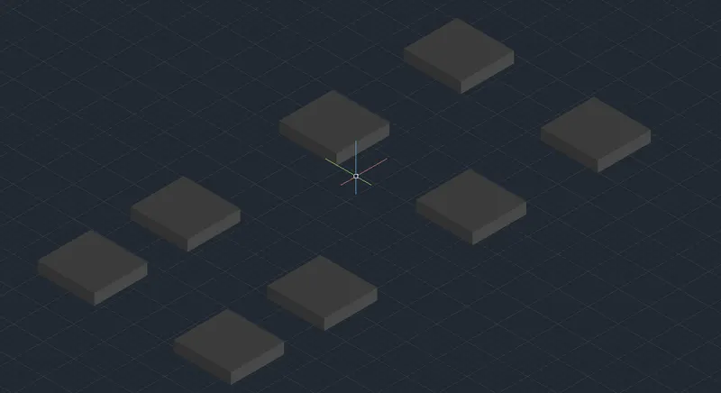
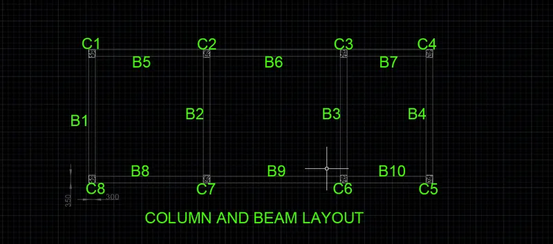
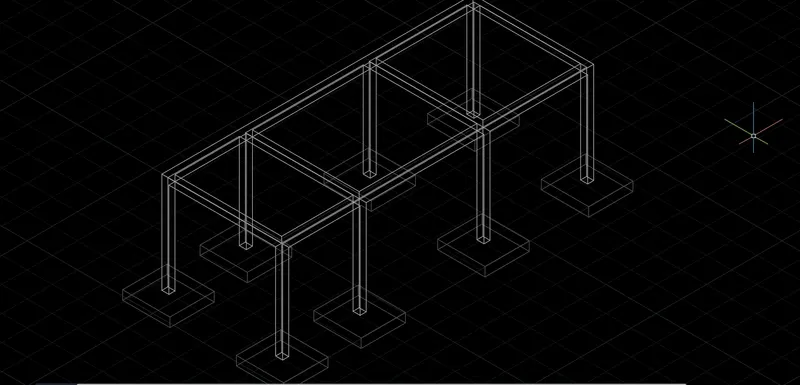
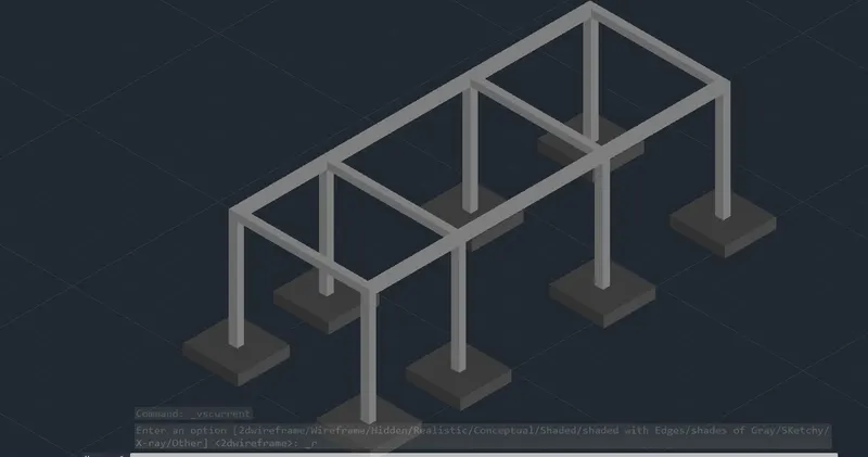
7. The size of the column is 300x350mm. As per the column, orientation Erect the column from each footing for 4000mm height, 900mm below the ground level, and remaning above the ground level
Floor-level beam has been provided for size 300x300mm details are shown in the figure
BEAM AND COLUMN LAYOUT
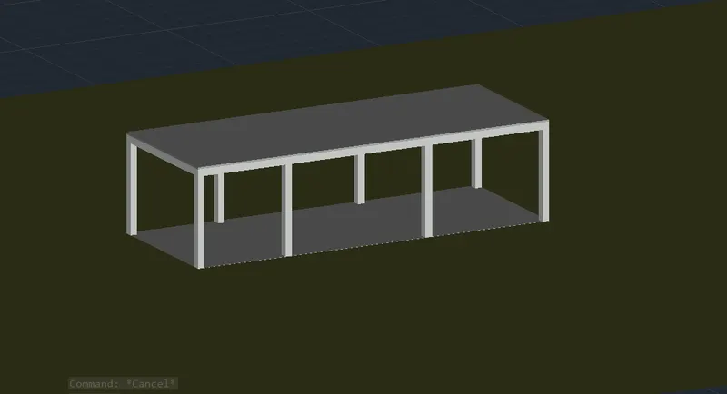
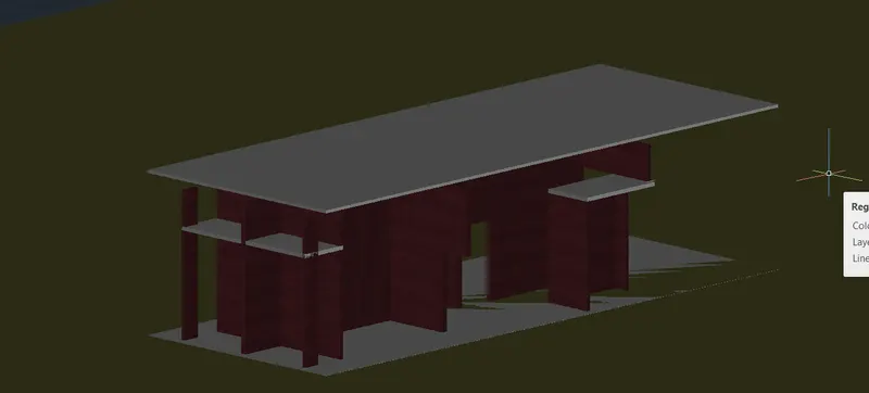
8. Now create the floor and roof slab
- Roof slab= 150mm
- floor slab= 100mm
- There are slabs over W/C which are going to be After the construction of W/C walls
9. As per the Plan and layout
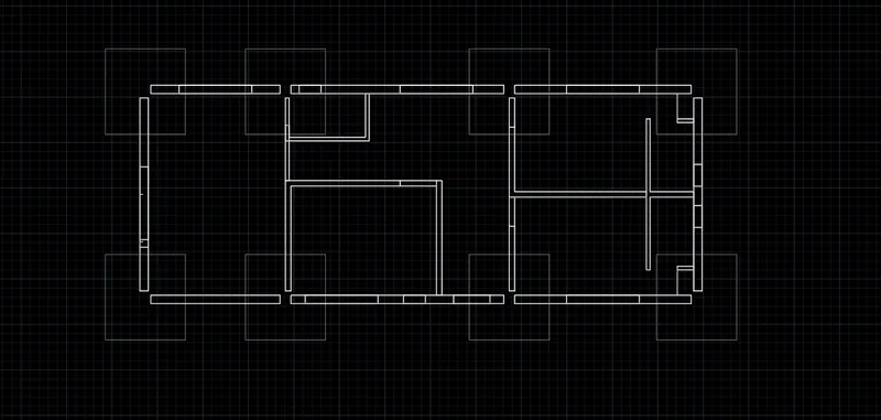
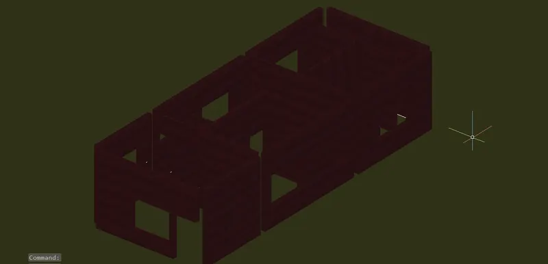
- External wall = 230mm
- INternal wall = 100mm
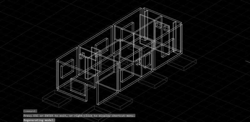
- Height = 2700 for GL
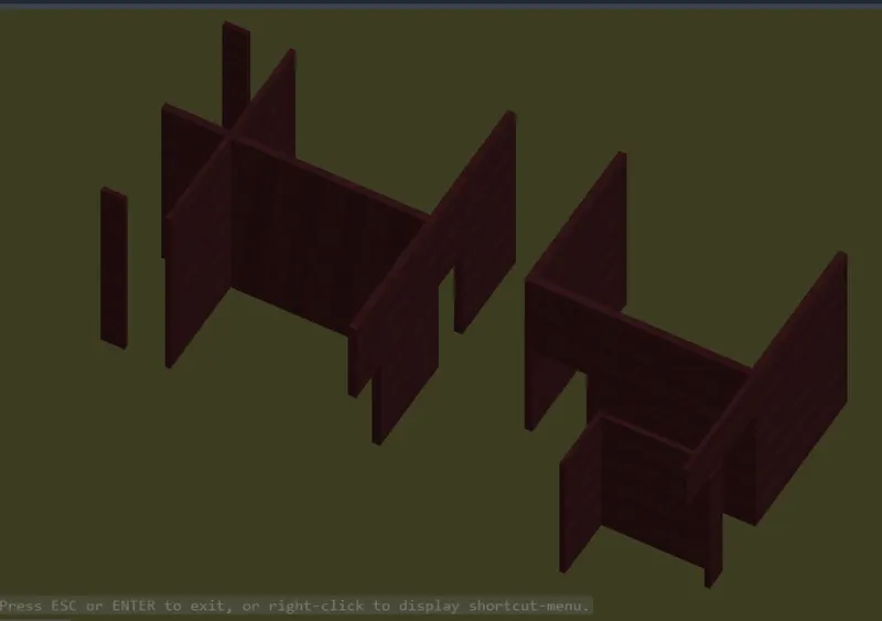
- determining the Position of the wall and making it a single entity and then converting it into a region with the help of region command
- Also create a parapet wall for a height of 1000mm and 100mm thick
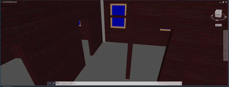
- Providing Openings in the External & internal walls for Doors, windows, and Ventilation dimension
- External wall thickness= 230mm
- internal wall thickness=100mm
- Door= 1000x2000mm
- W/c Door = 900x1800mm
- Window= 2000x1500mm
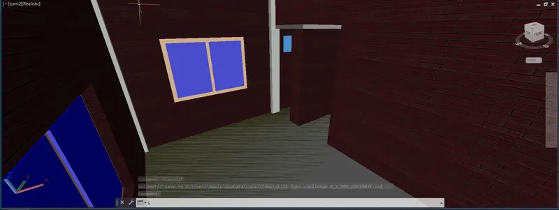
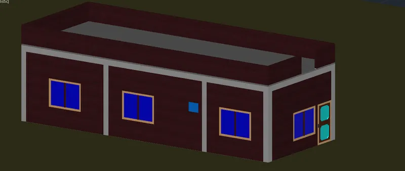
10. Creating a Staircase with Railing for the Terrace approach
- Rasir= 175mm
- Tread= 300mm
- Width= 900mm
- 1st Landing height= 2000mm
- Railing height= 1000mm
- Create the side face of the staircase and join it with the help of the join command then make them a region and then extrude them for 1000mm
- For railing create them with the help of the cylindrical command for the height of 1000mm, and for handrail connect every top portion of the pole with the help of Polyline and then draw a circle, now with the help of the Sweep command convert that into handrailing
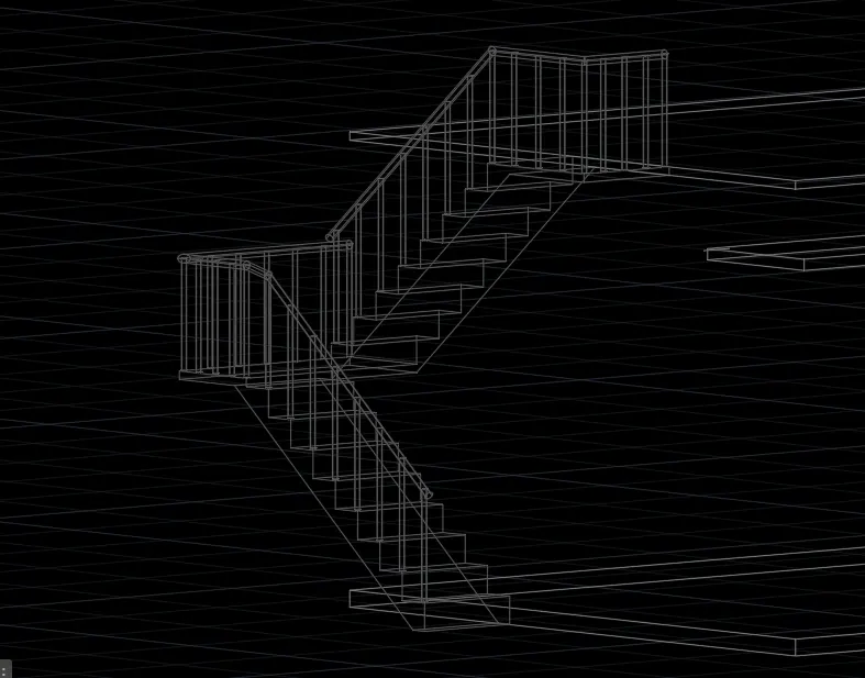
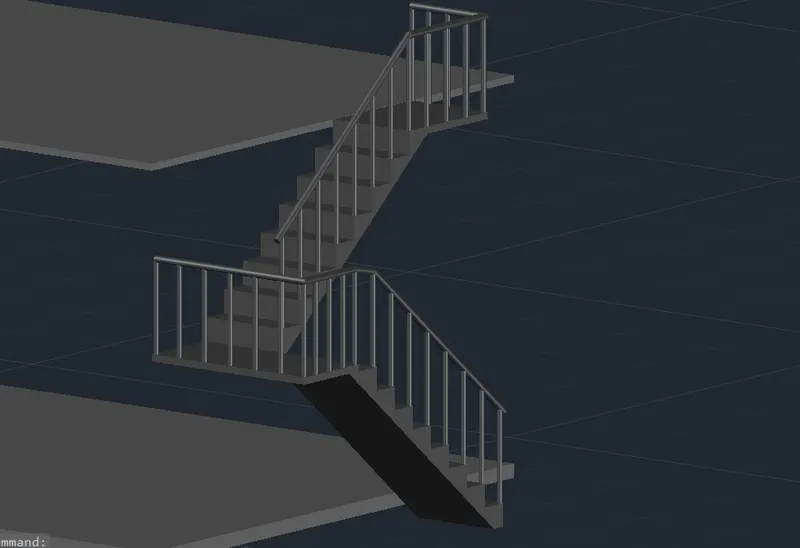
11. Rendering Part
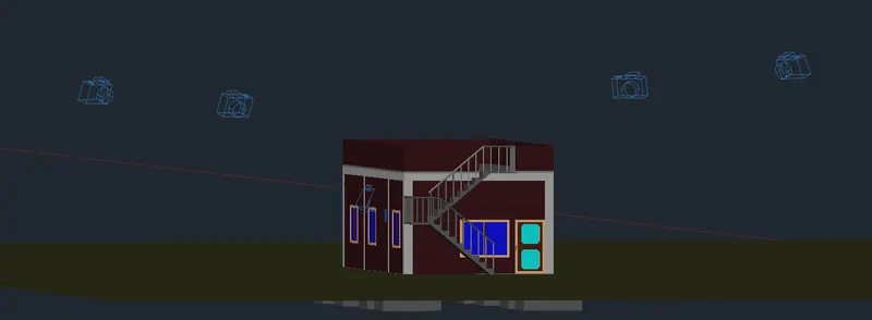
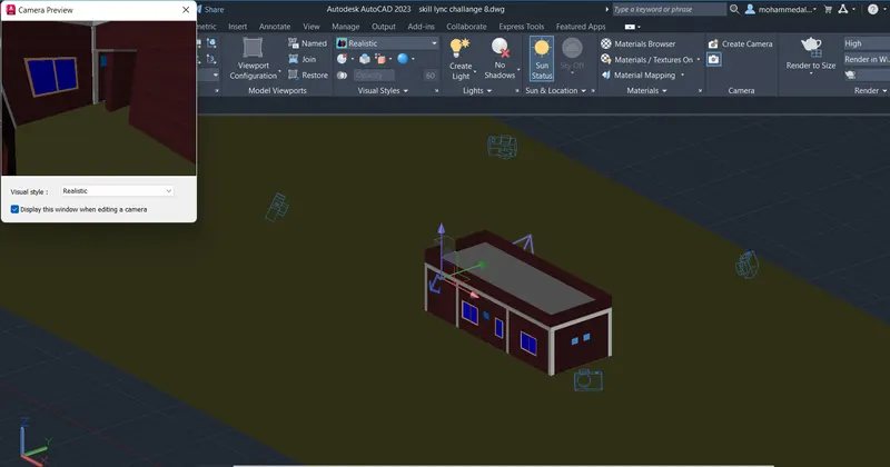
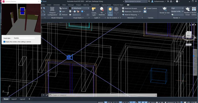
- Invork the camera command
- Setup the camera position
- Do the necessary adjustment like then lence, Name, View, size, etc
- Ater that save them
- With the help of render Environment and exposure change the exposure
- Turn on the Sun status
- Turn on the Shadow in order to make the shadow visible
- Use Material Browser to apply the material Surface to the element
- Use the material mapping option to Adjust the material surface
- Now Determine what option you want to render
- Select the render size
- determine Render accuracy
- Adjust its level
- Select the Quality of the render
- Then click on the render Icon
- Within a few minutes your product will be ready
- Save the Rendered picture
- Do the same for different View option
RESULT: