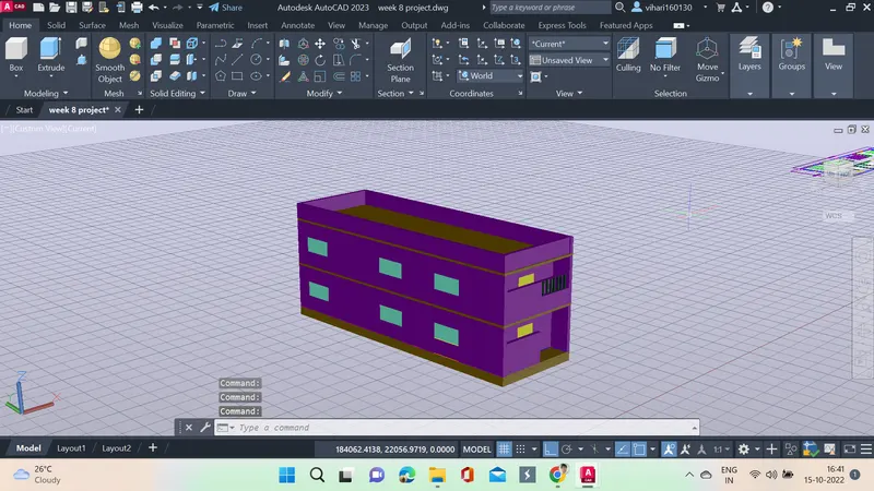
Project 2_Creating a 3D rendered model for a Residential Building in AutoCad
AIM: To create a 3 dimensional model of the residential building with a rendered view.
INTRODUCTION: Autocad is a software well designed for drawing 2D and 3D plans for the strutcure designs. 3d drawing is very effective in terms of visualizing the drawn plan, Extrude is the most important tool which we use to drag and create the plan into elevation, so that the results are seen clearly. Layers are used to given different colours so that identifying the elements like interior walls, exterior walls, windows, doors becomes easy.
Procedure:
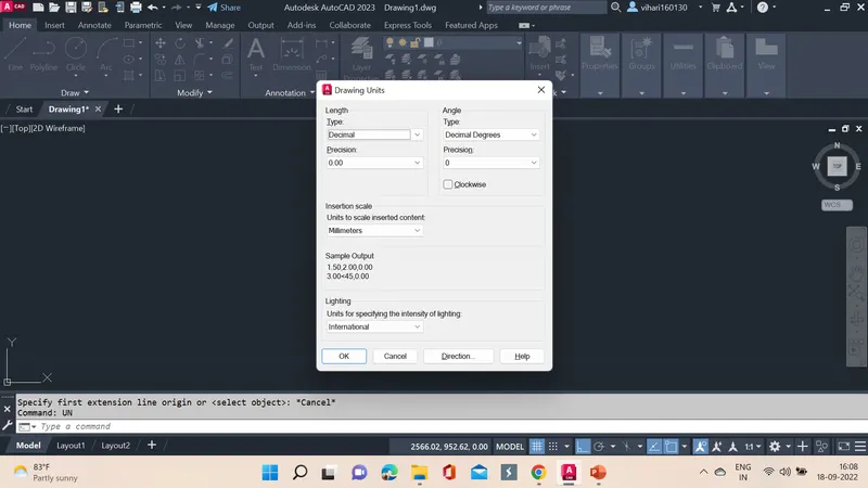
1. Open CAD software new file is created and then unit are specified to decimal.
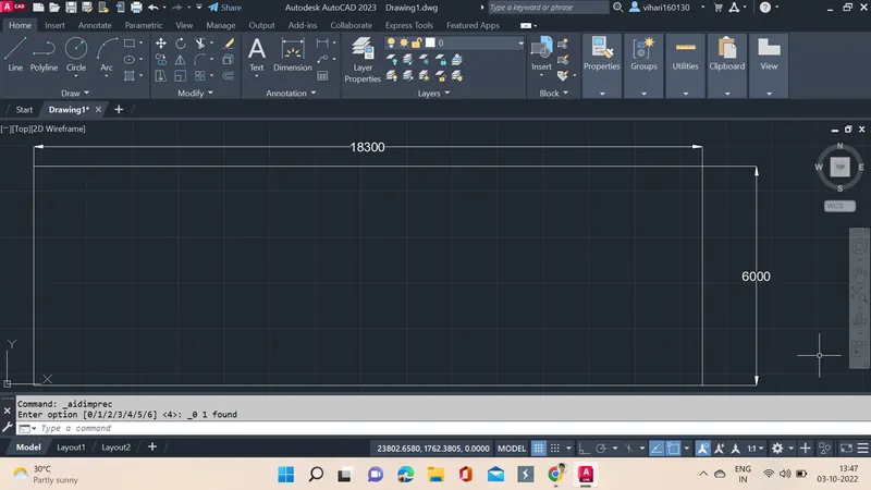
2. The next step is create the plot using the given specifications as 18.3m x 6m.
3. REC command is used and then dimensions are selected then length is given as 18300 and the width is given as 6000.
4. DIMLIN command is used and the dimensions are mentioned.
5. Architectural plan is made first using Layer command in order to specify the external walls and interna walls differently to identify quickly.
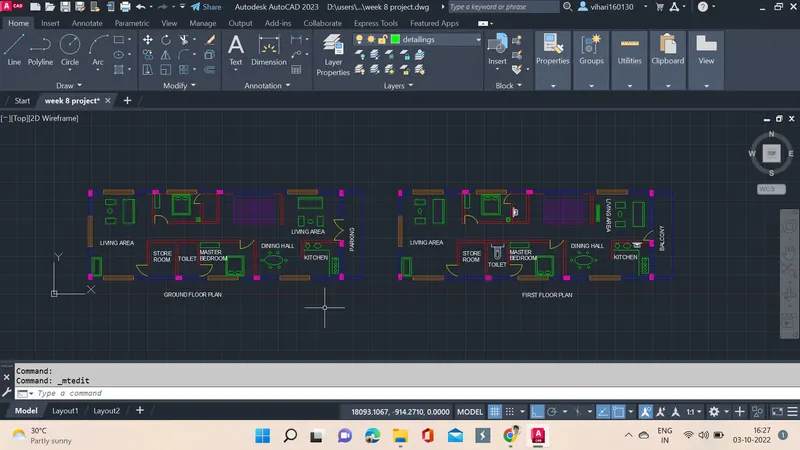
6. This plan consists of two floors ground floor, first floor with opening facing east according to the given plan.
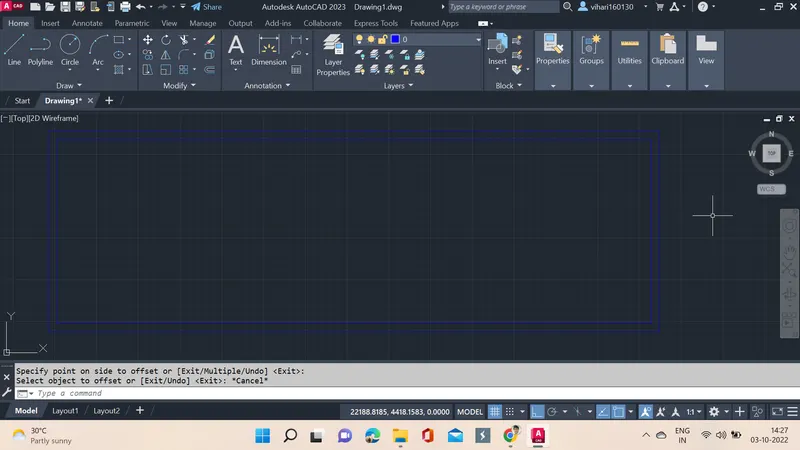
7. Layer is opened a colour is specified and external walls name is specified and then O offset command is used and then 250mm is drawn inside the present rectangle.
8. Layer is opened a colour is specified and internal walls name is specified, next the rooms are divided into bedroom, kitchen, dining, living room etc.
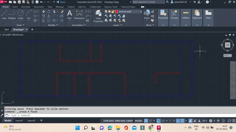
9. A layer is created a colour is specified and staircase is drawn for connecting ground and first floor.
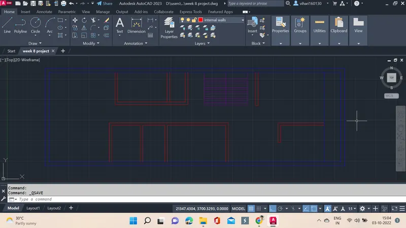
10. Now openings are made then doors are kept using anothher colour another layer.
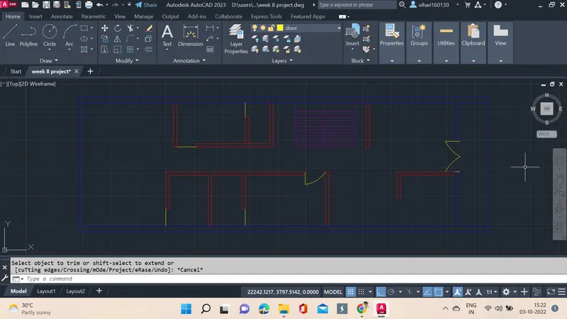
11. Now windows are drawn using another colour another layer.
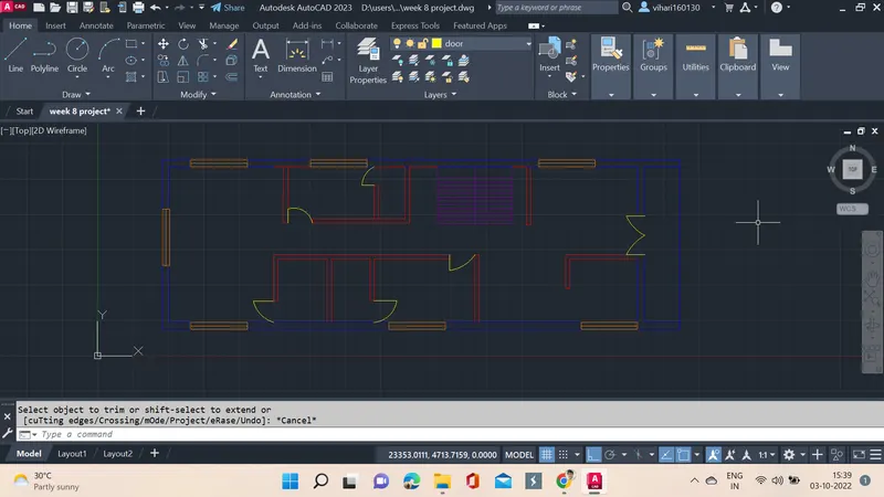
12. Some detailings like kitchen room is done, living room sofa is drawn.
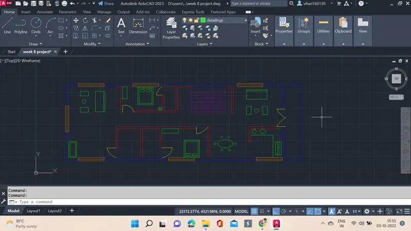
13. Columns are placed in the respective places.
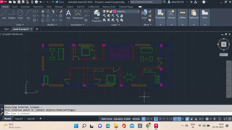
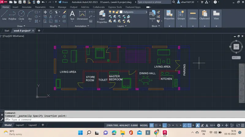
13. The MTEXT command is used to give texts and then ground floor is completed.
14. The process is almost the same for first floor plan so the steps are repeated and then the final first floor is as below.
15. Only change is that in place of parking balcony is drawn.
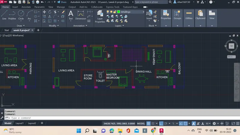
16. Architectural drawings are drawn for both floors.
17. Elevation is made for both floors using external walls layer itself.
18. L command is used to draw the elevation, first a point is specified and then a line is drawn using @6000,0.
19. next point is specified as @0, 600 and line is drawn, next point is specified as @-250,0 and a line is drawn.
20. next point is specified as @0,3060 and line is drawn, next point is specified as @-5500,0 and a line is drawn.
21. next point is specified as @0,3060 and line is drawn, next point is specified as @250,0 and a line is drawn.
22. next point is specified as @0, 1000 and line is drawn, next point is specified as @-6000,0 and a line is drawn.
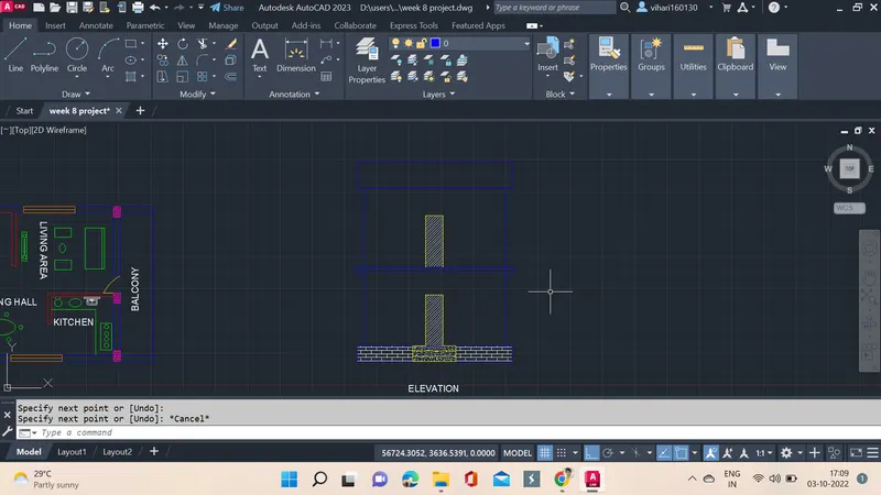
23. the missed lines are joined and elevation is completed.
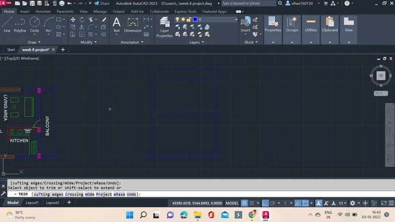
24. Small detailings are added and H hacthing is used hatch command is used.
25. Now 3D modeling is selected.
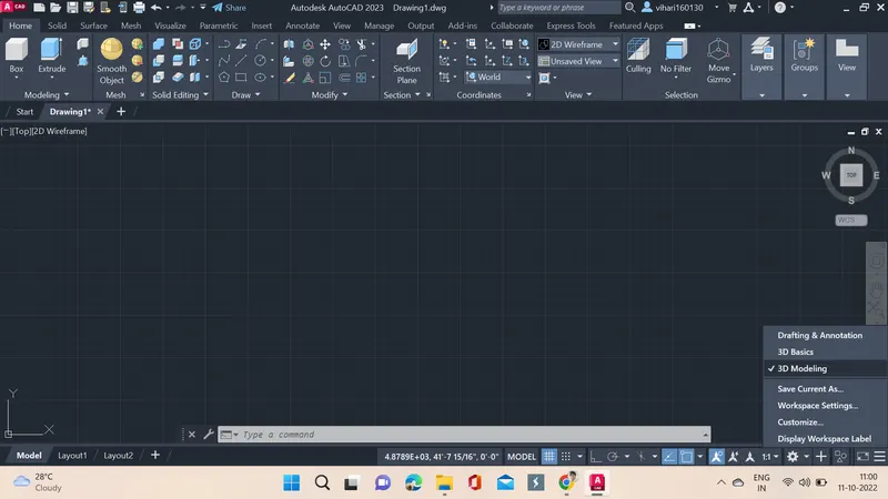
26. From visual style we select 2D wireframe.
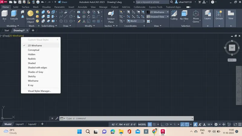
27. Southwest direction is selected from view.
28. BO command is used and boundaries are selected.
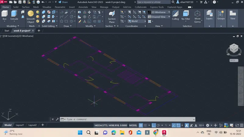
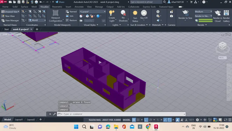
29. Extrude option is used to extrude the ground floor with a height of 2910.
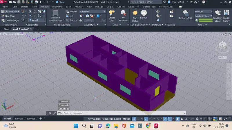
30. UNI command is used to combine the different parts into single unit.
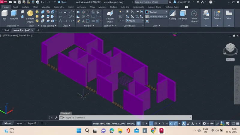
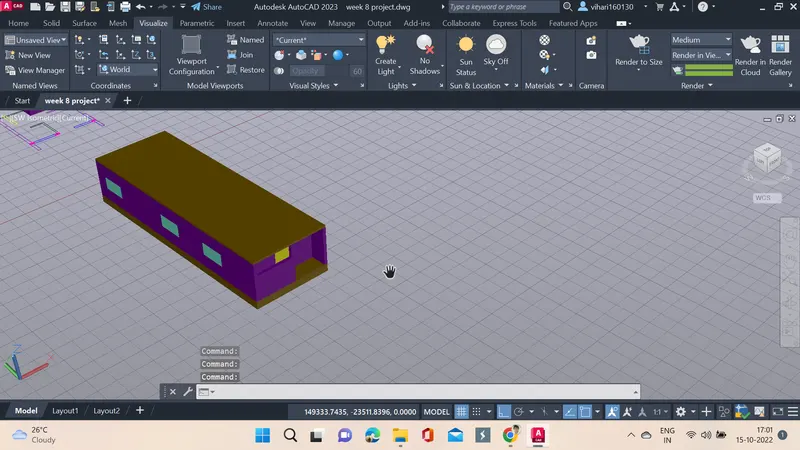
31. Doors and windows openings are created and then UNI command is used to combine all pieces into one unit.
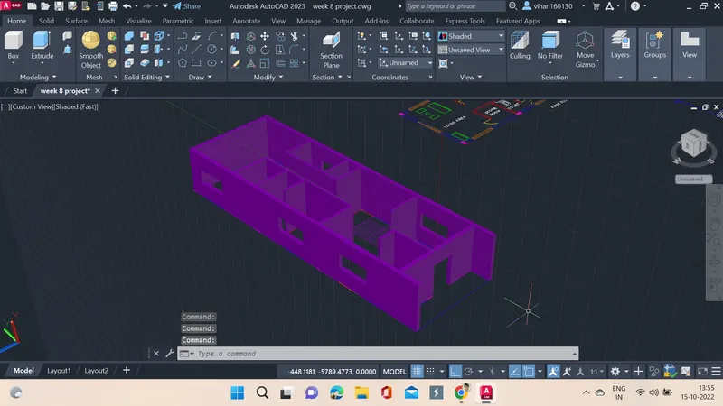
32. To create a plinth a rectangle is created using REC command and then extruding is done of -600.
33. Extruding is completed and then the groundfloor with plint looks like.
34. Windows and doors are created with forming rectangle and then extruding is done with 970 for window, and door is of height 1980.
35. Using REC command area is created and extruding the layer of 150 a layer is created.
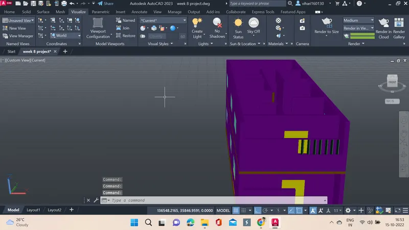
36. The process used in creating the ground floor is same for first floor either we can create or copy can be done if the outlines are same.
37. The balcony is prresent according to the design and rectangle is created and extruding is done for height of 1000.
38. C command is used with radius 75 and 7 cylinders are made by extruding 900.
39. Rectangle is created and extruding is done for height of 10.
40. Using REC command area is created and extruding the layer of 150 a layer is created.
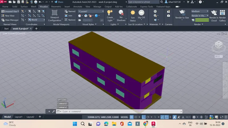
41. Using REC command full area is created and then boudaries are created using them top layer is created.
42. Parapet of 1000 is also created by extruding the rectangles and final building in 3D is completed.
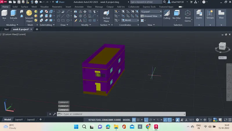
RESULT: Using autocad 3 dimensional model of the residential building with a rendered view is created.