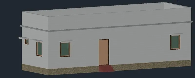
Project 2_Creating a 3D rendered model for a Residential Building in AutoCad
AIM:- To create a 3D model of the residential building with a rendered view.
PROCEDURE:-
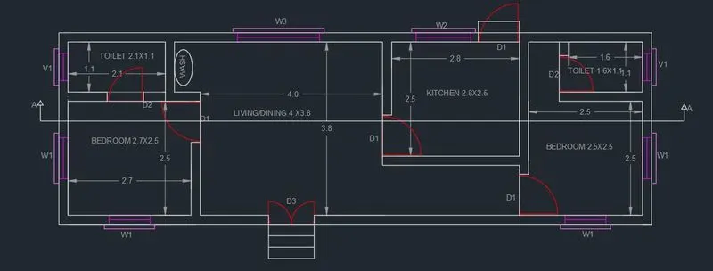
- drawing the floor plan
- open autocad and set the units to meters.
- using layer properties make the following layers, walls, windows, doors, texts nd dim,section, elevation, vport. give seperate colours to each of the layers.
- make the current layer as walls. draw rectangles representing each room and arrange them within the boundary of the plot drawn.
- the dimensions used are , bedroom -2.7x2.5m & 2.5x2.5m, kitchen -2.8x2.5m, bathroom -1.1x2.1m & 1.6x1.1m.
- arrange them in such a way that a good plan is created. after getting an idea of where each room is to be placed, draw the plan. make sure to offset a 0.2m wherever a wall is required.
- use trim command wherever necessary to trim off the unwanted lines at the corners etc.
- now make the current layer as windows. there are 4 types of windows of different dimensions, W1,W2,W3 &V1. make each type using rectangle and line command and make them into seperate blocks. insert windows as required.
- separate sunshades are made for each window. draw sunshade using line property. the sunshade starts 100mm away from the window ends.
- make the current layer as doors. there are 3 types of doors of different dimensions D1,D2 & D3. make each type of door using rectangle, line , circle and trim command. make them into a block. now by clicking on the block make D1 & D2 into a dynamic block such that they can be flipped. by clicking on the dynamic block properties, click on parameters and select th eflip parameter. then go to actions and click on the actions property.select the object and the required parameter. check if the flip property works and close the edit option.
- now place the doors whereve required.
- make the current layer as texts nd dim. using dimension property, dimension all the rooms and boundaries. using text option write down the names of the rooms , doors, windows etc.
- the floor plan of the building is done
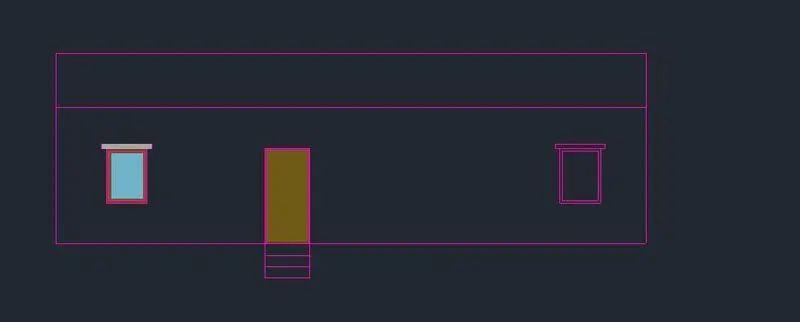
- drawing elevation of the floor plan
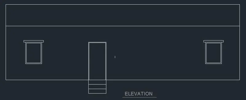
- to draw the elevation of the plan, the plan was copied the elevation was drawn below it.
- a horizontal line was drawn first and offseted to the height of the door, terrace floor height and the parapet height.
- construction line swere drawn to mark the position of the windows and the doors. using trom option the unwanted lines were erased.
- using offset option, detailings of the windows and doors were done. the sunshade was also drawn
- steps were drawn in the front.
- the elevation is now copied and placed on the right side of the firts floor plan drawing.
- drawing the 3D drawing of the floor plan
- open autocad and change the setting to 3D modelling mode. make sure the units are in m
- make a layer and name it walls, foundation, sunshade, concrete. assign different colours for each layer.
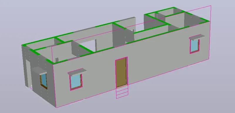
- make current layer as walls. first take the plan view and draw over the plan using pline excluding the doors and windows.
- make a region of the closed surface using region command.using extrude command, extrude the walls to 3m.
- extrude the windows to a height of 0.9m. now using ucs option, the top face of the extruded walls is selected.
- draw rectangles that represent doors and windows. make these rectangles into a region and extrude them below such that hollowed sections are created in place of doors and windows.
- make the following layers to make the window and doors. window frame, window mullion, window glass.
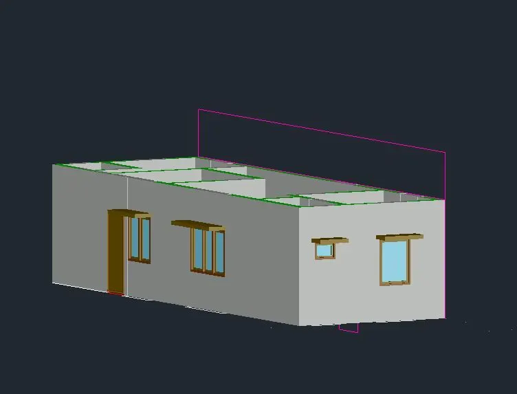
- now to draw the windows are doors. rotate the elevation of the drawing at an angle of 90 degree such that the elevation is in the front phase. using ucs option, place it on the front face and draw the windows and doors. copy this elevation to the side of the drawing to draw the windows and doors.
- there are 4 types of windows with different sizes. draw a rectangle outside the surface of size of the window in the elevation. offset the sides by 0.05m. trim off the unwanted lines to make 3 concentric rectangles. make the current layer as window frame and select the outer recatngle to make a region. then make the current layer as window mullion and make the inside rectangle as another region.
- now make the current layer as window frame and substract the inner region from the outer region.
- make the current layer into window mullion and select boundary option to make the boundary of the inner rectangle . now using region option make it into a region. make the current layer into window glass and then make it into a region.making the current layer as window mullion , substract the window glass region from the window mullion region.
- now making the current layer as window glass, make it into a region.
- check if all the substraction is done correctly by going into the shaded option.
- extrude the window frame by 0.09, window mullion by 0.075 and window glass by 0.05 inwards. now move the window mullion and window glass by 0.05 inwards and then the window glass by 0.025 inwards.
- select the whole window and make it into a group by using group option. now draw the sunshade . extrud eit to the front by 0.1m.
- select the window and the sunshade and move it into the hollow section reserved for the window.
- repeat the same for the different windows.
- similaryly do the same for the different doors.
- now to make the plinth layer. make a new layer called plinth and make it into a current layer. turn off the wall layer inorder to make the plinth layer. place the ucs on the plan. draw a rectangle from the one corner to the other of the floor plan. make it into a region. extrude it downwards to a height of 0.5m.
- turn on the layers. place the ucs on the top of the wall at 3m. draw a rectangle along th eplan boundary and offset it by 0.1m on all sides and make it into a region.extrude it by 0.15m. this make sthe roof top.
- now to draw the parapet. draw the boundary of the building and then offset it by 0.2m. make it into a region and extrude by 1.2m.
- now to make the stairs. place the ucs on the left side and draw the side section of the stair. draw the thread and rise and draw 3 steps. make it into a region and then extrude it by 1m.
- now to make the rendered view.
- to give material propertries, go to visualize option and select materials browser. select the category of the required material by clicking on the autodesk library.
- first select masonry. select masonry brick and click on 'add to document'. now select the bricks where masonry brcik is required and right click on masonry brick option and click on 'assign to selection'.
- similarly do the same for concrete, plinth.to do the sam efor the doors and windows, ungroup them an dthen select the required material property.
- using union option make the walls as one.
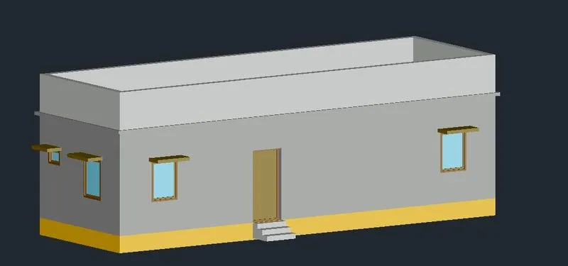
- to see the rendered materials, go to realistic option.
- the final figure is as shown below.