Project 2_Creating a 3D rendered model for a Residential Building in AutoCad
Aim & Intorduction: To create a 3 dimensional model of the residential building with a rendered view. 3d modelling is used. In layers layoff is used when needed to work easily. Extrude and solidedit commands are used to obtain the desired residential building. Use the commands 3drotate, union, subtract whever required in the drawing.
Procedure:
1. Draw the plan of the building as shown using the layers exterior wall, interior walls and windows
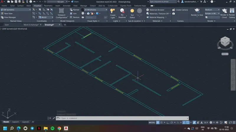
2. Using boundary command BO form the regions for all the walls
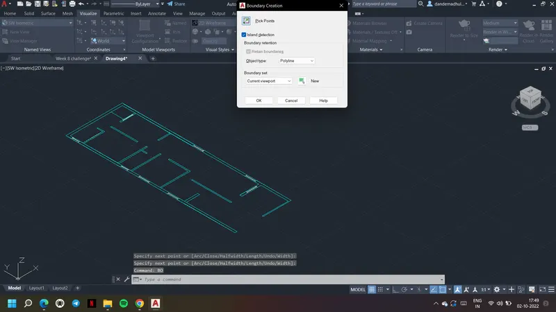
3. Select the formed regions and extrude them as shown
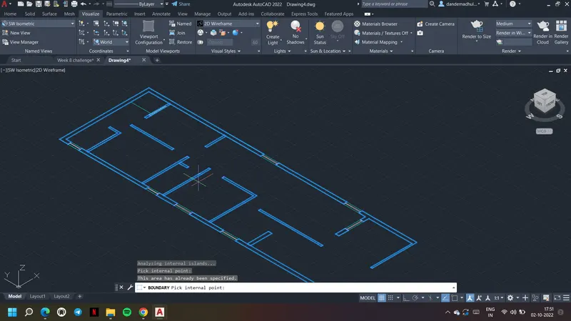
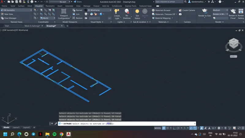
4. Choose the height of extrusion as 3000m
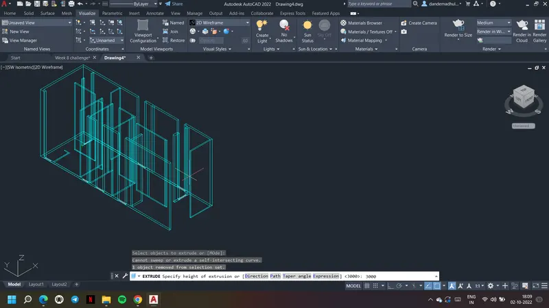
5. Go to conceptual view to form the shown drawing
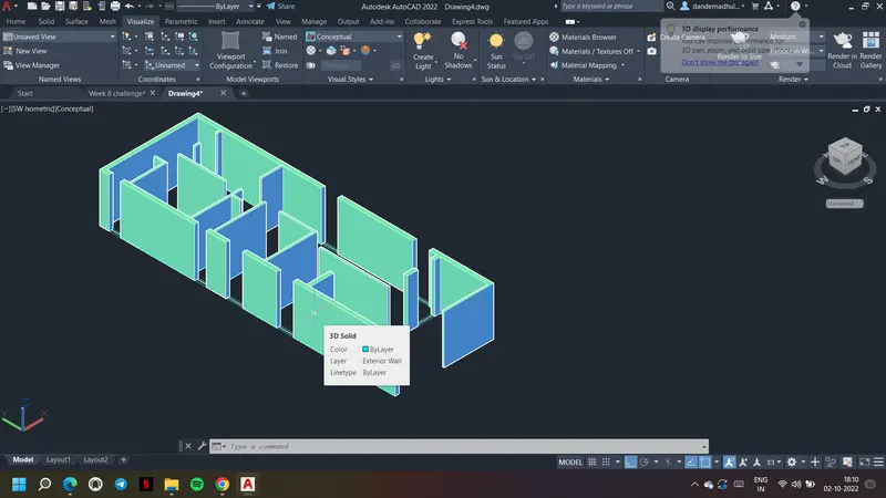
6. Now for windows draw the rectangle at bottom and extrude it to plinth level
7. Take plinth level as 600mm and extrude it as shown
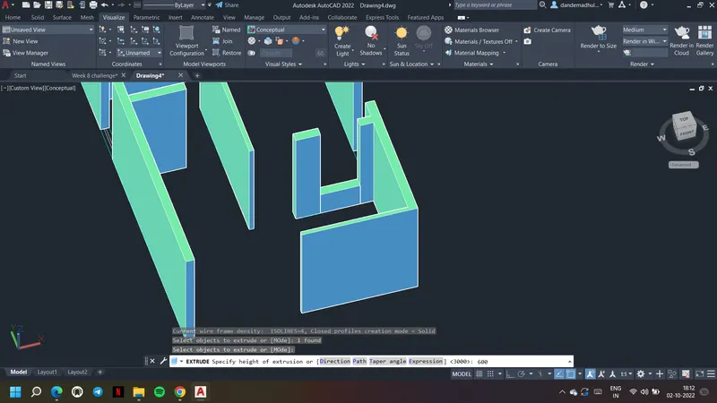
8. At top too draw the rectangle and extrude to lintel level i.e., 600mm
9. Draw rectangle wherever required using UCS command as shown
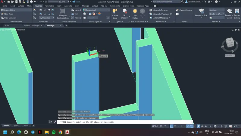
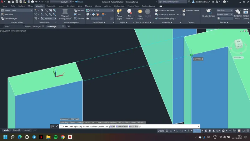
10. After forming rectangles union all the walls using Union command to form an entity
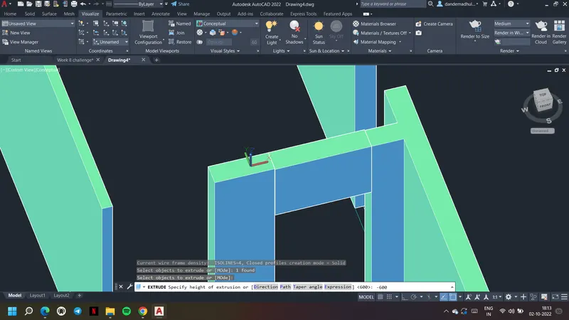
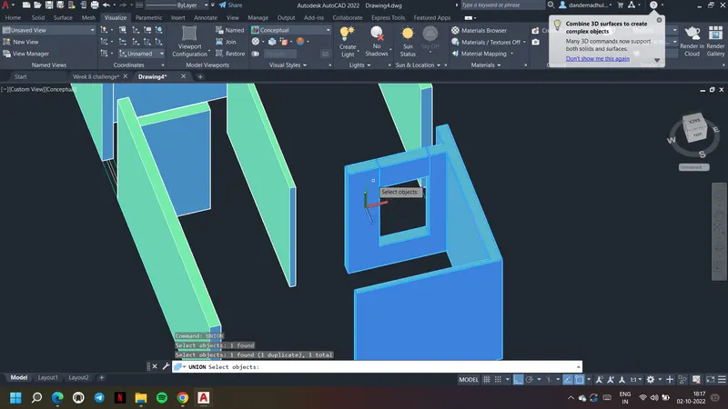
11. Draw the rectangles for all other windows too forming the same process
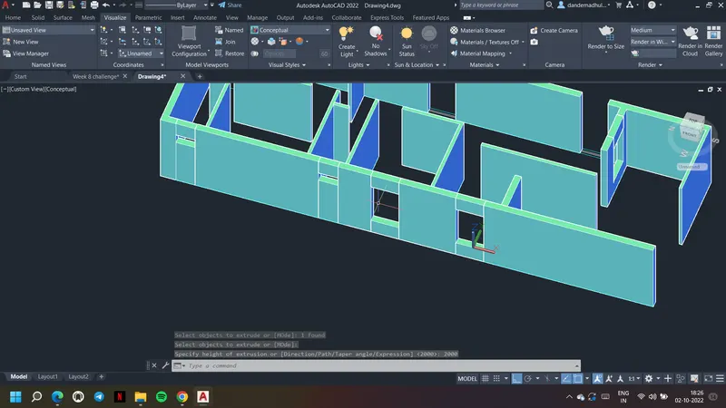
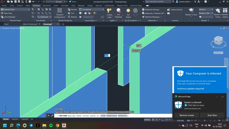
12. Union all the drawn elements using union command
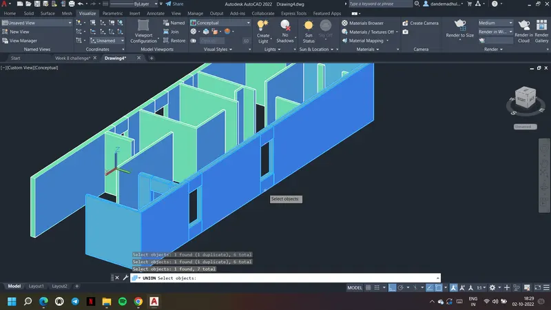
13. For balcony draw the rectangle on the wall as shown
14. Go to wireframe view, using solidedit imprint option form the surface for the drawn rectangle
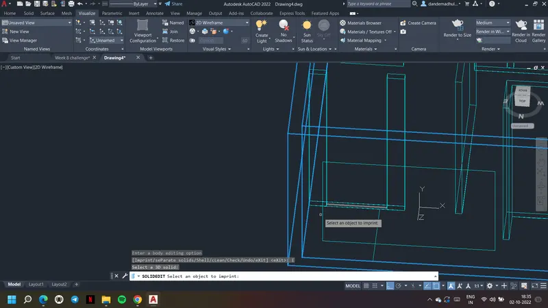
15. Using offset ot extrude option in solidedit form the opening as shown
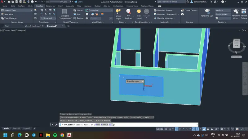
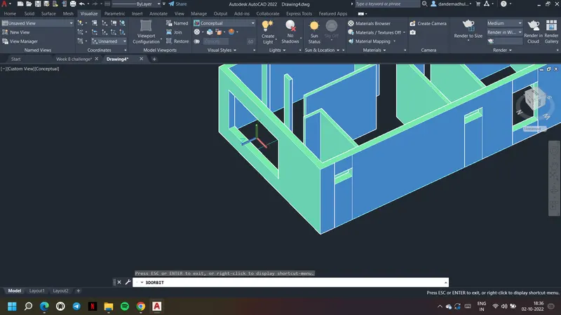
16. Draw the winodw opening for kitchen too and union them
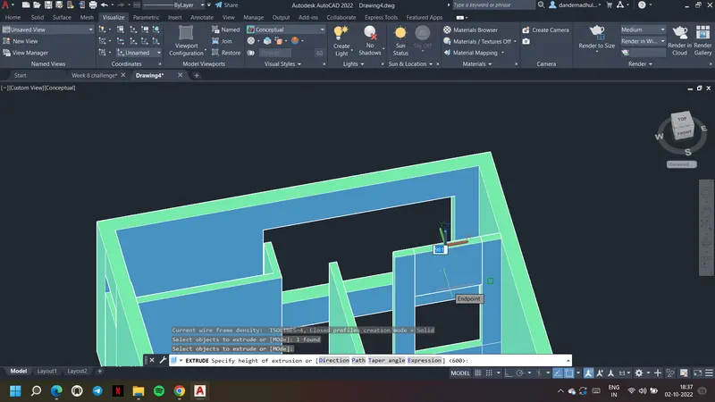
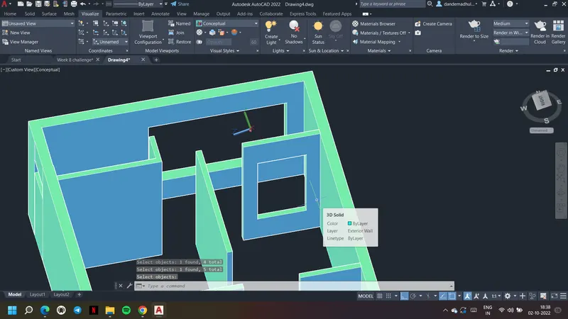
17 Rotate the elevation using 3drotate command and form the windows and doors
18. Window frame, window mullion and glass layers are formed and assigned to window as shown
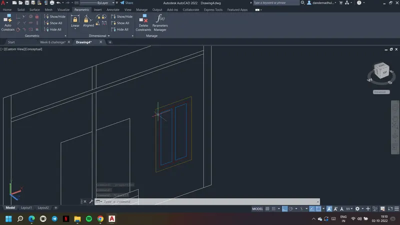
19. Using extrude command extrude the glasss to -12mm, mullion to -30mm and frame to -75mm respectively
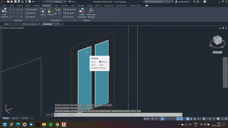
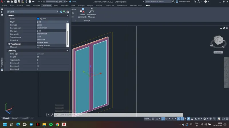
20. To separate window frame from mullion use the subtract command and subtract it from window mullion
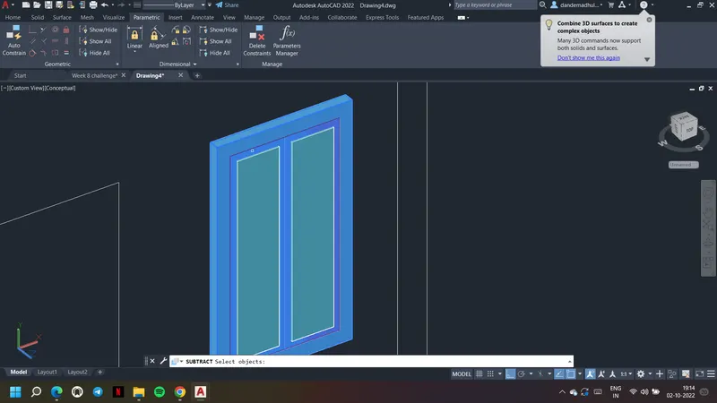
21. Required window is formed as shown
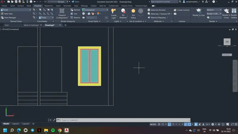
22. Copy the windoe and [aste in the model.
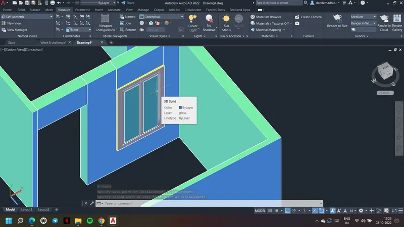
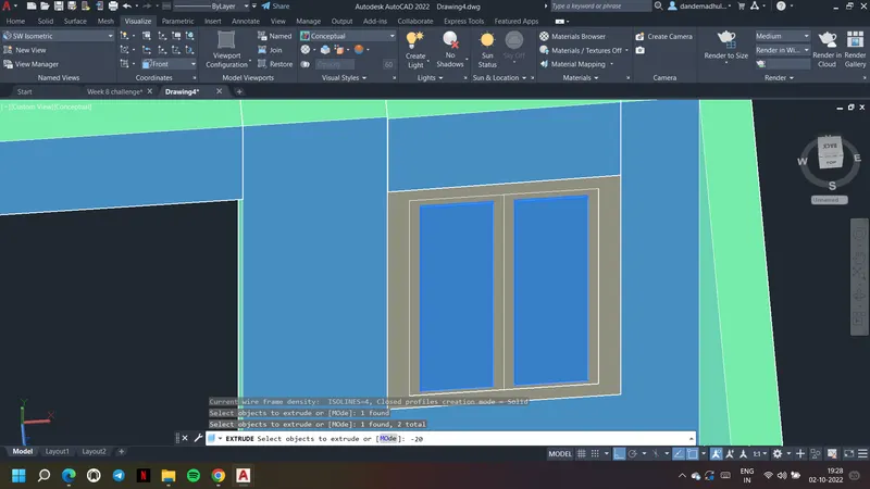
23. Move the glass 20mm and mullion 15mm backwards respectively from frame using move command
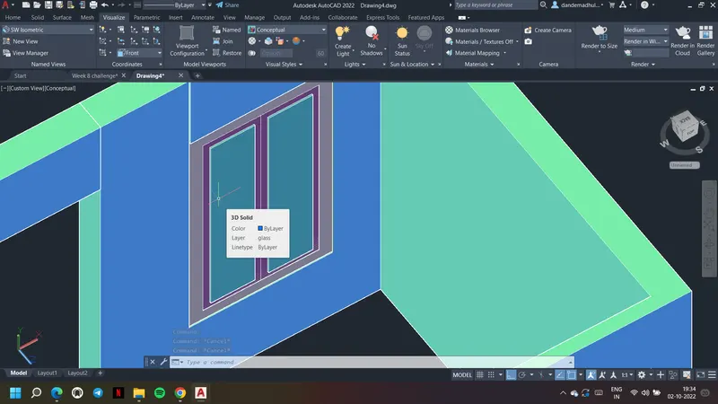
24. Rotate the window using 3drotate and place it at other sides of the building too
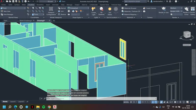
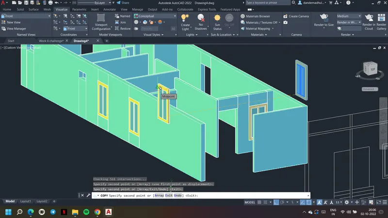
25. Similarly form door frame and door panel and place in the model.
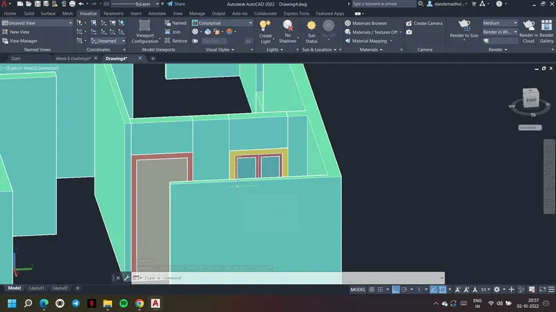
26. Extrude door frame to -75mm and panel to -30mm. While placing move it backwards 100mm
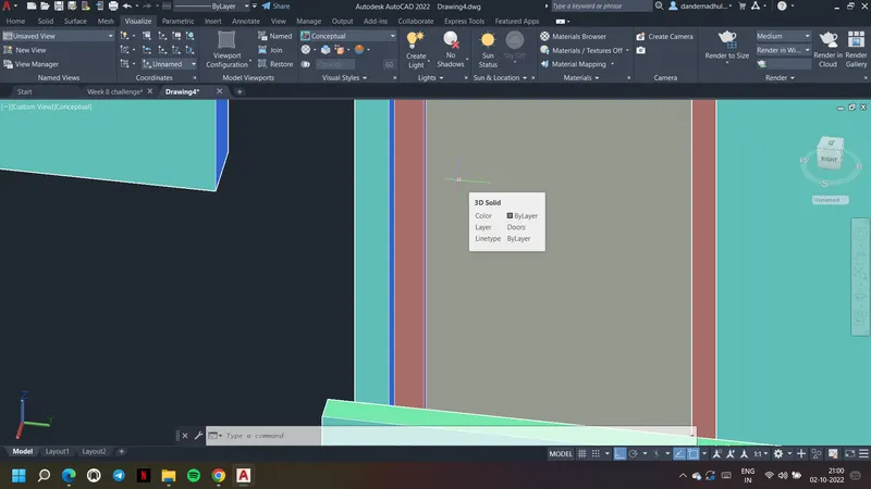
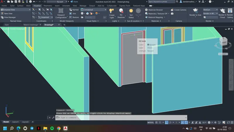
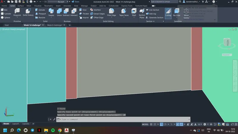
27. Rotate door using 3drotate and place it wherver required.
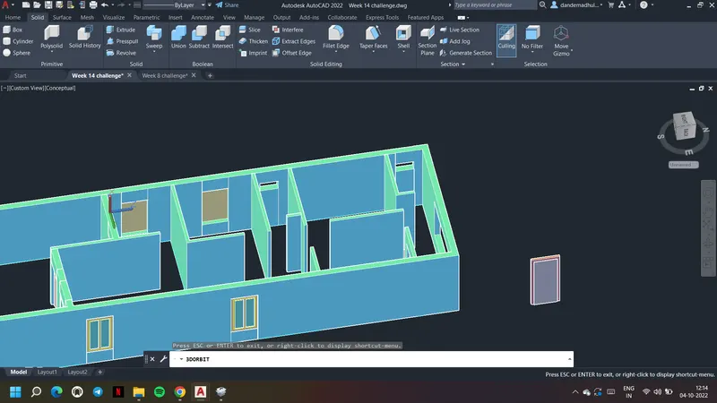
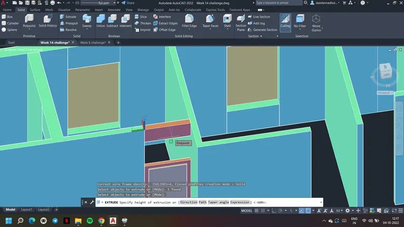
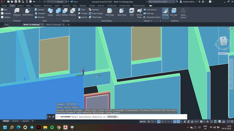
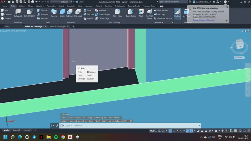
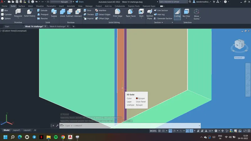
28. Opne the bottom view and draw a rectangle to create the floor
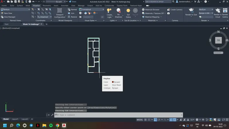
29. Create the floor layer first and off the layers to form the floor as shown
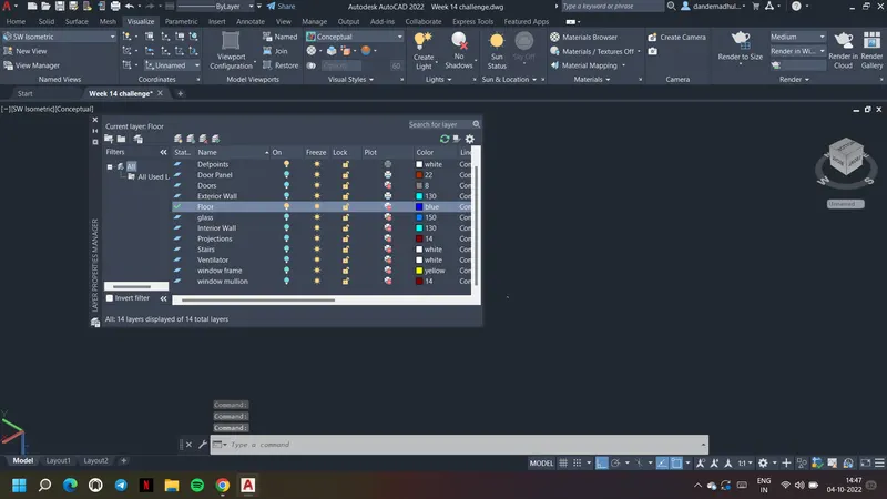
30. Extrude the rectangle to 600mm to form the floor as shown
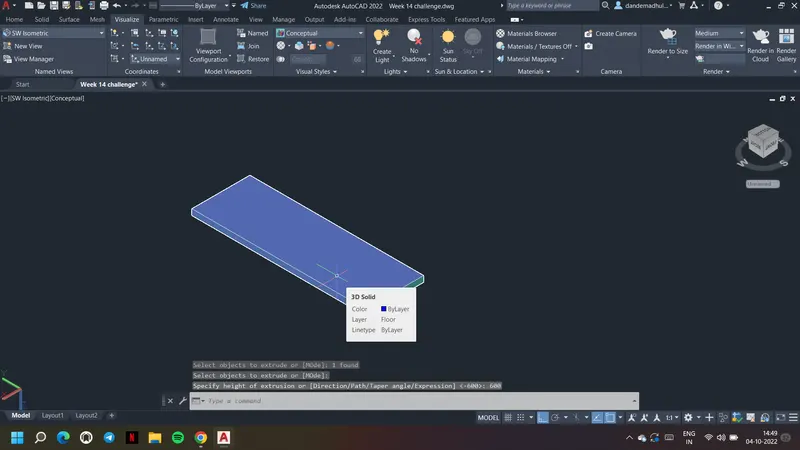
31. Using copy face form solidedit. copy the top surface of floor
32. Place it aside and explode it as shown
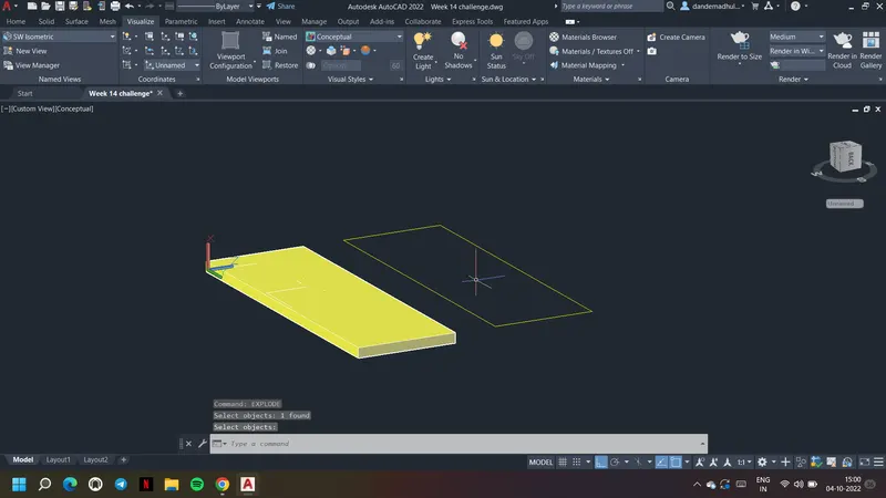
33. Draw the desired shape to form the wall clad at end of the rectangle
34. Using join comamnd join the below shown three faces
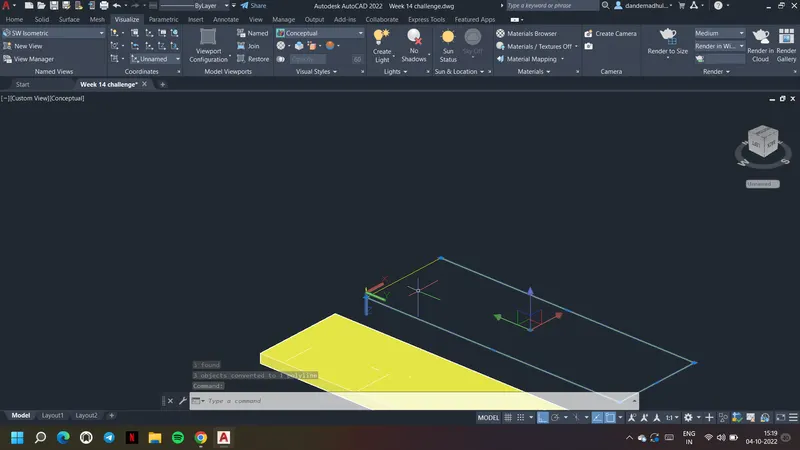
35. Using BO form a region and extrude it in the path shown
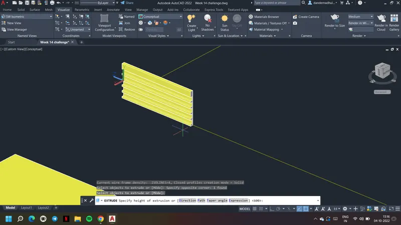
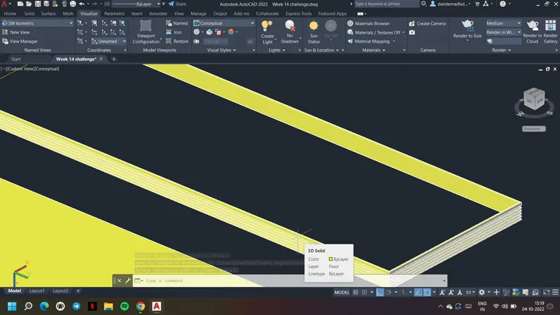
36. If required assign wall clad to floor layer
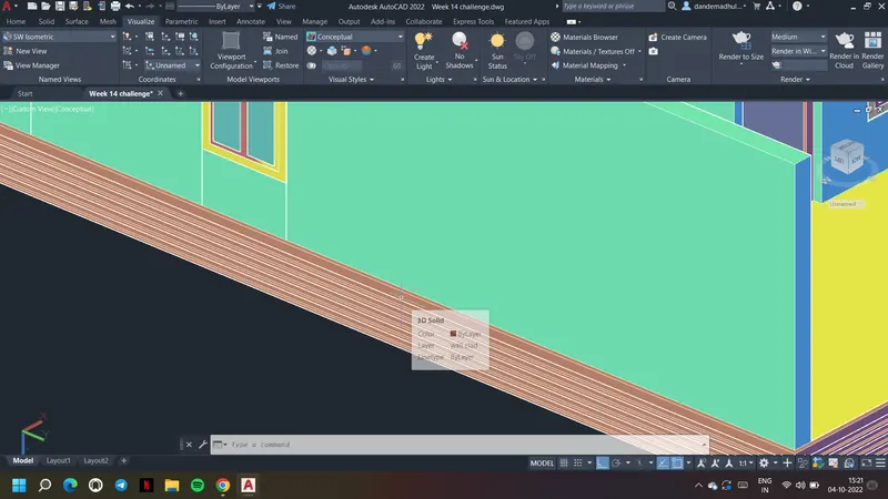
37. Draw a rectangle and extrude it at front as shown
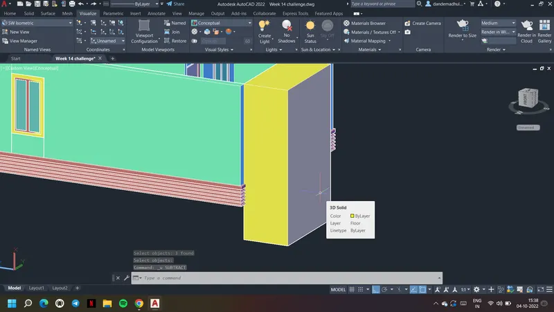
38. Now use subtract comamnd and subtract it to form opening at the front
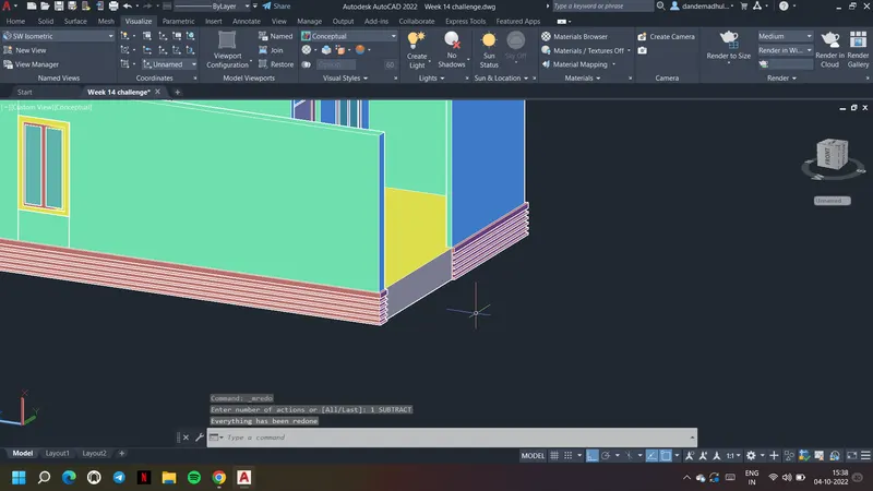
39. For the balcony also draw the window frame and glass
40. Draw rectangle, region them and extrude if needed
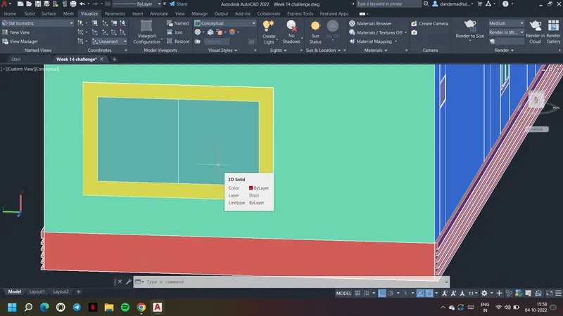
41. Create the slab layer and draw a rectangle as shown from interior walls
42. Extrude it to 150mm to form the slab
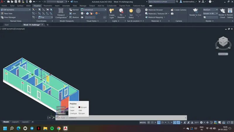
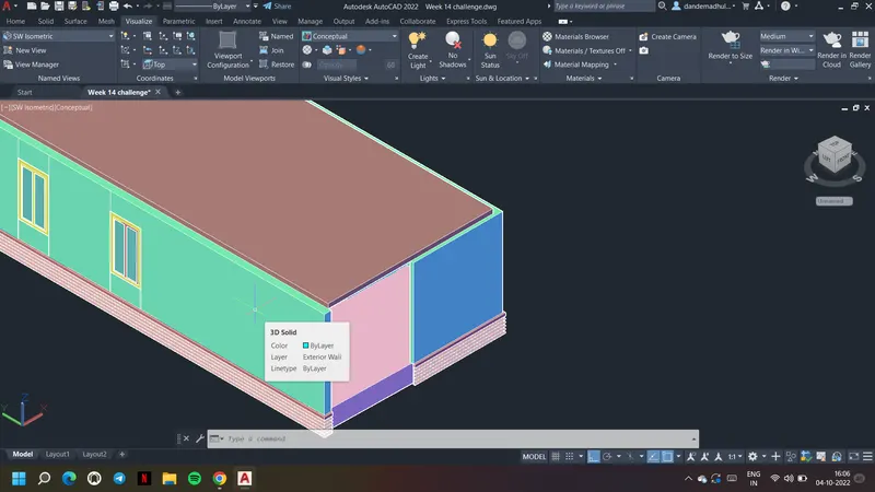
43. Copy all the elements and place it on slab to form the first floor as shown
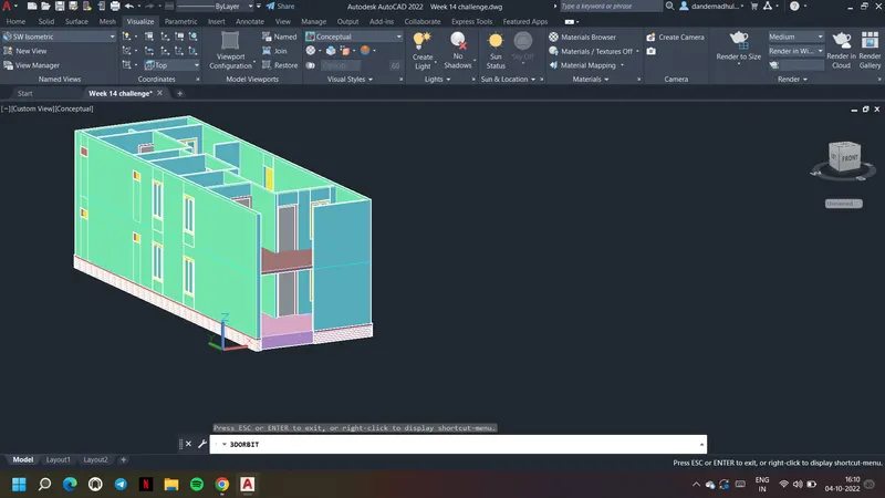
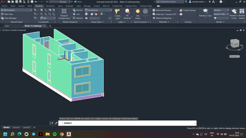
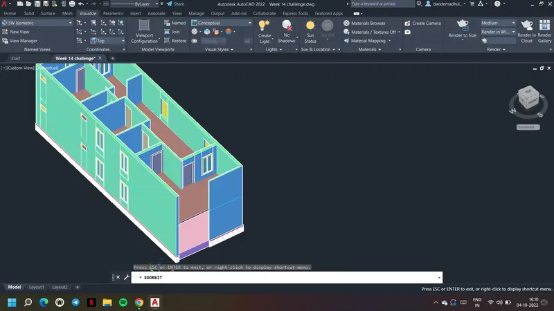
44. Similarly draw slab of 150mm above first floor too
45. Now for parapet wall. Draw the rectangle ot top of building
46. Move the drawn rectangle and offset it to 230mm and form region
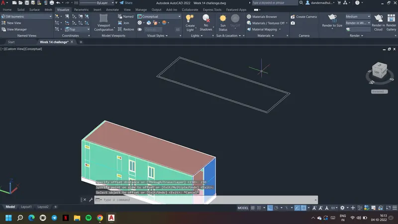
47. After forming region extrude it to 900mm
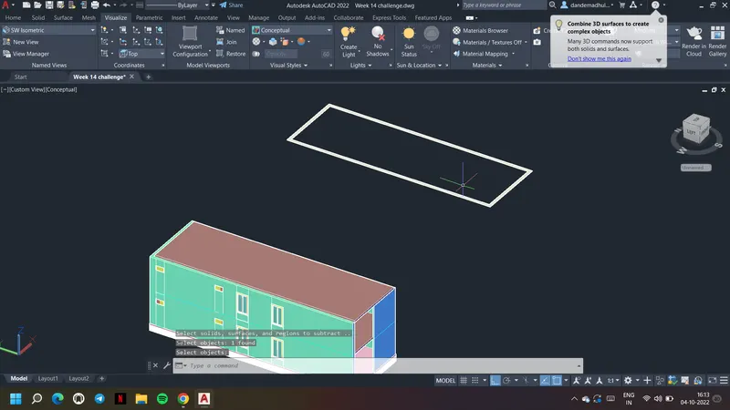
47. Off the layer of slab to view all the floors.
47. Using union comamnd union all the drawn floors and parapet wall
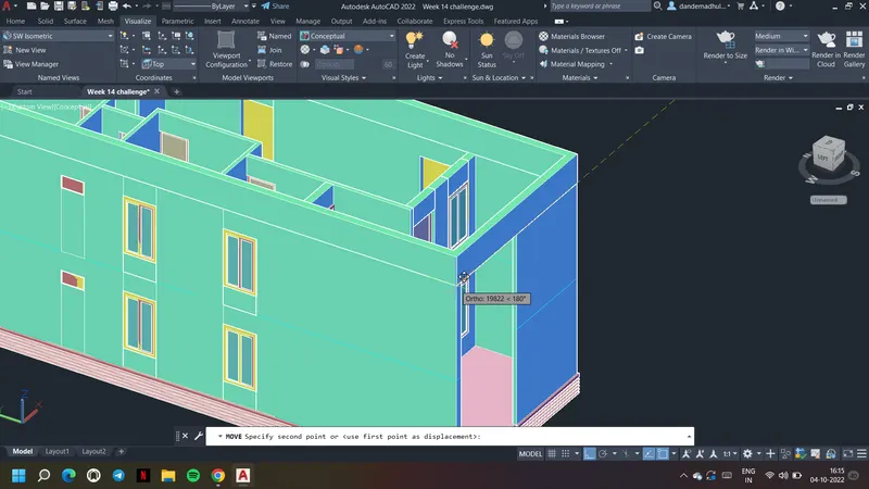
48. Now stairs layer is c
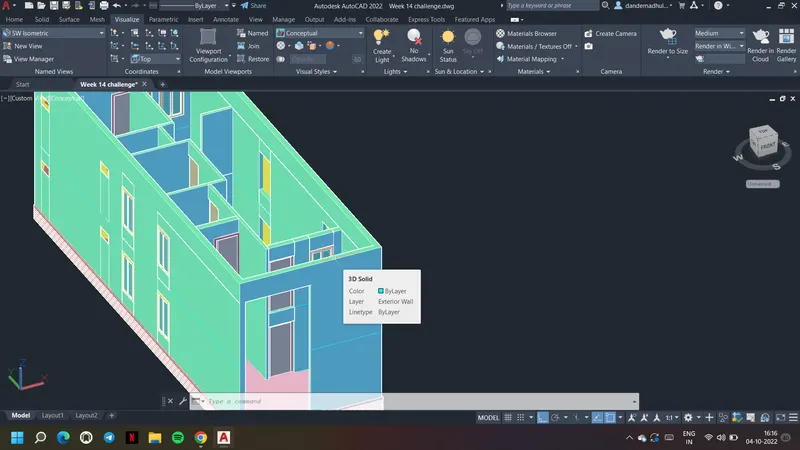
48. Now stairs layer is created and the below shown ramp is drawn using extrude command
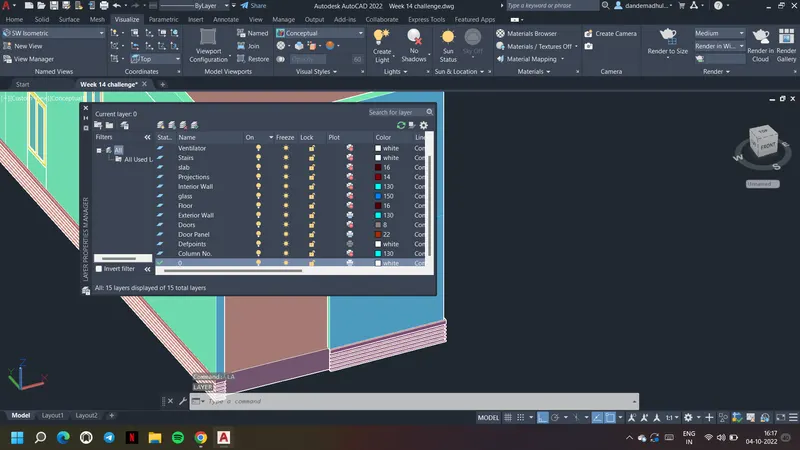
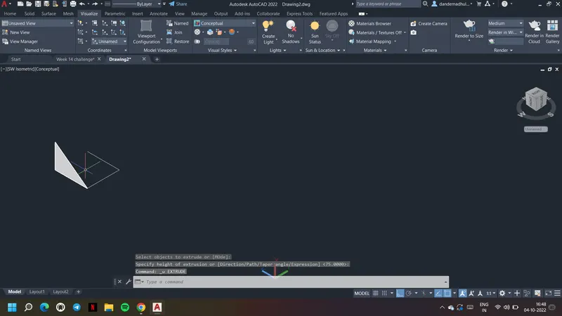
49. Stairs are also drawn
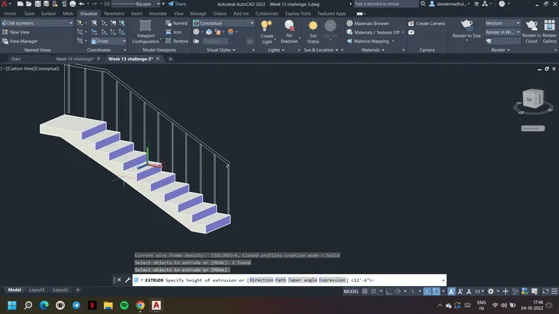
50. Use 3drotate, copy and paste options to paste the ramp and stairs in the drawing sheet
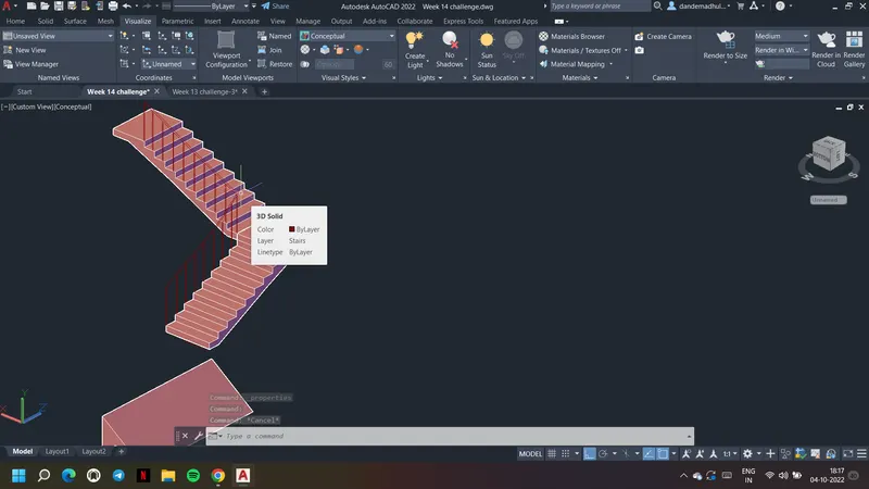
51. Off all the layers except stairs and draw the rectangle as shown.
52. Region is formed to extrude it and it is extruded till the terrace
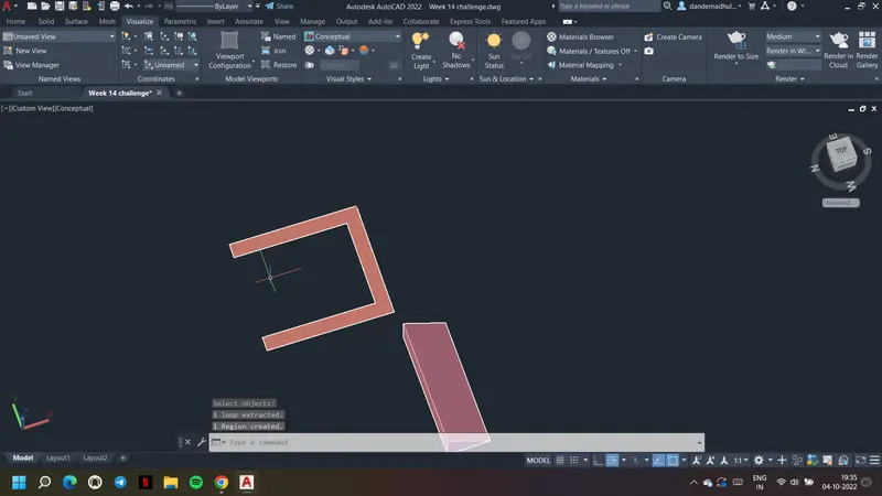
53. IThe lift is formed as shown, can also place the stairs in place of lift
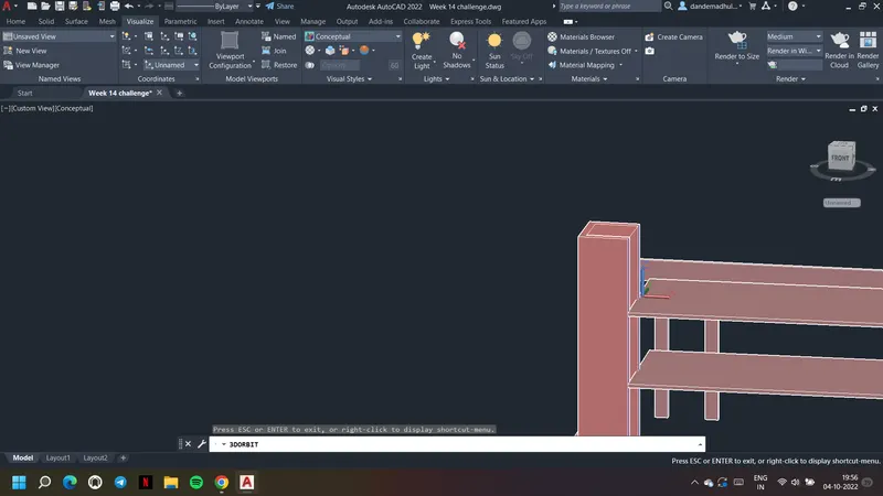
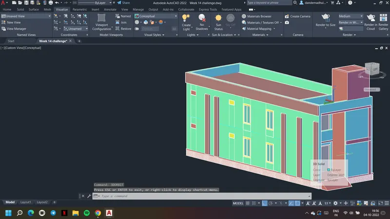
54. On all the layers to form the complete residential building
55. Draw a circle and extrude it to form the shown cylinder
56. It is used to place the camera
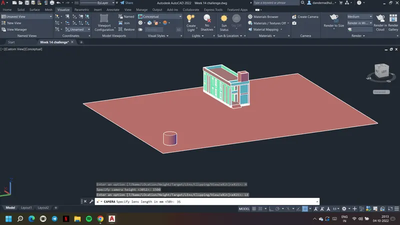
56. Give command Cam and create a camera and place at the requested place as shown
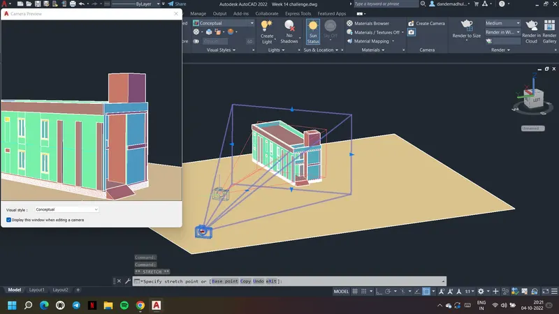
57. Deleet the drawn cylinder as not requried anymore
58. Can see the visuals from the camera as shown. Below shown is conceptual view
59. Go to shadow and realistic view as required
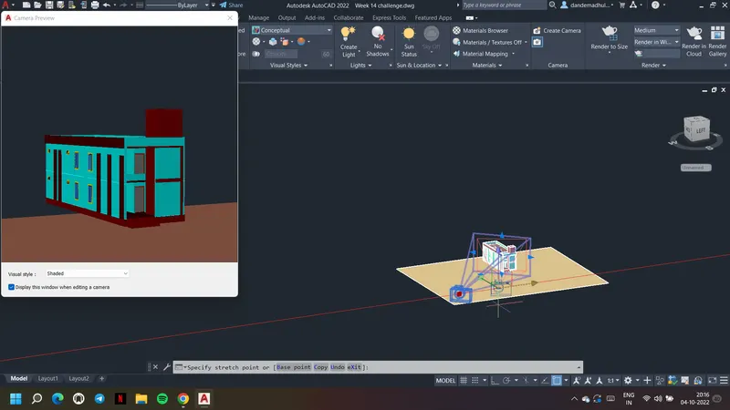
60. Set the sun status and also create the distant light from create light option
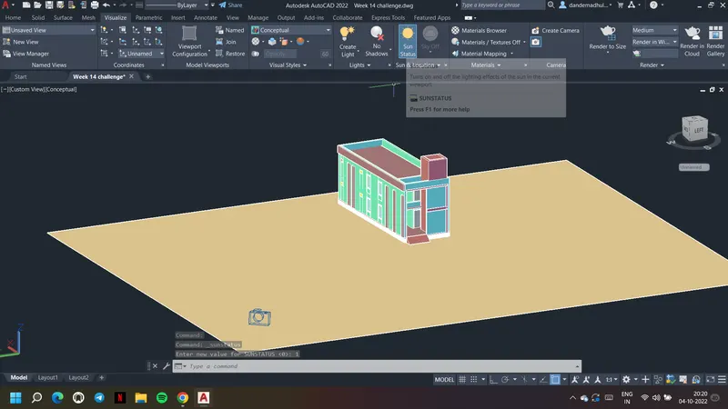
61. Create the camera1 view as shown by using view manager
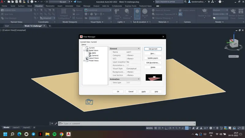
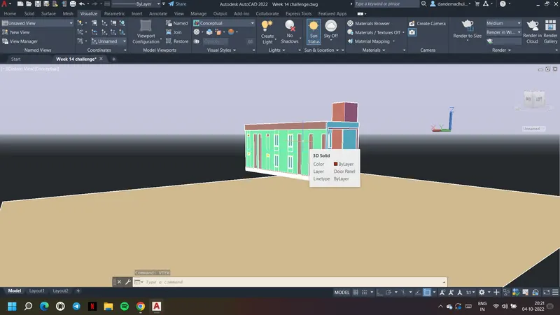
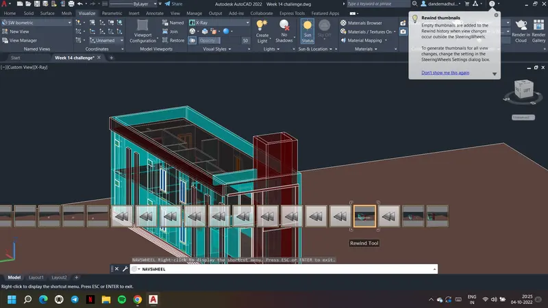
62. Go to Navswheel command and use it to zoom in and move inside the building
63. Go to material browser, choose the materials and select item from drawing and assign the material to it
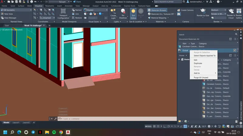
64. Here to ramp and wall clad the materials are assigned
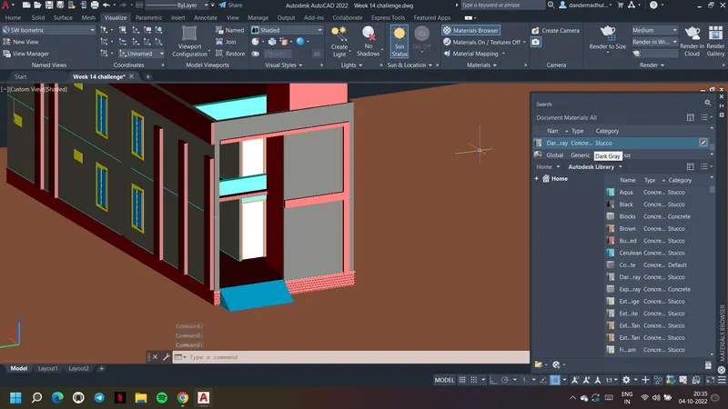
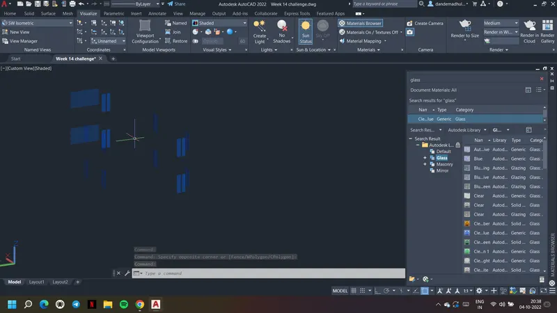
65. Off all the layers and for the glass assign the glass material as shown
66. Move the cam1 and create the other camera and second view as shown
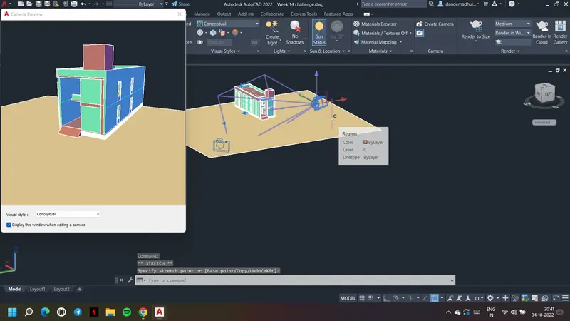
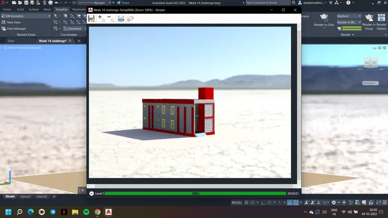
67. Go to rendering and set the options and by giving RR command render the residential building
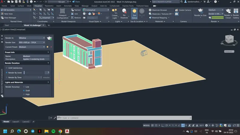
68. Following are the rendered view of the drawn residential building
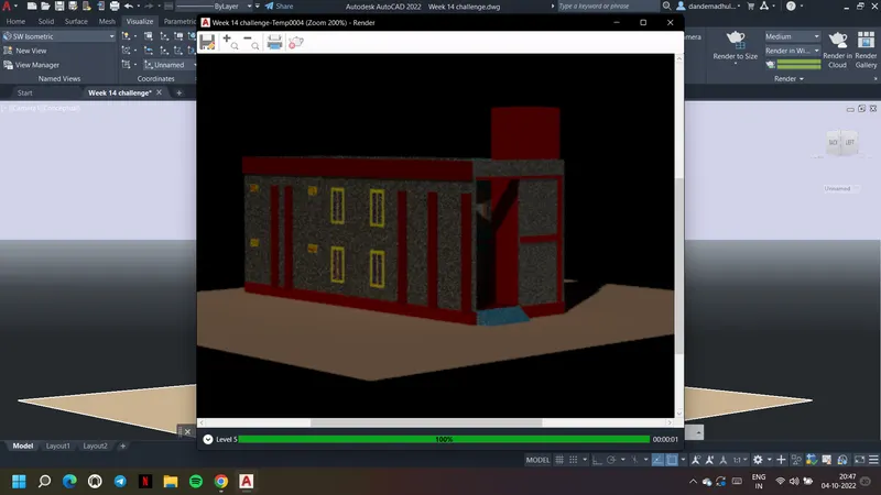
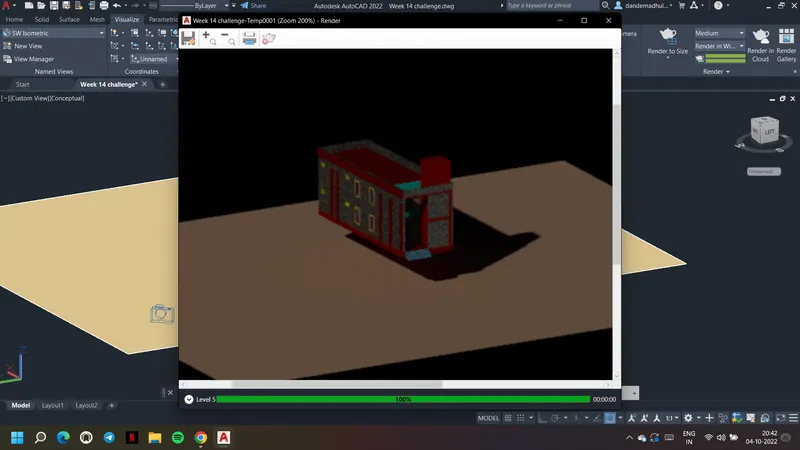
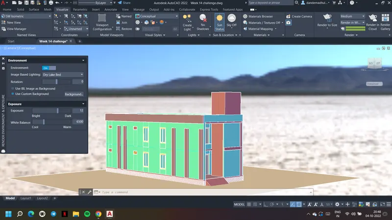
69. Go to render environment and exposure and set the background as desired
70. Go to RR command and render it as shown to form the below rendered view
Result:
3 dimensional model of the residential building with a rendered view
Rendered views of the drawn residential building