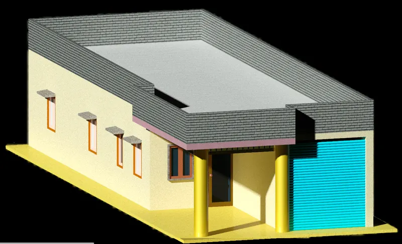
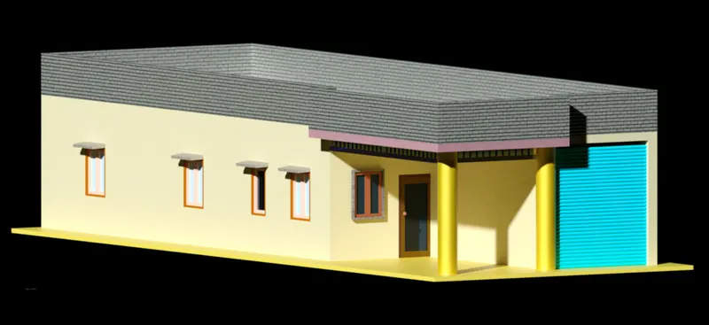
Project 2_Creating a 3D rendered model for a Residential Building in AutoCad
AIM: - To Create a 3D rendered model for a Residential Building in AutoCad
INTRODUCTION: - The plan is created using various tools in Autocad like rectangle, polylines, and circle arc modification tools like copy, move, offset, mirror, trim, and fillet, etc. The 3D Isometric View of the building with plan and elevation is drawn using proper 3D tools, primarily using the Line tool and after sketching, the dimensions and text are provided. The procedure of drawing is explained in detail with diagrams of each step and the final result is given.
PROCEDURE: -
Before we start the drawings we need to set up the drawing as Imperial Template and the units into Engineering Units.
Following are the steps in order to set up the drawing as Imperial Template and the units into Engineering Units.
- Go to Application Menu or click CTRL + N (New)
- Click on New from the Application Menu
- A popup menu appears, click on the first tab known as Start from Scratch > Select Imperial
- Now click on the third tab known as Use a Wizard > Go to Advance setup > A Dialog box appears > Select the unit of measurement as Engineering > Press Next > select Angle as Decimal Degrees > Press Next > Select Angle Measure > Press Next > Select Angle Direction > Press Next > Select Area > Click Finish
- Set the page limit by entering Limits in the command tab. The lower left corner is specified as 0'-0.0" and the upper right corner is specified as 100',100'.
- In the Drawing Units dialog box, select 'Engineering' in Type; ' 0'-0.0" ' in Precision; and 'Inches' in Insertion scale.
- Click OK
- Now we are all set to go.
Now,
- Draw a rough diagram of length 60' X 20', for simply imagining what to draw.
- Complete the box by closing the command.
- Take offset of 10" and do all round offset.
- Divide the 60' line into 4 parts.
Now,
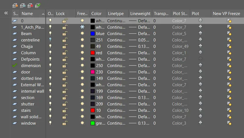
- Take some layer.
- Type LA or layer, a dialogue box appears.
- Select the following layers.
Now,
- Give the column of Dimension 10" X 12".
- Also provide circular colums of diameter 10" for aesthetic and structural loading at the fornt face.
- Give the beams of size 15" X 10".
- External wall is given as 10".
- Give the internal wall as 5".
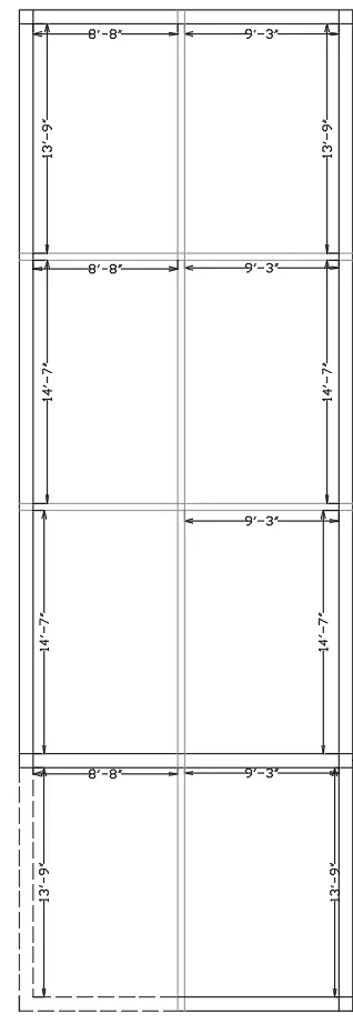
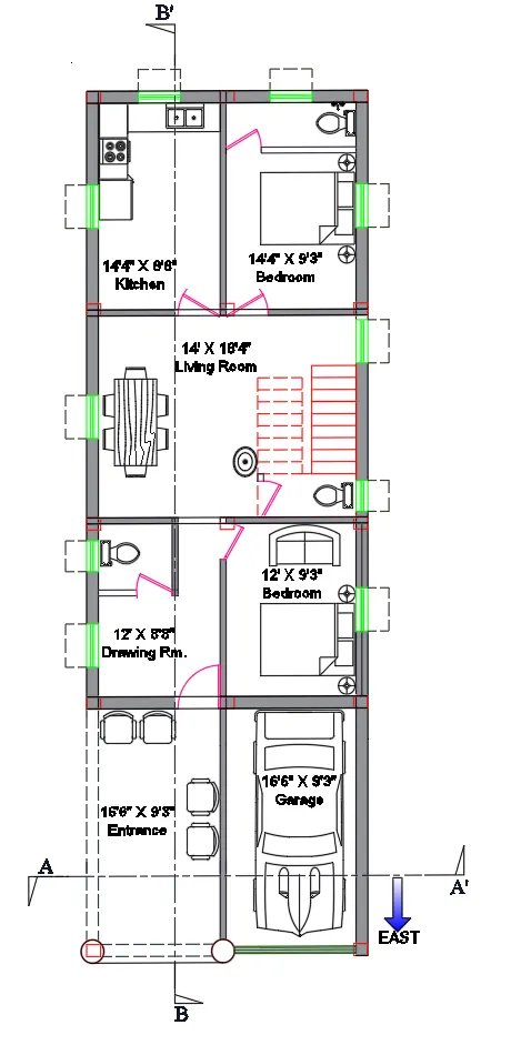
- Now give the dimension of each room, so that the area of the room is estimated.
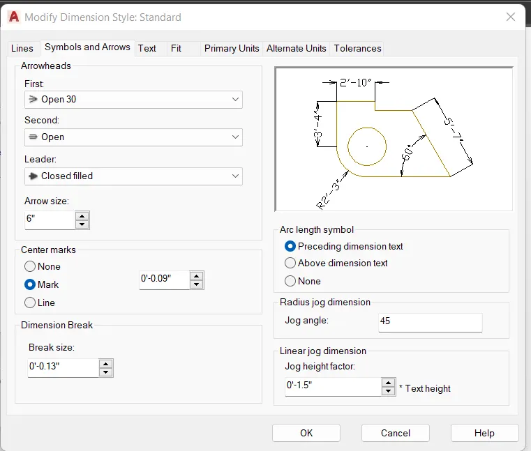
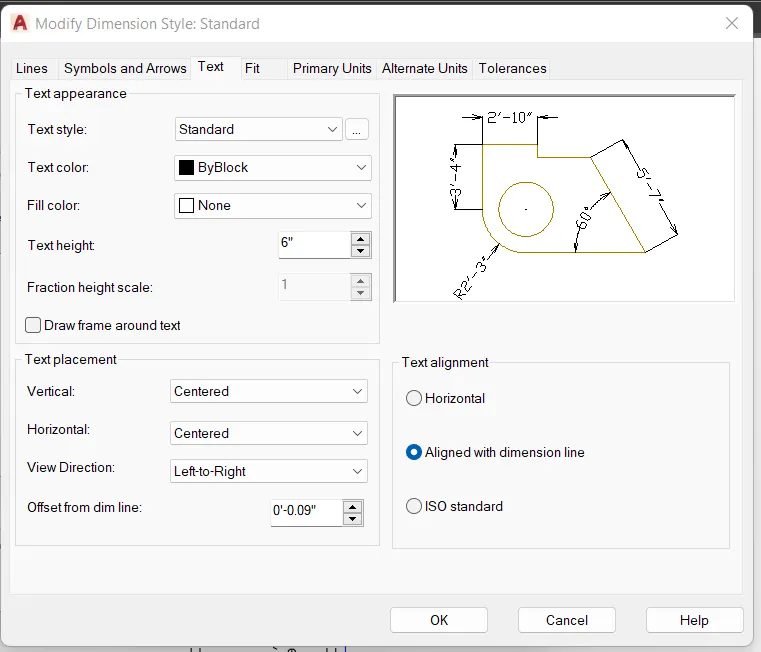
- Type D of dst or dimension in the command box.
- A dailogue box appears select the arrow as open arrow and size as 6".
- Go to Text and take the size of teh texts as 6".
- Press Ok and then close it
Now,
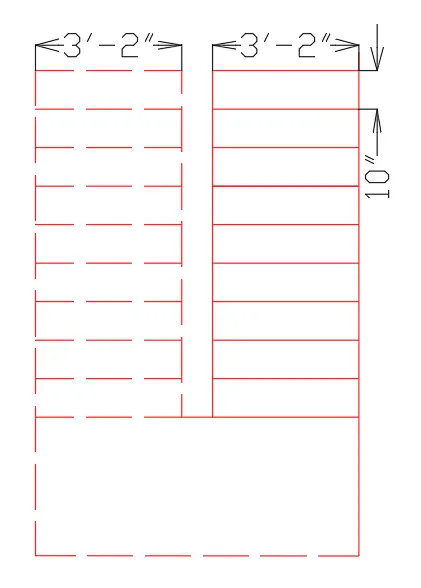
- Let us draw the stairs.
- Take the riser as 6".
- Take the tread as 10".
- Take the width of stairs as 38".
Now,
- Doors of different sizes like 3' X 7' & 2'6" X 7' are taken.
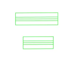
- Windows of Different sizes 3' X 4' & Ventilator of size 26" X 2' are taken.
- Provide the Lintels of 18" X 4".

Now,
- In order to draw the architectural plan we ue various architectural blocks
- For this go to Insert Tab
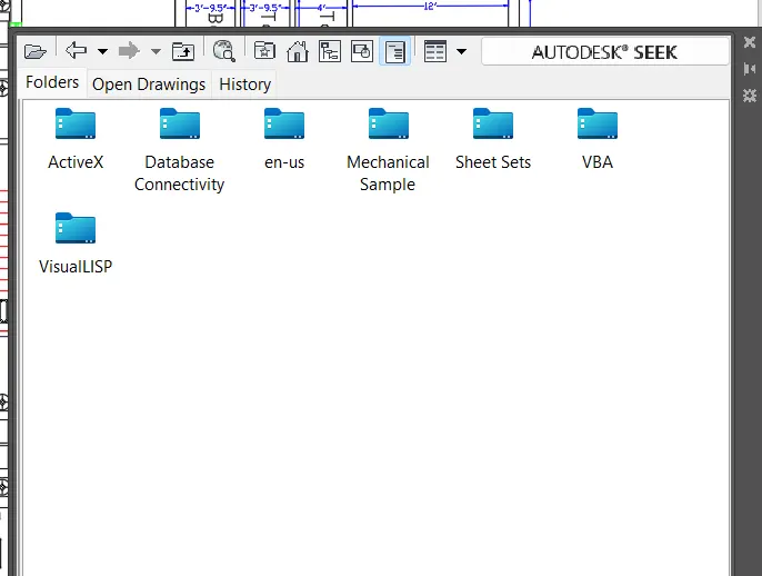
- Then go to Design Centre
- The following Dialogue box appears.
- From there you can select the required blocks.
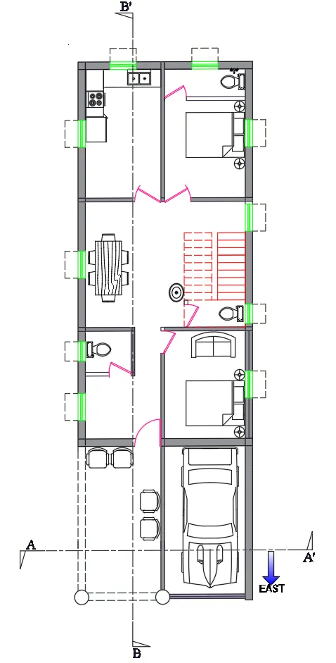
So, we have the following architectural plan,
Now,
- Let us draw the Section AA'
- Take xline to draw the different lines.
- Draw the two circular columns uptil footing .
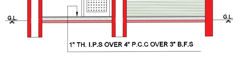
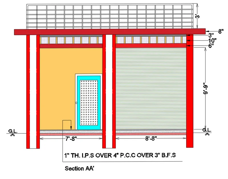
- Give 3" BFS i.e., Brick Flat sole.
- Over BFS give 4" thick PCC i.e., plan concrete cement.
- Over PCC give 1"thick I.P.S Indian patent stone .
Now,
- DRAW the shutteing for the car park.
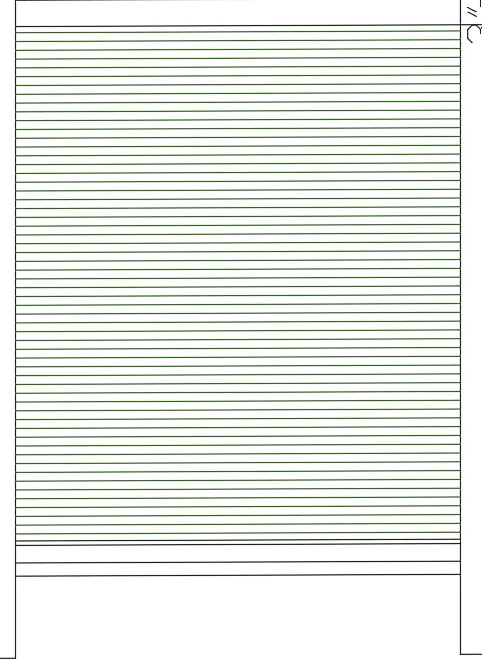
- Draw a line 8'8" and do offset multiple times taking 1" offset distance.
- From the properties panel
- Select the colour 86 and line weight 0.50mm.
Also,
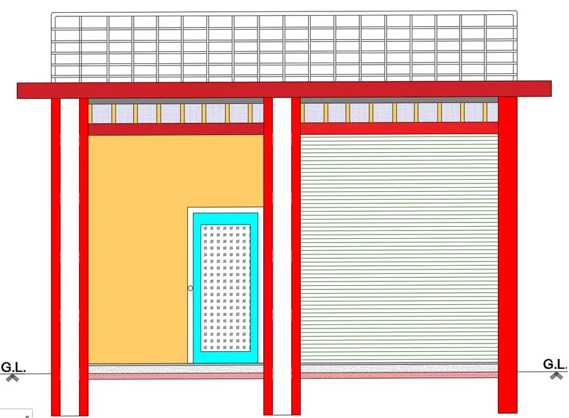
- Some aesthetical objects are drawn and are hatched since it is the entrance of the building.
- A 8" thickness slab is drawn extending to 1' as the lintel.
- Draw one more slab of thickness 3" in between the external columns.
- Draw 10" glass type slab in between the external columns.
- Draw one more slab of thickness 6" in between the external columns.

Also,
- Provide the steel railing parapet wall.
- Height of the steel railing is 3'.

So, final drawing of Section AA' is as below,
Now, its time for dimension,
- Type D or dimension
- A dialogue box appears
- Give texts size as 6".
- Arrow size as 5".
- Click close .
So the drawing of Section AA' is
Now,
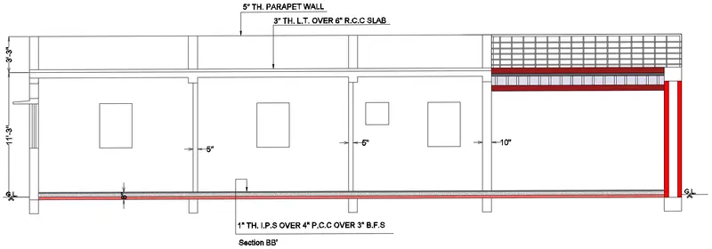
- Let us draw the Section BB'
- Take xline to draw the different lines.
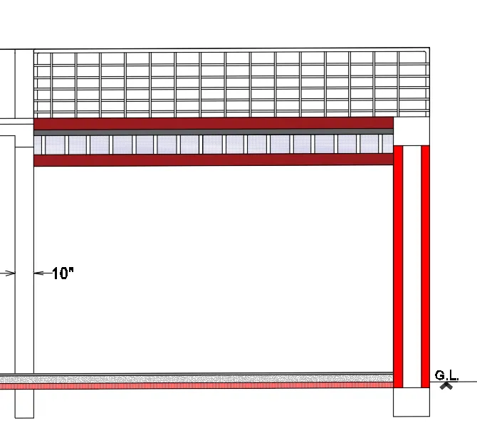
- Draw the two circular columns uptil footing .
- Give 3" BFS i.e., Brick Flat sole.
- Over BFS give 4" thick PCC i.e., plan concrete cement.
- Over PCC give 1"thick I.P.S Indian patent stone .
Also,
- Some aesthetical objects are drawn and are hatched since it is the entrance of the building.
- A 8" thickness slab is drawn extending to 1' as the lintel.
- Draw one more slab of thickness 3" in between the external columns.
- Draw 10" glass type slab in between the external columns.
- Draw one more slab of thickness 6" in between the external columns.
Also,
- Provide the steel railing parapet wall.
- Height of the steel railing is 3'.
Now, its time for dimension,
- Type D or dimension
- A dialogue box appears
- Give texts size as 6".
- Arrow size as 5".
- Click close .
So the drawing of Section BB' is
Now, its time 3D Modelling.
- Click on the Workspace Switching Tab
- Change the workspace from 2D drafting and annotation to 3D Modelling.
- Now we are all set to go.
Now,
- Go to SW isometric
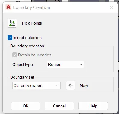
- Make regions by using the boundary command.
- Select Boundary, a popup menu appears
- Select Regions.
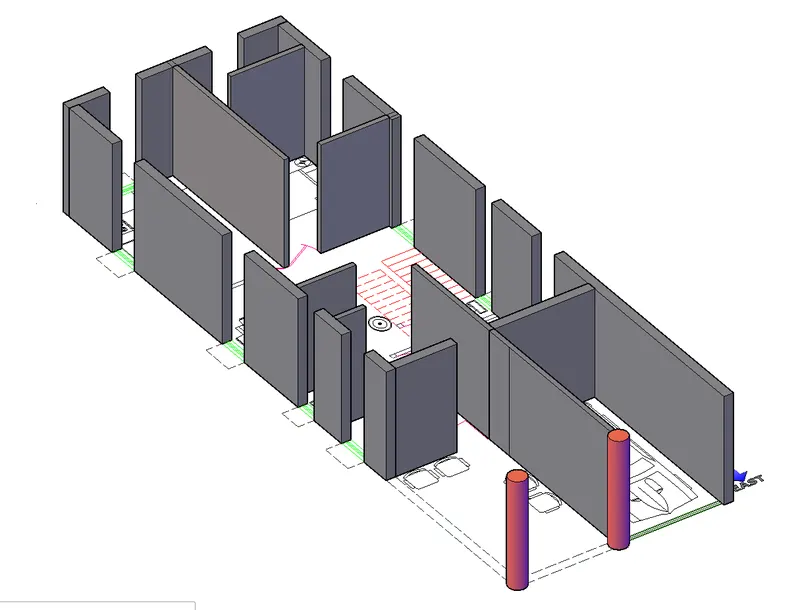
- Extrude the columns.
- And Union it.
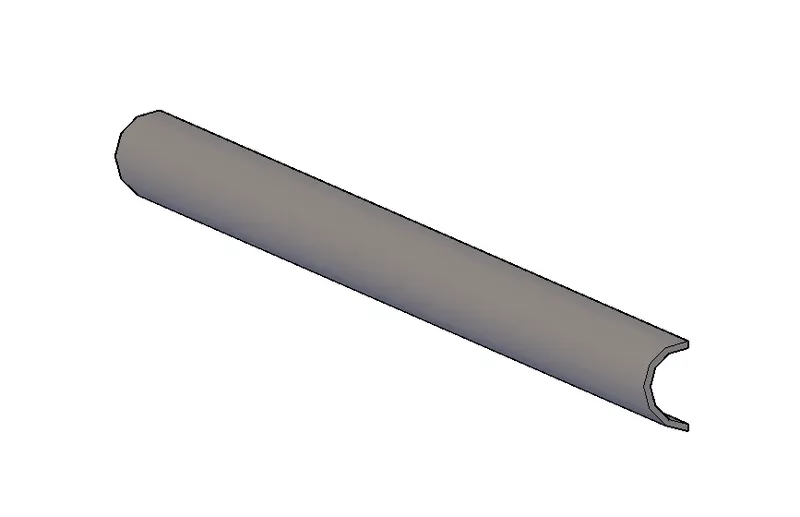
- Now make the shutter
- In order to design the shutter
- First draw a circle of 1.5" radius in 2 wireframe
- Then take offset of 0.25" outer of radius.
- Draw a line cutting the centre
- Trim the one part of circle.
- Make the drawn circle a region then extrude it to 9'.
- Do multiple copies of the above 1 panel uptil height 8'2.7".
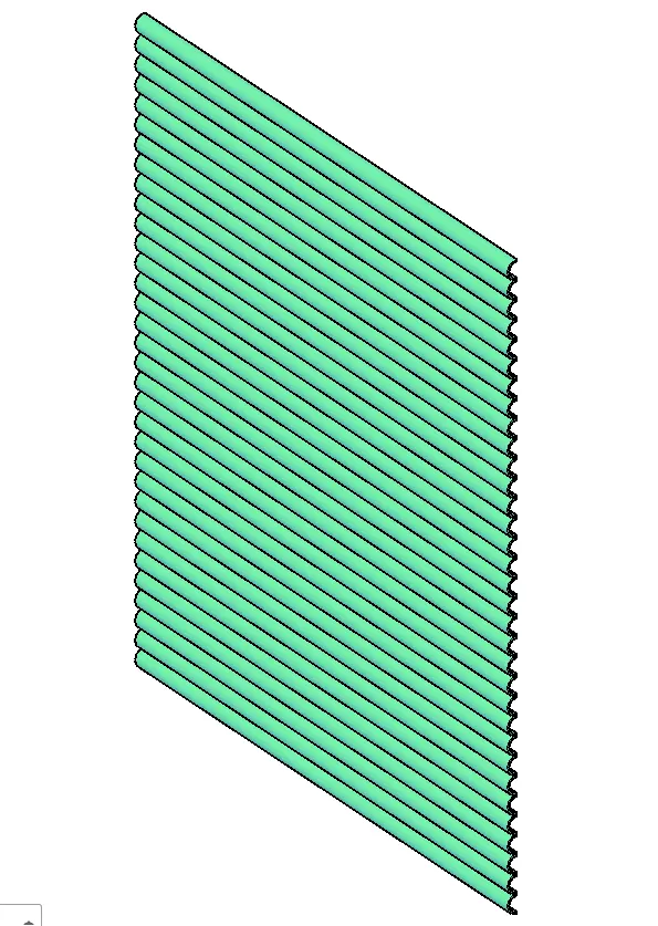
Now,
- Draw the 4" PCC slab at ground level.
- Take 2' extra on both the side.
- Extrude it to 4".
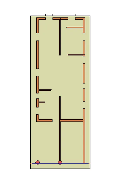
Now,
- Go to top view
- Draw the 8" PCC floor slab
- Extrude it to 8".
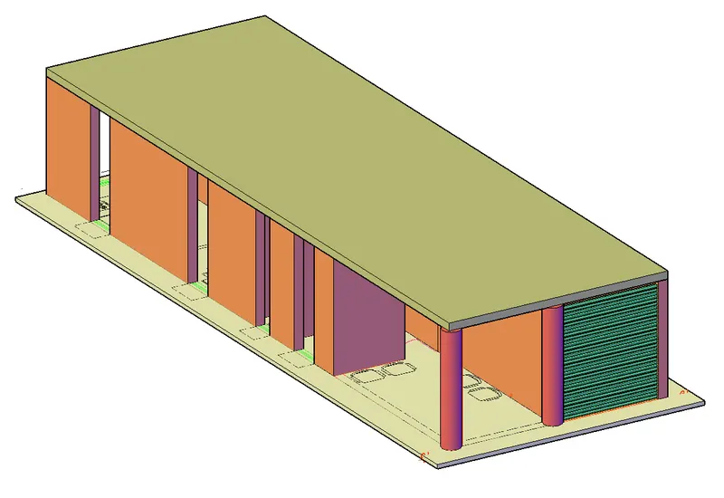
Now,
- Extrude the window 3' from bottom
- And 3' from top
- For this first switch off the floor slab and ground slab.
- Using union command union this.
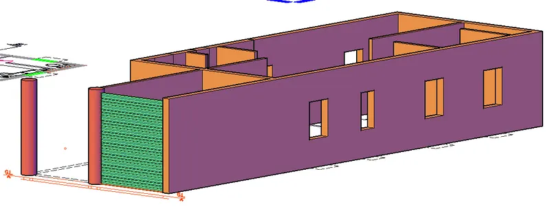
Now,
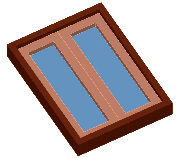
- Draw the window
- Go to 2D wireframe.
- First draw the window in 2D.
- Take different layers of the window as below,
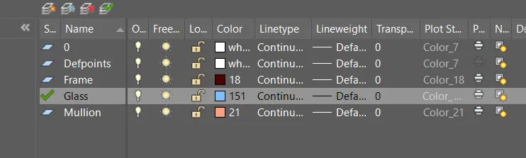
- Extrude it to height of 4'.
Now,
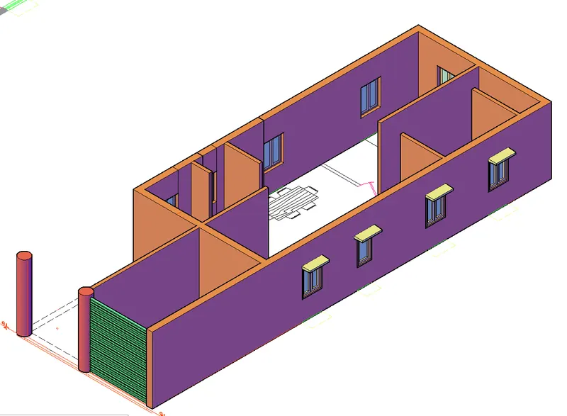
- Draw the window lintel/chajja
- Take thickness 4".
- Do a tapering at 2".
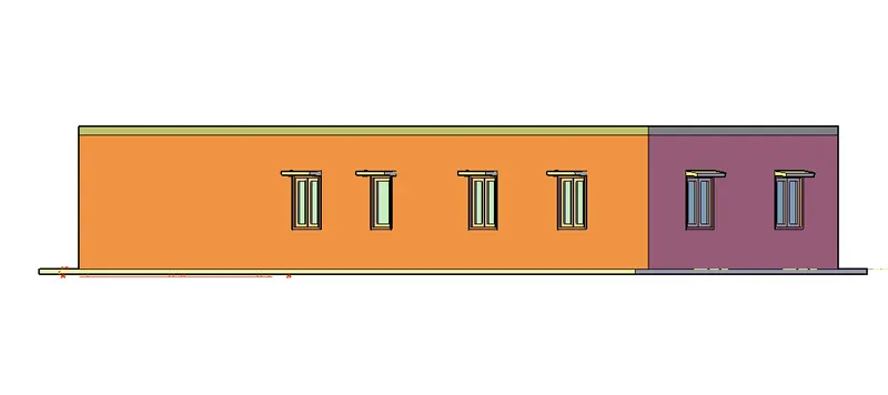
So we have,
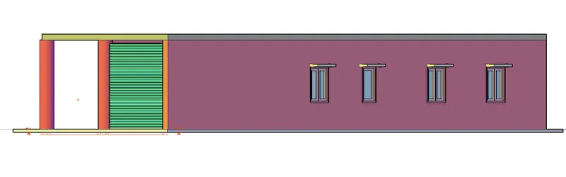
Now,
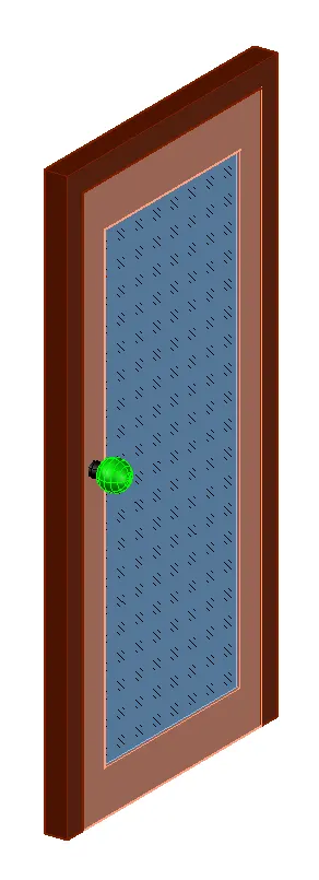
- Draw the door.
- Take the width as 3'.
- Do a length as 7'.
- Take the thickness as 3".
- Also draw the door lock
- For this draw a circle of 1" radius and extrude it to 4".
- Then select sphere from the ribbon and place at its midpoint.
- The door is made of three panel as shown below
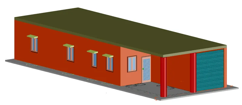
- Put the door in the required as shown below.
Now, union the wall and the roof slab.
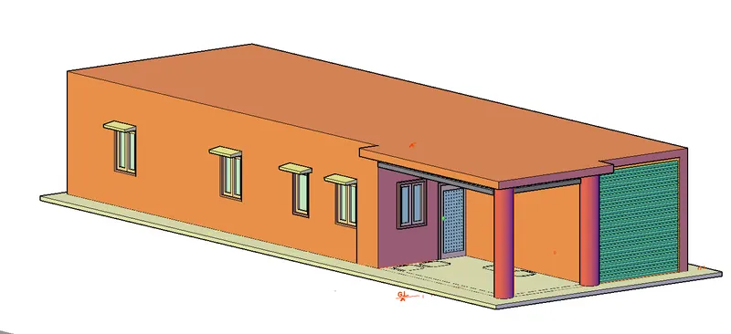
Now, let us give some aesthetic appearance to the entrance as per the elevation.
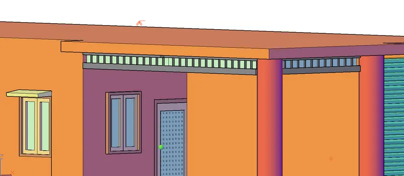
Now,
- Draw the parapet wall.
- Take the height as 3'.
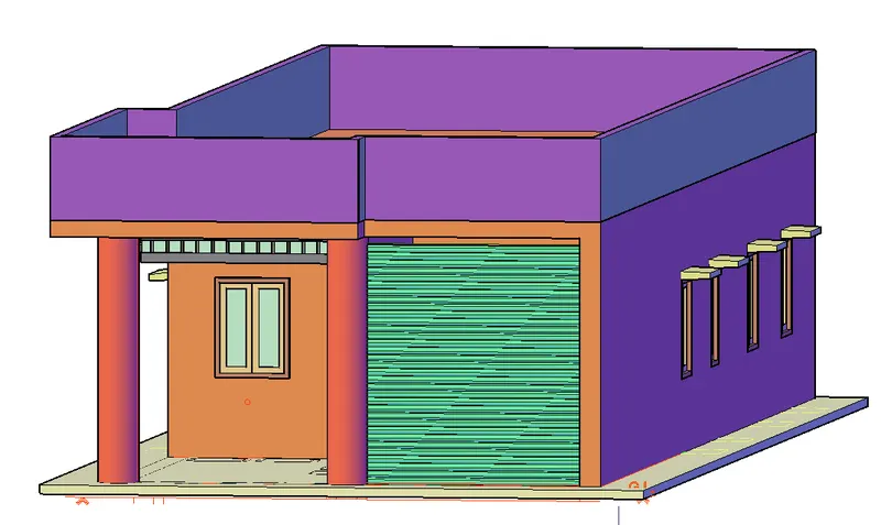
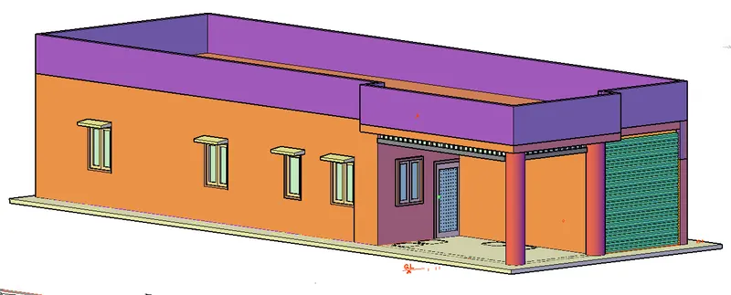
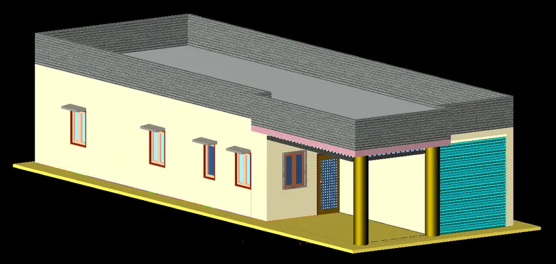
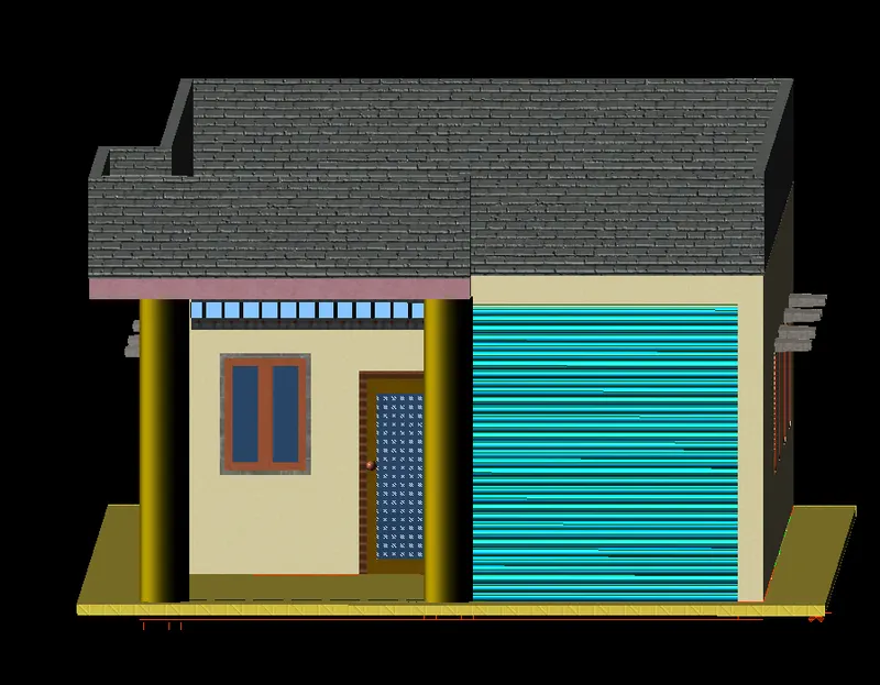
Now, its time for rendering and giving materials to the wall.
- Go to Material Browser
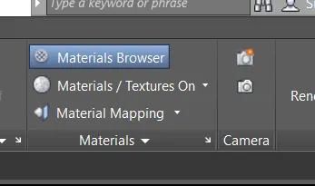
- A popup menu appears
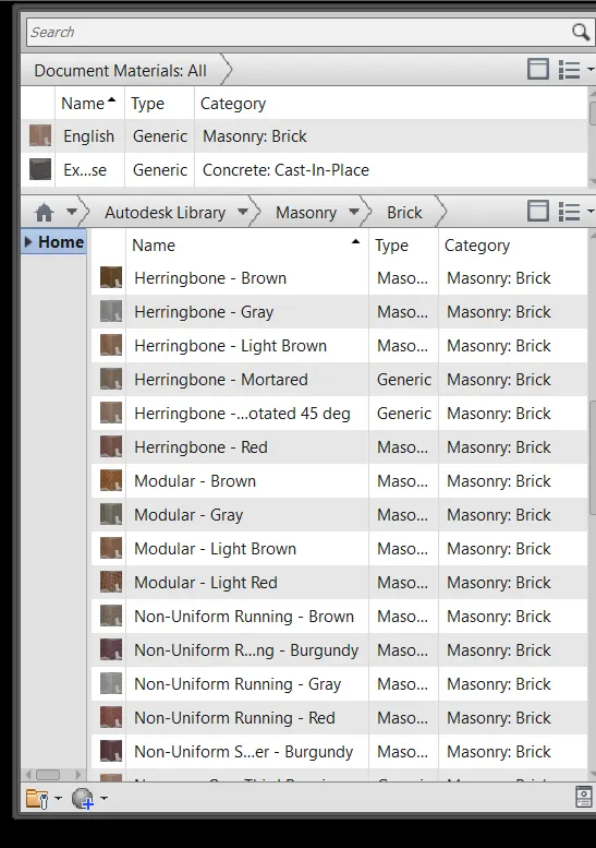
- Give the objects required materials.
- Like give the floor material as Check Black White.
- Give the parapet - Slate Gray
- Similarly give the others materials too.
Now,
- Go to visualise tab.
- Go to render panel.
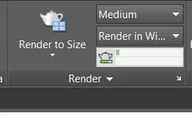
- Type RR for rendering.
RESULT: -