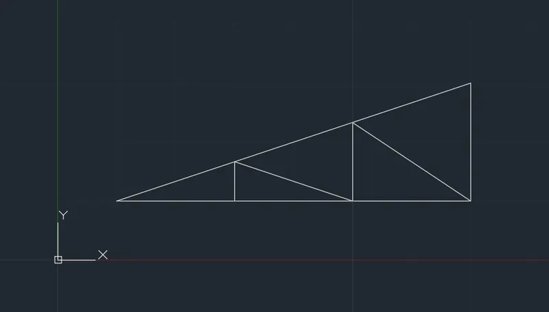
Creation of geometries by Coordinate system methods using AutoCad
A.
AIM: - To create the different geometries as given in the question using coordinates system methods, using AutoCAD.
Introduction: -
There are a total of Four Co-ordinate system which we use in AutoCAD,
- Absolute Co-ordinate system - In this type of Co-ordinate system method, all the points are taken with respect to the origin.
- Relative Co-ordinate system - In this type of Co-ordinate system method, we refer to a point with respect to the last point that we have already defined.
- Relative Polar Co-ordinate system - In this type of Co-ordinate system method, we are given only two things with which we draw any lines, one is Length and the other one is the angle.
- Direct Distance Entry method - In this type of Co-ordinate system method, we enter the command L (Line), specify the first point and then position the cursor and enter the distance.
Procedure: -
Before we start the drawings we need to set up the drawing as Imperial Template and the units into Decimal Units.
Following are the steps in order to set up the drawing as Imperial Template and the units into Decimal Units.
- Go to Application Menu or click CTRL + N (New)
- Click on New from the Application Menu
- A popup menu appears, click on the first tab known as Start from Scratch > Select Imperial(feet and inches)
- Now click on the third tab known as Use a Wizard > Go to Advance setup > A Dialog box appears > Select the unit of measurement as Decimal > Press Next > select Angle as Decimal Degrees > Press Next > Select Angle Measure > Press Next > Select Angle Direction > Press Next > Select Area > Click Finish
- Now we are all set to go.
For P-1 figure, we have the following steps.
I. Steps of Drawing P-1 Geometry using Absolute Co-ordinate system: -
Type 'L' or line in the command box or select Line tool from the draw tool panel.
- Specify the first point which is given as (2, 1) and press Enter
- Specify the next point which is given as (8, 1) and press Enter
- Specify the next point which is given as (8, 2) and press Enter
- Specify the next point which is given as (3, 2) and press Enter
- Specify the next point which is given as (3, 6) and press Enter
- Specify the next point which is given as (8, 6) and press Enter
- Specify the next point which is given as (8, 7) and press Enter
- Specify the next point which is given as (2, 7) and press Enter
- Specify the next point : Press Close to complete the box
II. Steps of Drawing P-1 Geometry using Absolute Co-ordinate system: -
- Specify the first point which is given as (2, 1) and press Enter (First point is always a absolute point)
- Specify next point : @6,0
- Specify next point: @0,1
- Specify next point : @-5,0
- Specify next point : @0,4
- Specify next point : @5,0
- Specify next point : @0,1
- Specify next point: @-6,0
- Specify next point : Press Close to complete the box
III. Steps of Drawing P-1 Geometry using Relative Polar Co-ordinate system: -
- Specify the first point which is given as (2, 1) and press Enter (First point is always a absolute point)
- Specify next point : @6<0
- Specify next point : @1<90
- Specify next point : @5<180
- Specify next point : @4<90
- Specify next point : @5<0
- Specify next point: @1<90
- Specify next point : @6<180
- Specify next point : @6<270
- Specify next point : Press Close to complete the box
IV. Steps of Drawing P-1 Geometry using Direct Distance Entry method: -
- Specify the first point which is given as (2, 1) and press Enter (First point is always a absolute point)
- Specify next point : 6
- Specify next point : 1
- Specify next point: 5
- Specify next point : 4
- Specify next point : 5
- Specify next point : 1
- Specify next point : 6
- Specify next point :Press Close to complete the box
Result: -
The Resultant drawing that we get from the four methods is as below,
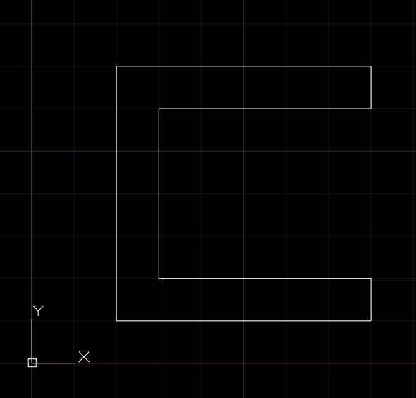
For P-2 figure, we have the following steps.
I. Steps of Drawing P-2 Geometry using Absolute Co-ordinate system: -
Type 'L' or line in the command box or select Line tool from the draw tool panel.
- Specify first point: 2,1
- Specify next point : 5,1
- Specify next point: 5,5
- Specify next point : 6,5
- Specify next point : 6,1
- Specify next point : 9,1
- Specify next point : 7,8
- Specify next point: 4,8
- Specify next point:Press Close to complete the box
II. Steps of Drawing P-2 Geometry using Absolute Co-ordinate system: -
- Specify the first point which is given as (2, 1) and press Enter (First point is always a absolute point)
- Specify next point: @3,0
- Specify next point : @0,4
- Specify next point: @1,0
- Specify next point : @0,-4
- Specify next point : @3,0
- Specify next point : @-2,7
- Specify next point : @-3,0
- Specify next point: Press Close to complete the box
III. Steps of Drawing P-2 Geometry using Relative Polar Co-ordinate system: -
- Specify the first point which is given as (2, 1) and press Enter (First point is always a absolute point)
- Specify next point: @3<0
- Specify next point: @4<90
- Specify next point : @1<0
- Specify next point : @4<270
- Specify next point : @3<0
- Specify next point : @7.28<105.96
- Specify next point : @3<180
- Specify next point : Press Close to complete the box
IV. Steps of Drawing P-2 Geometry using Direct Distance Entry method: -
- Specify the first point which is given as (2, 1) and press Enter (First point is always a absolute point)
- Specify next point : 3
- Specify next point: 4
- Specify next point : 1
- Specify next point : 4
- Specify next point: 3
- Specify next point : 7.28
- Specify next point: 3
- Specify next point : Press Close to complete the box
Result: -
The Resultant drawing that we get from the four methods is as below,
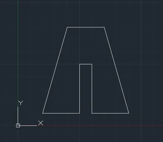
For P-3 figure, we have the following steps.
I. Steps of Drawing P-3 Geometry using Direct Distance Entry method: -
Type 'L' or line in the command box or select Line tool from the draw tool panel.
- Specify first point: 2,1
- Specify next point : 1
- Specify next point : 4
- Specify next point : 2.83
- Specify next point : 4
- Specify next point : 1
- Specify next point : 7
- Specify next point : 1
- Specify next point : 3.60
- Specify next point : 3.60
- Specify next point: 1
- Specify next point :Press Close to complete the box
Result: -
The Resultant drawing that we get is as below,
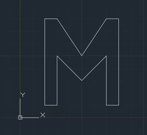
For P-4 figure, we have the following steps.
I. Steps of Drawing P-4 Geometry using Direct Distance Entry method: -
Type 'L' or line in the command box or select Line tool from the draw tool panel.
- Specify first point: 2,1
- Specify next point : 1
- Specify next point : 7
- Specify next point : 5
- Specify next point : 6
- Specify next point : 3
- Specify next point: 1
- Specify next point : 4
- Specify next point : 8
- Specify next point : 7
- Specify next point : Press Close to complete the box
Result: -
The Resultant drawing that we get is as below,
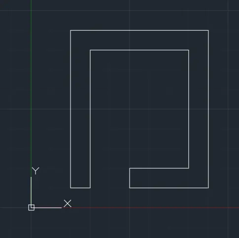
For P-5 figure, we have the following steps.
Step I. Drawing outer box using Direct Distance Entry method: -
Type 'L' or line in the command box or select Line tool from the draw tool panel.
- Specify first point: 2,1
- Specify next point : 8
- Specify next point: 6
- Specify next point : 8
- Specify next point : Press Close to complete the box

Step II. Drawing the two inside boxes using Direct Distance Entry method: -
Type 'L' or line in the command box or select Line tool from the draw tool panel.
- Specify first point: 3,2
- Specify next point : 2
- Specify next point : 3
- Specify next point : 2
- Specify next point : Press Close to complete the box
Again, type 'L' or line in the command box or select Line tool from the draw tool panel.
- Specify first point: 6,2
- Specify next point : 2
- Specify next point : 3
- Specify next point : 2
- Specify next point : Press Close to complete the box
Result: -
The Resultant drawing that we get is as below,
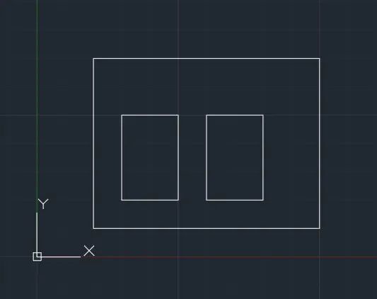
For P-6 figure, we have the following steps.
Step I. Drawing given figure using Direct Distance Entry method: -
Type 'L' or line in the command box or select Line tool from the draw tool panel.
- Specify first point: 0,0
- Specify next point: 10
- Specify next point : 2
- Specify next point : 4
- Specify next point : 4
- Specify next point : 3
- Specify next point : 2
- Specify next point : 8
- Specify next point : 2
- Specify next point : 3
- Specify next point : 4
- Specify next point : 4
- Specify next point :Press Close to complete the box
Result: -
The Resultant drawing that we get is as below,
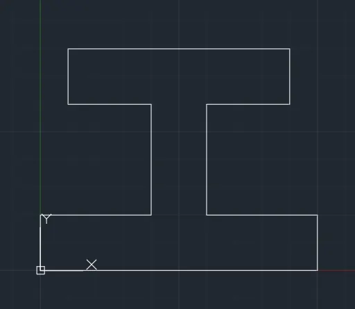
For P-7 figure, we have the following steps.
Step I. Drawing the given figure using Direct Distance Entry method: -
Type 'L' or line in the command box or select Line tool from the draw tool panel.
- Specify first point: 1,1
- Specify next point : 5
- Specify next point : 2
- Specify next point: 3
- Specify next point: 1
- Specify next point : 1
- Specify next point : 2
- Specify next point: 3
- Specify next point : 2
- Specify next point : 4.472
- Specify next point : Press Close to complete the box
Result: -
The Resultant drawing that we get is as below,
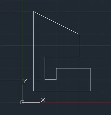
For P-8 figure, we have the following steps.
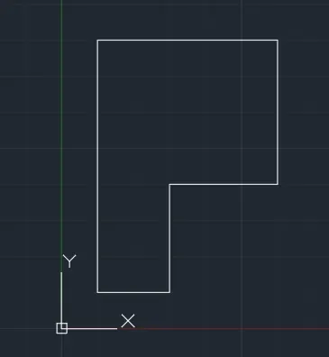
Step I. Drawing outer box using Direct Distance Entry method: -
Type 'L' or line in the command box or select Line tool from the draw tool panel.
- Specify first point: 1,1
- Specify next point : 2
- Specify next point : 3
- Specify next point : 3
- Specify next point: 4
- Specify next point: 5
- Specify next point: Press Close to complete the box
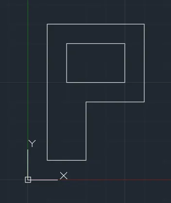
Step II. Drawing the inside box using Direct Distance Entry method: -
Type 'L' or line in the command box or select Line tool from the draw tool panel.
- Specify first point: 2,5
- Specify next point : 3
- Specify next point : 2
- Specify next point : 3
- Specify next point : Press Close to complete the box
Result: -
The Resultant drawing that we get is as below,
-------------------------------------------------------------------------------------------------------------------------------------
B.
AIM: - To draw the profile and the trusses using any coordinate system methods. , using AutoCAD.
Introduction: -
There are a total of Four Co-ordinate system which we use in AutoCAD,
- Absolute Co-ordinate system - In this type of Co-ordinate system method, all the points are taken with respect to the origin.
- Relative Co-ordinate system - In this type of Co-ordinate system method, we refer to a point with respect to the last point that we have already defined.
- Relative Polar Co-ordinate system - In this type of Co-ordinate system method, we are given only two things with which we draw any lines, one is Length and the other one is the angle.
- Direct Distance Entry method - In this type of Co-ordinate system method, we enter the command L (Line), specify the first point and then position the cursor and enter the distance.
Procedure: -
Before we start the drawings we need to set up the drawing as Imperial Template and the units into Decimal Units.
Following are the steps in order to set up the drawing as Imperial Template and the units into Decimal Units.
- Go to Application Menu or click CTRL + N (New)
- Click on New from the Application Menu
- A popup menu appears, click on the first tab known as Start from Scratch > Select Imperial(feet and inches)
- Now click on the third tab known as Use a Wizard > Go to Advance setup > A Dialog box appears > Select the unit of measurement as Decimal > Press Next > select Angle as Decimal Degrees > Press Next > Select Angle Measure > Press Next > Select Angle Direction > Press Next > Select Area > Click Finish
- Now we are all set to go.
For PROFILE WOOD, we have the following steps.
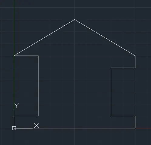
Step I. Drawing outer box using Direct Distance Entry method: -
Type 'L' or line in the command box or select Line tool from the draw tool panel.
- Specify first point: 0,0
- Specify next point : 10
- Specify next point : 1
- Specify next point : 2
- Specify next point: 4
- Specify next point : 2
- Specify next point : 1
- Specify next point: 5.8310
- Specify next point: 5.8310
- Specify next point : 2
- Specify next point : 5
- Specify next point: 2
- Specify next point : Press Close to complete the box
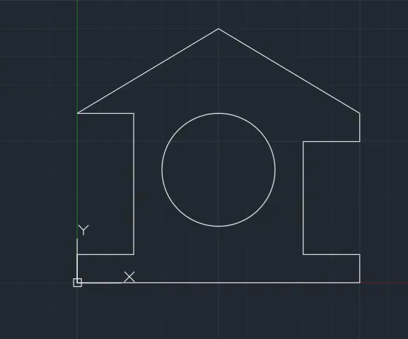
Step II. Drawing the inside circle: -
Type 'C' or Circle in the command box or select Circle tool from the draw tool panel.
- Type 'C' or Circle in the command box
- Specify center point for circle : 5,4
- Specify radius of circle : 2
Result: -
The Resultant drawing that we get is as below,
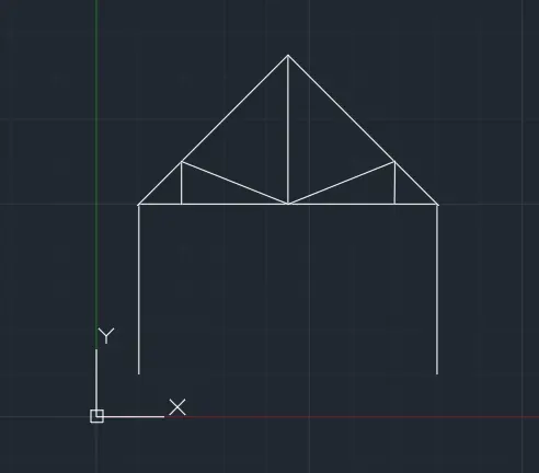
For QUEEN POST TRUSS, we have the following steps.
Step I. Drawing outer box using Direct Distance Entry method: -
Type 'L' or line in the command box or select Line tool from the draw tool panel.
- Specify first point: 1,1
- Specify next point : 4
- Specify next point: 1
- Specify next point : 2.5
- Specify next point : 2.5
- Specify next point: 1
- Specify next point: 4
- Type L or LINE in the command
- Specify next point : 3.5
- Specify next point : 5
- Type L or LINE in the command
- Specify next point : 5
- Type L or LINE in the command
- Specify next point : 1
- Specify next point : 2.7
- Specify next point : 2.7
- Specify next point: 1
Result: -
The Resultant drawing that we get is as below,
For Mono Pitch, we have the following steps.
Step I. Drawing outer box using Direct Distance Entry method: -
Type 'L' or line in the command box or select Line tool from the draw tool panel.
- Type L or LINE in the command
- Specify first point: 1,1
- Specify next point : 2
- Specify next point : 2
- Specify next point : 2
- Specify next point : 2
- Type L or LINE in the command
- Specify first point:
- Specify next point: 0.667
- Specify next point : 1.33*
Result: -
The Resultant drawing that we get is as below,