Creating a Floor plan, Footing detail and Isometric view using AutoCad
AIM: - To create a Floor plan, Footing detail and Isometric view using AutoCad
PROCEDURE: -
Before we start the drawings we need to set up the drawing as Metric Template and the units into Decimal Units.
Following are the steps in order to set up the drawing as Imperial Template and the units into Decimal Units.
- Go to Application Menu or click CTRL + N (New)
- Click on New from the Application Menu
- A popup menu appears, click on the first tab known as Start from Scratch > Select Metric
- Now click on the third tab known as Use a Wizard > Go to Advance setup > A Dialog box appears > Select the unit of measurement as Decimal > Press Next > select Angle as Decimal Degrees > Press Next > Select Angle Measure > Press Next > Select Angle Direction > Press Next > Select Area > Click Finish
- Set the page limit by entering Limits in the command tab. The lower left corner is specified as 0,0 and the upper right corner is specified as 297, 210.
- Now we are all set to go.
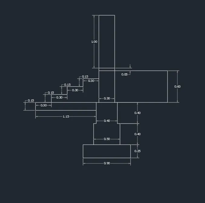
I. Steps of Drawing C.S of Load Bearing Wall Over Spread Footing
Type 'L' or line in the command box or select Line tool from the draw tool panel.
- On the Ortho mode by clicking f8 from the keyboard or by clicking the Ortho mode icon from the menu bar.
- Specify the first point by clicking the cross hair cursor anywhere on the working area
- Positon the cursor to the positive X direction and enter the distance 0.90 m
- Positon the cursor to the positive Y direction and enter the distance 0.25 m
- Positon the cursor to the negative X direction and enter the distance 0.20 m
- Positon the cursor to the negative X direction and enter the distance 0.50 m
- Positon the cursor to the negative X direction and enter the distance 0.20 m
- And then close the box by clicking on the initial point.
Again, type 'L' or line in the command box or select Line tool from the draw tool panel.
- Positon the cursor on 0.20 m from the negative X direction and enter the distance 0.40 in positive Y direction.
- Positon the cursor to the negative X direction and enter the distance 0.05 m
- Positon the cursor to the positive Y direction and enter the distance 0.40 m
- Positon the cursor to the negative X direction and enter the distance 0.05 m
- Positon the cursor to the negative X direction and enter the distance 0.30 m
- Positon the cursor to the negative X direction and enter the distance 0.05 m
- Positon the cursor to the negative Y direction and enter the distance 0.40 m
- Positon the cursor to the negative X direction and enter the distance 0.05 m
- Positon the cursor to the negative Y direction and enter the distance 0.40 m
Again, type 'L' or line in the command box or select Line tool from the draw tool panel.
- Positon the cursor on 0.05 m from the negative X direction and enter the distance 0.60 in positive Y direction.
- Positon the cursor to the negative X direction and enter the distance 0.30 m
- Positon the cursor to the negative Y direction and enter the distance 0.60 m and close the box.
Now,
- Select the Rectangle tool by entering 'RECTANG' command in the command tab.
- Specify the first point as 0.30,1.65 in the command line.
- Select Dimensions option in the command line.
- Specify length of rectangle as 0.30 in the command line. Specify width of rectangle as 0.05 in the command line.
- Move the cursor to the +ve xy quadrant and click ENTER.
Again,
-
Select the Rectangle tool by entering 'RECTANG command in the command tab. Specify the first point as 0.30,1.70 in the command line.
-
Select Dimensions option in the command line.
-
Specify length of rectangle as 0.30 in the command line.
-
Specify width of rectangle as 1.00 in the command line.
-
Move the cursor to the +ve xy quadrant and click ENTER
Again,
- Select the Rectangle tool by entering 'RECTANG' command in the command ta Specify the first point as 0.25,1.05 in the command line.
- Select Dimensions option in the command line.
- Specify length of rectangle as 1.15 in the command line.
- Specify width of rectangle as 0.15 in the command line. Move the cursor towards the left and click ENTER.
Now,
- Select the Line tool by entering 'LINE' command in the command tab.
- Specify the first point as -0.60,1.05 in the command line.
- Specify the coordinate of next point as @0,0.15 in the command line.
- Specify the coordinate of next point as @0.30,0 in the command line.
- Specify the coordinate of next point as @0,0.15 in the command line.
- Specify the coordinate of next point as @0.30,0 in the command line.
- Specify the coordinate of next point as @0,0.15 in the command line.
- Specify the coordinate of next point as @0.30,0 in the command line.
- Press Esc' to cancel the LINE command.
- Select the Trim tool by entering TR command in the command tab.
- Press ENTER.
- Select Edge option; and click on No Extend.
- Click on the line between the second and third rectangle
- Press Esc' to cancel the TRIM command.
- Enter DST command in the command tab to open the Dimension Style Manager.
- Click on the Modify tab.
- Under the Lines option change the colour of the dimension and extension lines.
- Under the Symbols and Arrows option change the Arrow size to 0.05.
- Under the Text option change the Text height to 0.05.
- Click OK. Then click on Set Current and Close the dialog box.
- Select the Dimension tool by entering 'DIM' in the command line.
- Select the first point and second point of the object to be measured, then drag the din location. Repeat for all the objects to be measured.
RESULT: -
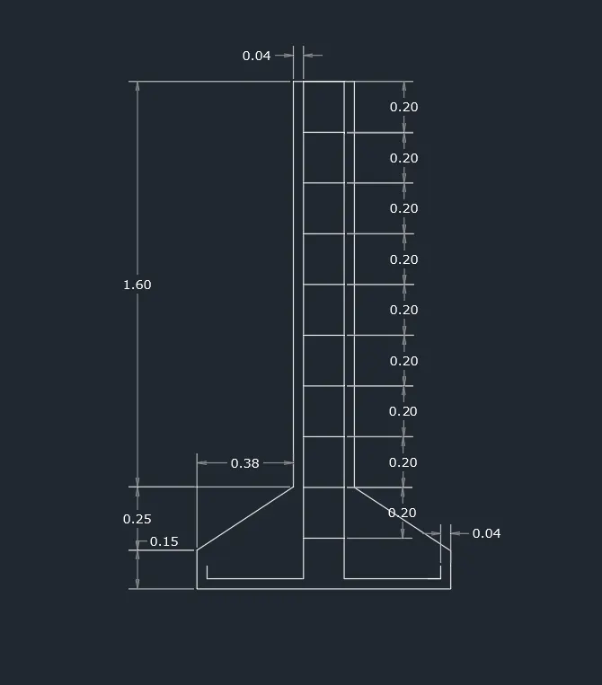
II. Steps of Drawing C.S of Isolated Footing
- Select the Line tool by entering 'LINE' command in the command tab.
- Specify the first point as 0,0 in the command line.
- Specify the coordinate of next point as @1.00,0 in the command line.
- Specify the coordinate of next point as @0,0.15 in the command line.
- Specify the coordinate of next point as @-0.38,0.25 in the command line.
- Specify the coordinate of next point as @0,1.60 in the command line.
- Specify the coordinate of next point as @-0.24.0 in the command line.
- Specify the coordinate of next point as @0,-1.60 in the command line.
- Specify the coordinate of next point as @-0.38,-0.25 in the command line.
- Click 'Close' on the command line.
- Select the Line tool by entering 'LINE' command in the command tab.
- Specify the first point as 0.42,2.00 in the command line.
- Specify the coordinate of next point as @0,-1.96 in the command line.
- Specify the coordinate of next point as @-0.38,0 in the command line.
- Specify the coordinate of next point as @0,0.04 in the command line.
- Press 'Esc' to cancel the LINE command.
- Select the Mirror tool by entering 'MIRROR' command in the command tab.
- Select the objects to mirror (i.e object drawn above) and click ENTER
- Select first point of mirror line.
- Select second point of mirror line.
- Click No in the "Erase source object?" prompt.
- Select the Offset tool by entering 'OFFSET command in the command tab.
- Enter 0.20 as offset distance in the command line.
- Select the top most line of the footing drawing.
- Specify the point on side to offset.
- Repeat the same process for 8 more times.
- Press 'Esc' to cancel the OFFSET command..
- Select the Trim tool by entering 'TR' command in the command tab.
- Press ENTER.
- Select Edge option; and click on No Extend.
- Select the edges of the offset lines having distance of 0.20.
- Press 'Esc' to cancel the TRIM command.
- Enter 'DST command in the command tab to open the Dimension Style Manager dialog box.
- Click on Standard
- Click on the Modify tab.
- Select the arrow size as 0.18 and the text size as 0.18
- Rest leave everything as it is.
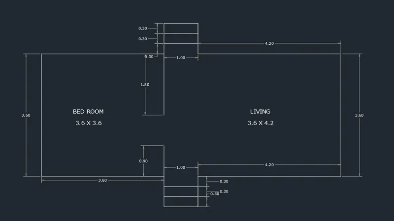
III. Steps of Drawing Line Diagram of a two Bedroom Building
Type 'L' or line in the command box or select Line tool from the draw tool panel.
- On the Ortho mode by clicking f8 from the keyboard or by clicking the Ortho mode icon from the menu bar.
- Specify the first point by clicking the cross hair cursor anywhere on the working area
-
Specify the first point as 0,0 in the command line.
-
Specify the next point as 4.20, pointing the cursor towards the +ve x-direction.
-
Specify the next point as 3.60, pointing the cursor towards the +ve y-direction.
-
Specify the next point as 4.20, pointing the cursor towards the -ve x-direction.
-
Specify the next point as 0.90, pointing the cursor towards the +ve y-direction.
-
Specify the next point as 1.00, pointing the cursor towards the -ve x-direction.
-
Specify the next point as 0.90, pointing the cursor towards the -ve y-direction.
-
Specify the next point as 3.60, pointing the cursor towards the -ve x-direction.
-
Specify the next point as 3.60, pointing the cursor towards the -ve y-direction.
-
Specify the next point as 3.60, pointing the cursor towards the +ve x-direction.
-
Specify the next point as 0.09, pointing the cursor towards the -ve y-direction
-
Specify the next point as 1.00, pointing the cursor towards the +ve x-direction.
-
Click 'Close' on the command line.
- Select the Offset tool by entering 'OFFSET' command in the command tab.
- Enter 0.30 as offset distance in the command line.
- Select the line of length 1.00, for the stairs at the north of the plan.
- Specify the point on side to offset.
- Repeat the same process for both the stairs according to the given drawing.
- Press 'Esc' to cancel the OFFSET command.
- Select the Line tool by entering 'LINE' command in the command tab.
- To draw the partition wall, specify the first point at the corner of the stairs in the north direction.
- Specify the next point as 1.80, pointing the cursor towards the -ve y-direction.
- Press 'Esc' to cancel the LINE command.
- Select the Line tool by entering 'LINE' command in the command tab.
- Specify the first point at the corner of the stairs at the bottom of the diagram.
- Specify the next point as 0.90, pointing the cursor towards the +ve y-direction.
- Press 'Esc' to cancel the LINE command.
- Enter 'DST command in the command tab to open the Dimension Style Manager dialog box.
- Click on Standard
- Click on the Modify tab.
- Select the arrow size as 0.18 and the text size as 0.18
-
Enter TEXT command in the command line.
-
Specify the start point of text as required.
-
Specify height of text as 0.12.
-
Specify angle of rotation of text as 0.00.
-
Enter the name of the drawing.
-
Copy the text box to the different locations and type in the name and size of the rooms.
-
Click Enter and press Esc.
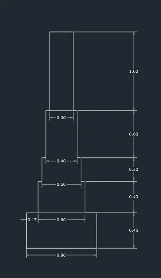
IV. Steps of Drawing C.S of Load Bearing Wall
- Select the Rectangle tool by entering 'RECTANG' command in the command tab.
- Specify the first point as 0,0 in the command line.
- Select Dimensions option in the command line.
- Specify length of rectangle as 0.90 in the command line.
- Specify width of rectangle as 0.45 in the command line.
- Move the cursor to the +ve xy quadrant and click ENTER.
- Select the Line tool by entering 'LINE' command in the command tab.
- Keep the Ortho mode ON.
- Specify the first point as 0.15,0.45 in the command line.
- Specify the next point as 0.40, pointing the cursor towards the +ve y-direction.
- Specify the next point as 0.05, pointing the cursor towards the +ve x-direction.
- Specify the next point as 0.30, pointing the cursor towards the +ve y-direction.
- Specify the next point as 0.05, pointing the cursor towards the +ve x-direction.
- Specify the next point as 0.40, pointing the cursor towards the +ve x-direction.
- Specify the next point as 0.60, pointing the cursor towards the -ve y-direction.
- Specify the next point as 0.05, pointing the cursor towards the +ve x-direction.
- Specify the next point as 0.30, pointing the cursor towards the -ve y-direction.
- Specify the next point as 0.05, pointing the cursor towards the +ve x-direction.
- Specify the next point as 0.40, pointing the cursor towards the -ve y-direction.
- Press 'Esc' to cancel the LINE command.
- Select the Line tool by entering 'LINE' command in the command tab.
- Specify the first point as 0.30,1.75 in the command line.
- Specify the coordinate of next point as @0,1.00 in the command line.
- Specify the coordinate of next point as @0.30,0 in the command line.
- Specify the coordinate of next point as @0,-1.00 in the command line.
- Press 'Esc' to cancel the LINE command.
- Enter 'DST command in the command tab to open the Dimension Style Manager dialog box.
- Click on Standard
- Click on the Modify tab.
- Select the arrow size as 0.18 and the text size as 0.18
- Rest leave everything as it is.
RESULT: -
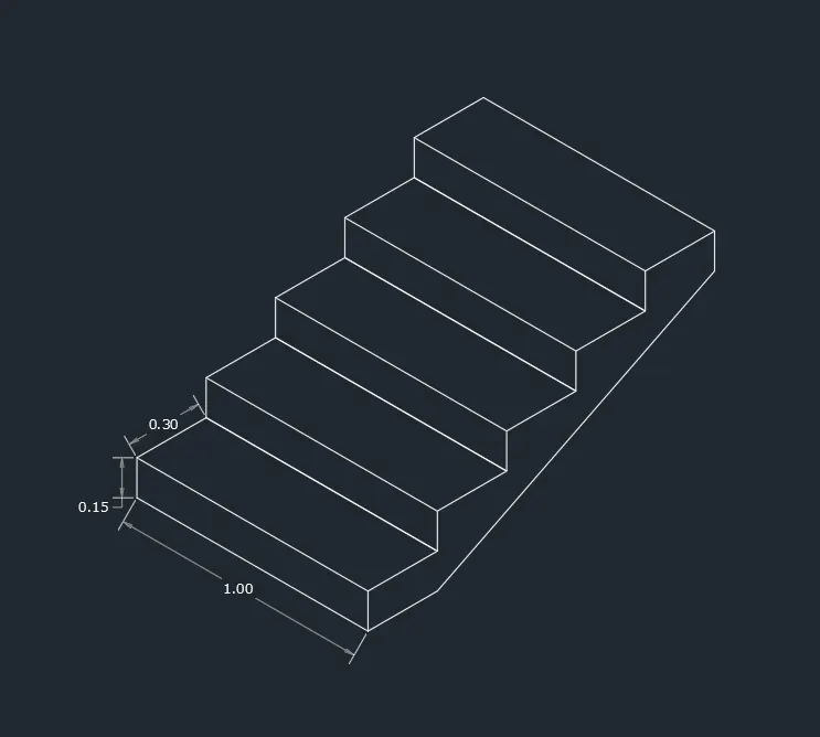
V. Steps of Drawing Isometric View of Steps
For Isometric view we need to Turn on the Isometric Drafting from the menu bar or invoke f5 or Function + f6 for different Isometric views
Now,
- Select Isoplane Left.
- Select the Line tool by entering 'LINE' command in the command tab.
- Keep the Ortho mode ON.
- Specify the first point as 0,0 in the command line.
- Specify the next point as 1.00, pointing the cursor towards the right direction.
- Specify the next point as 0.15, pointing the cursor towards the upward direction.
- Specify the next point as 1.00, pointing the cursor towards the left direction.
- Specify the next point as 0.15, pointing the cursor towards the downward direction.
- Click 'Close' on the command line.
- Select Isoplane Right from Isometric drafting dropdown list.
- Select the Line tool by entering 'LINE' command in the command tab.
- Keep the Ortho mode ON.
- Specify the first point as top corner of the above object.
- Specify the next point as 0.30, pointing the cursor towards the right direction
- Press 'Esc' to cancel the LINE command.
- Select the Copy tool by entering 'CO' command in the command tab.
- Select the line of length 0.30.
- Specify the basepoint as the left top corner of the previous drawing.
- Copy the line at a distance of 1.00 from the basepoint.
- Press 'Esc' to cancel the COPY command.
- Again select the Copy tool.
- Select the line of 0.30 length copied previously.
- Specify the basepoint at the right top corner of the diagram in the former step.
- Copy it at a distance of 0.15 downward from the basepoint.
- Press 'Esc' to cancel the COPY command.
- Select the Copy tool by entering 'CO' command in the command tab.
- Select the entire figure creted in the above two steps, except the line of length 0.30 at the bottom right portion of the stair step.
- Specify the basepoint as the bottom left corner of the step.
- Copy the entity to the top left corner of the step.
- Repeat the same for three more times to get the desired number of steps.
- Press 'Esc' to cancel the COPY command.
- Select the Copy tool by entering 'CO' command in the command tab. . Select the line of length 1.00 of the topmost step in the previous diagram.
- Specify the basepoint as the corner of the topmost step.
- Copy the line to the top top corner of the last topmost step. Press 'Esc' to cancel the COPY command.
- Select the Line tool by entering 'LINE' command in the command tab.
- Specify the first point as top left corner of the topmost step.
- Specify the next point as 0.15, pointing the cursor towards the downward direction.
- Join the two open edges of the stair.
- Press 'Esc' to cancel the LINE command.
- Enter 'DST command in the command tab to open the Dimension Style Manager dialog box.
- Click on Standard
- Click on the Modify tab.
- Select the arrow size as 0.18 and the text size as 0.18
- Rest leave everything as it is.
- Type DIMALI or select Aligned dimension from the Annotation panel so that the Isometric drawing dimensions can be measured.
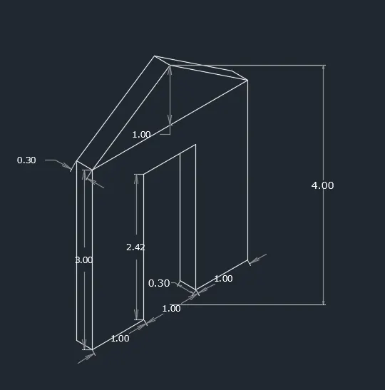
VI. Steps of Drawing Isometric View of Gable Wall
For Isometric view we need to Turn on the Isometric Drafting from the menu bar or invoke f5 or Function + f6 for different Isometric views
- Select Isoplane Left.
- Select the Line tool by entering 'LINE' command in the command tab.
- Keep the Ortho mode ON.
- Specify the first point as 0,0 in the command line.
- Specify the next point as 3.00, pointing the cursor towards the upward direction.
- Specify the next point as 0.30, pointing the cursor towards the left direction.
- Specify the next point as 3.00, pointing the cursor towards the downward direction.
- Click 'Close' on the command line.
- Select Isoplane Right from Isometric drafting dropdown list.
- Select the Line tool by entering 'LINE' command in the command tab.
- Keep the Ortho mode ON.
- Specify the first point as top right corner of the above object.
- Specify the next point as 3.00, pointing the cursor towards the right direction.
- Specify the next point as 3.00, pointing the cursor towards the downward direction.
- Specify the next point as 1.00, pointing the cursor towards the left direction.
- Specify the next point as 2.42, pointing the cursor towards the upward direction.
- Specify the next point as 1.00, pointing the cursor towards the left direction.
- Specify the next point as 2.42, pointing the cursor towards the downward direction.
- Specify the next point as 1.00 pointing the cursor towards the left direction
- Press 'Esc' to cancel the LINE command.
- Select Isoplane left from Isometric drafting dropdown list.
- Keep the Ortho mode ON.
- Select the Line tool by entering 'LINE' command in the command tab.
- Specify the first point at the corner of the door opening.
- Specify the next point as 0.30, pointing the cursor towards the left direction.
- Specify the next point as 2.12, pointing the cursor towards the upward direction.
- Press 'Esc' to cancel the LINE command.
- Select Isoplane right from Isometric drafting dropdown list.
- Keep the Ortho mode ON.
- Select the Line tool by entering 'LINE' command in the command tab.
- Specify the first point at the midpoint of the top line.
- Specify the next point as 1.00, pointing the cursor towards the upward direction.
- Draw line to join the top to the top left corner of the wall
- Press 'Esc' to cancel the LINE command.
- Select the Line tool again by entering 'LINE' command in the command tab, and join the top to the of the wall.
- Press 'Esc' to cancel the LINE command.
- Delete the extra lines.
- Select the Copy tool by entering 'CO' command in the command tab.
- Select the both the lines of the mount.
- Specify the basepoint as the top left corner of the wall.
- Copy the lines of the mount to the adjacent top left corner of the wall.
- Press 'Esc' to cancel the COPY command.
- Select the Line tool by entering 'LINE' command in the command tab.
- Join the midpoint of the front face of the mount to the midpoint of the back face of the mount.
- Press 'Esc' to cancel the LINE command.
- Select the Line tool again by entering 'LINE' command in the command tab.
- Join the remaining top right corners of the wall.
- Press 'Esc' to cancel the LINE command.
- Enter 'DST command in the command tab to open the Dimension Style Manager dialog box.
- Click on Standard
- Click on the Modify tab.
- Select the arrow size as 0.7 and the text size as 0.8
- Rest leave everything as it is.
- Type DIMALI or select Aligned dimension from the Annotation panel so that the Isometric drawing dimensions can be measured.