Project 2_Creating a 3D rendered model for a Residential Building in AutoCad
AIM: Create a 3dimensional model of the residential building with a rendered view.
INTRODUCTION:
1. Firstly, define the units with precision requirement of that drawing. (Here, we have chosen "ARCHITECTURAL" unit type with a precision of 0' 0.00")
2. Draw the sketch in X-Y plane and then extrude it, preceded by 3DROTATE about any given axis command if required.
3. Define the UCSICON option in the VIEW tab for aligning & moving the origin at a specified location.
4. Here, some of the characteristics of the residential building that i have defined as follows:
(a). Plot are of dimensions 20'*60' with EAST facing main gate.
(b). Outer walls are of 9" dimension while inner ones have 4.5".
(c). Sill Level of kitchen window is 4" above the top most step coming in its facing while standing on the staircase.
(d). Stairs have height of risers as 7" and thread of 1'.
(e). There are three lending in the staircase with first one has 3'6"*3', second one has 3.5' * 3.5' and last one is same as second one.
5. Door Frames are fixed at a height of 7' from the floor level while ceiling height is at 10' from the floor level.
6. "Outer walls" and "walls above lintel portion" are not drawn for the clarity purpose though concept will be same as it is already done with inner walls.
7. JAILA/Open ceiling is provided at the back side of the plot in between store & bathroom with dimensions of 4' * 4'.
this portion is hatched with a pattern having a spacing of 1" coloured with yellow colour.
8. Set the “ANNOTATE” Properties by adjusting various options like Lines, Symbols and Arrows, Text, Primary units etc.
For Understanding the characteristics, I have drawn the plan view of the plot.
PROCEDURE:
1. Firstly, Draw the plan view of the plot using "DRAW" toolbar and label it in such a way that visibility will not be obstructed/opaque.
2. After Drawing the plan, be sure to have closed figure so that region/boundary can be created.
3. In case of any opening, we may close the open figure either through fillet option or join option.
4. Sections are converted into regions, followed by EXT extrusion option at any specified height
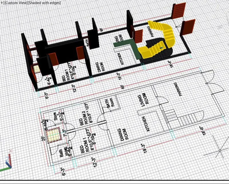
5. Stair steps are drawn in the plan view and then after ensuring about the closed figure, each step is converted into region and move successively into Z-plane with requisite dimensions already explained above in intro-duction.
6. After moving the steps/regions to their location, extrude all the stairs with 2" towards -Z direction, fol-lowed by colouring in dark yellow as depicted in above attached snapshot.
7. Draw the Block with flip option in both perpendicular directions containing the door of 3.5' outer to outer.
8. Insert the Block at the required position in the plan view by modifying through various options like SCALE, ROTATE etc.
9. After placing the Door frame at the required location, explode the block and select the door frame cross-section and convert it into region and then extrude it along the path traced by the defining line.
10. Another Extrusion will be done of doors up to 7' height. (Allott the colour to different regions simultane-ously for eliminating any hodgepodge)
11. Here I have used colour 18 in door frame and colour 22 in door.
12. Judiciously, use different commands like 3DO, 3DROTATE, MOVE, PAN, ZOOM WINDOW etc. for roaming around the 3d model in space frame.
here, Have some snapshots taken while sketching:
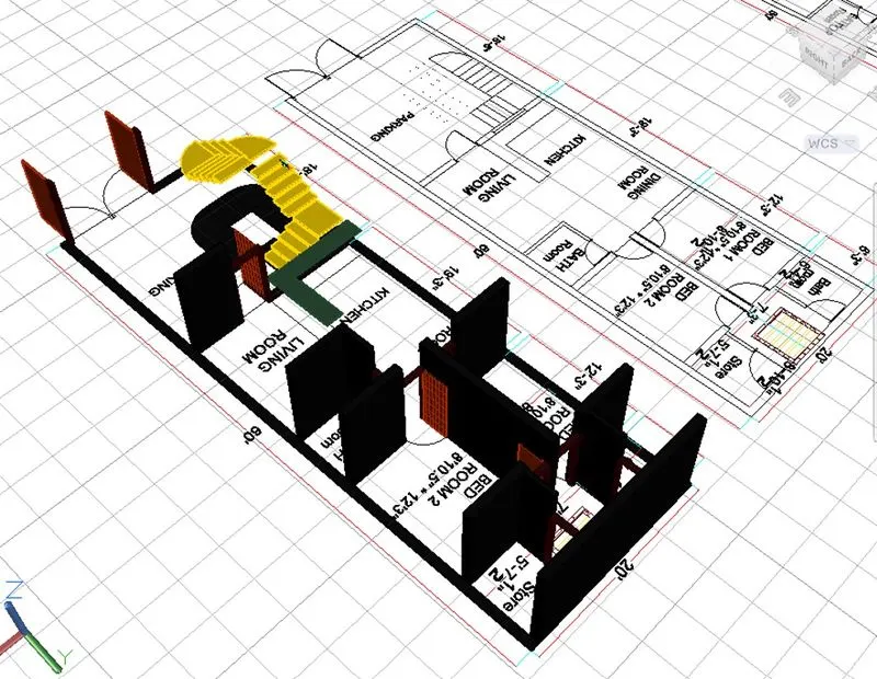
MAIN gate is at east face so decide all the direction accordingly.
NOTE: Black background under the staircase is the plan view of this staircase.
13. Open ceiling/JAILA is shown here by double hatching with red colour having boundary and yellow colour depicting steel bars at a spacing of 1".
14. Walls above lintel portion and Outer walls are not extruded only because of clear visibility, though concept will be same as applied in inner walls to a height of 10'.
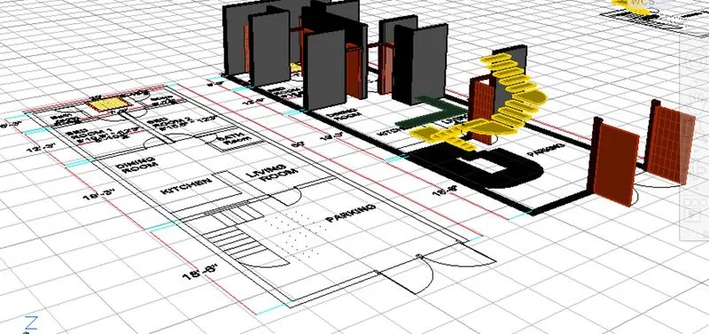
15. Blurred lines in staircase plan view showing the forehead of stairs at a height of 7'.
16. Kitchen slabs is at a height of 3'2" from the floor upto the top face enclosing thickness of 2" within this dimension.
17. Main GATE is of 7.5' with door frame of 8', having an open span of 10'.
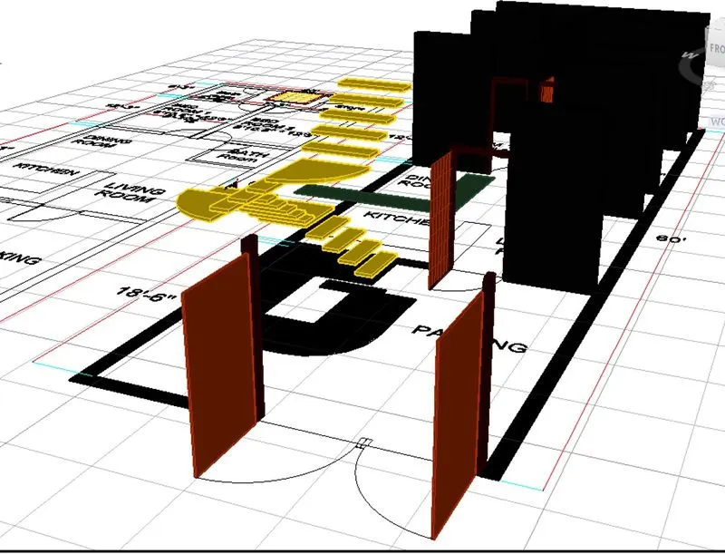
18. Parking area at the front side of this plot is of 20' * 20' and plan dimensions under the stairs are of 10' * 13', taking length of stairs (10') parallel to 20' dimension of plot.
19. All the outer walls and main load bearing walls are of 9" dimension.
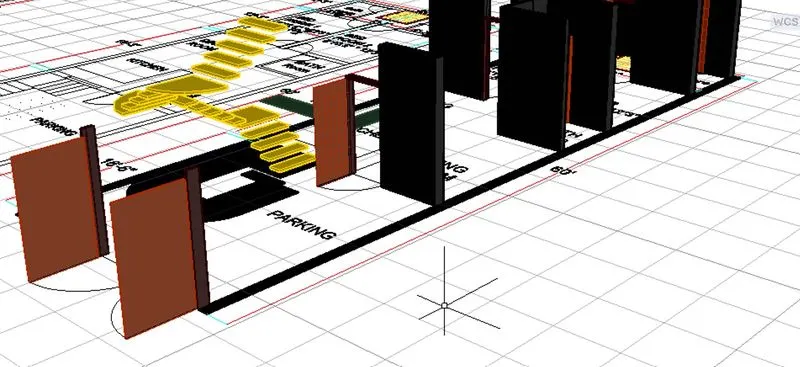
HERE, snipping is done for making the clarity in the sketch otherwise PDF form will get distorted because of use of material browser.
19. Here DINING ROOM & LIVING ROOM are the part of 20' * 20' lobby area along with kitchen & bathroom at the middle of this plot (so, don't mess up the meaning with the name given as Room).
.
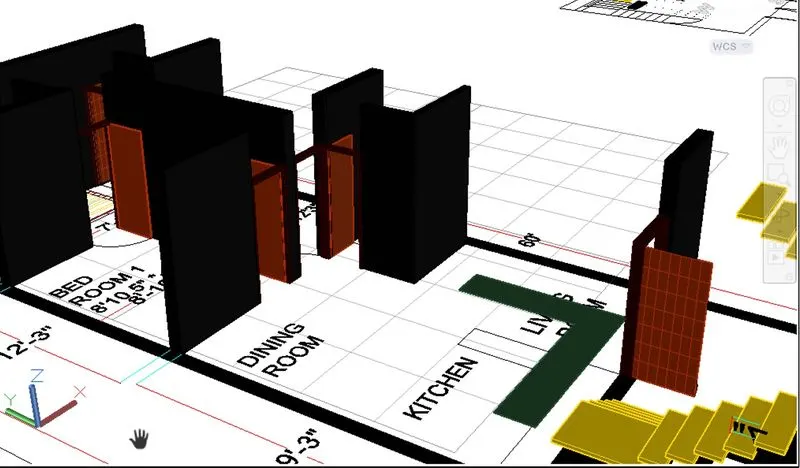
20. Here the gap between the kitchen slab and stairs moving upward is to be filled with a 9" wall having a widow in the centre of kitchen of width 5'.
here, again this part is omitted for making the cleanliness into the above sketch though the concept was same as applied to door frames.
21. Dining room is covered within a configuration of 10' * 10' while Living Room is within 8.5' * 14' adjacent to kitchen.
22. Bathroom depicted in this picture are of 6'3" * 6' with door facing towards south face.
23. Both BEDROOMS have doors in the east face of 3' dimension.
RESULT:
I have attached all the views through snipping tools (in JPG. Form) along with few rendering (in PNG. Form) attached in the browser window below.