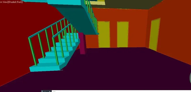
Project 2_Creating a 3D rendered model for a Residential Building in AutoCad
AIM: Create a 3 dimensional model of the residential building with a rendered view.
software that i used AUTOCAD.
Tools i used:
line
layers
offest
trim
multileader.
copy
move
extrude
sweep
subtract
solid edit
region
slice
presspul
union
mirror
step by step procedure:
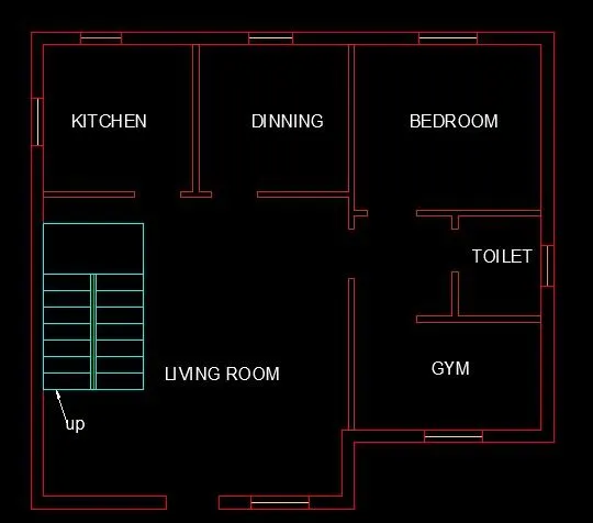
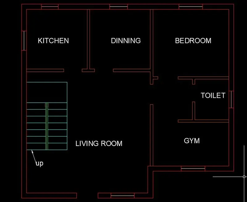
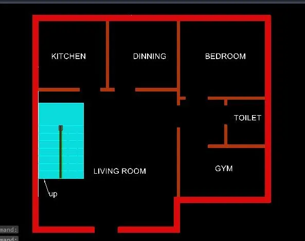
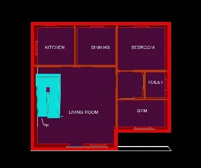
Take rectangle command draw the rectangle with dimension 30'x 30'.
For providing wall thickness take offset command draw the offset line with distance of 9".
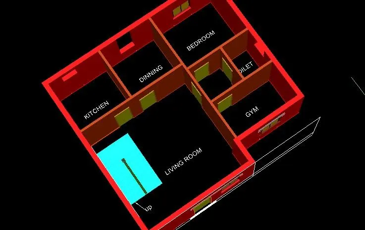
For dividing rooms i used line, offset,trim,fillet and expand .
go to layer properties created the new layers like
assigning the colors, linetype,lineweight to the structural and architectural elements.
i assigned the
exterior wall -1o
interior wall -22
staircase block-130
windows-outer frame, inner frame,panel.
door-frame and panel.
lintel-8
railing-80
ventilator-210.
floor-21
plinth-216
assigned the each layer to the element.
make the exterior wall seperate assigned the 30 ,continuous line light weight as per the layer.
make them unite.
make the interior wall seperate assigned the 22,continous line weight as per the layer.
make the exterior in to region by using boundary clicking of pick points.
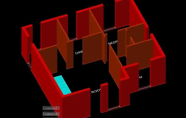
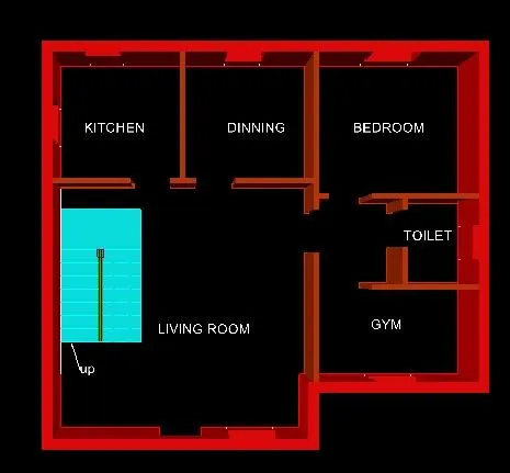
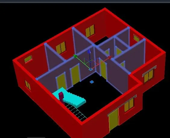
extrude to 10' some walls are 3' because there is openings for window and some are for doors 3' from the top.
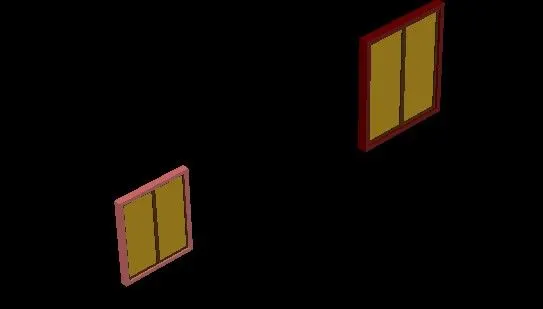
preparing the windows and doors
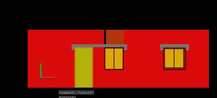
draw the rectangle with dimension of 3' x 6'10".
offset to 3" for outer frame and 2" for inner frame and remainging for panel.
while making the windows and doors we have to switch the layers consecvately.
first you have to make outer frame in to region.and take subtract the partial region from the main region .
assign it according to the degrade.
start from the whole not start from small to parts.
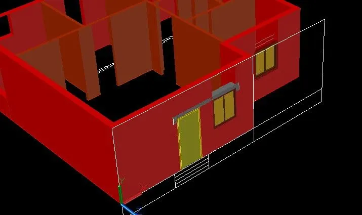
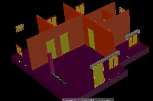
place the doors and windows in the opening space.
next switch to pink for making verandhah.
place it the with the height of 2'.
move the window and door some what inside the wall.
i change the dimmension by go to scale reference.
provide the lintels over the door and window.
you neeed to create the lintel replica model and to be subrated fro the main region.(wall).
use the object snap place it at the correctt defined position.
extruded it to 3' from the slab.
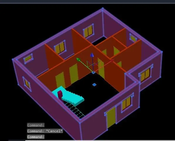
put the external wall in layoff.
create the plinth with distance of 6".
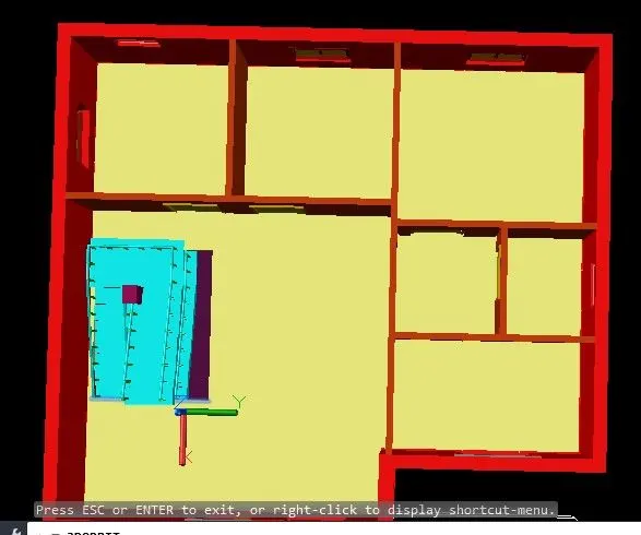
put the plan of staircase outside from the plan.
put the visual style in 2d wireframe and make the side view shift the 2d wireframe and make it in to region.
rotate in y-axis with 90 degree.
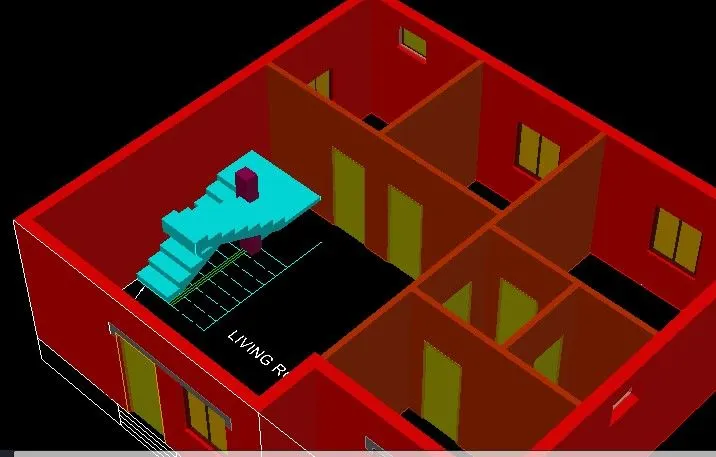
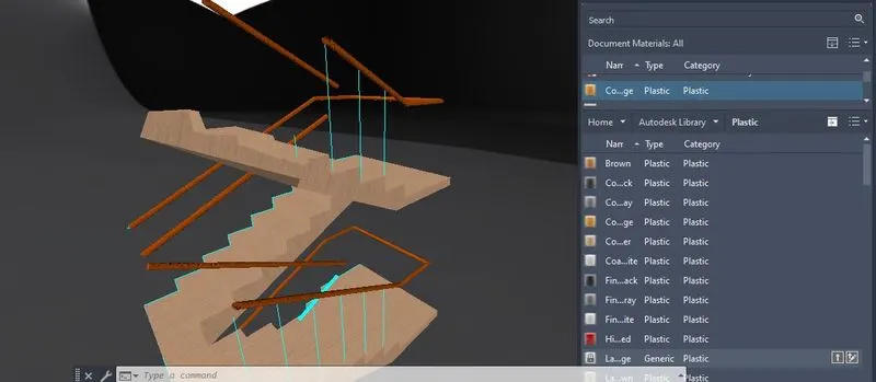
extrude the staircase provide the each step with 1' distance for the thread.
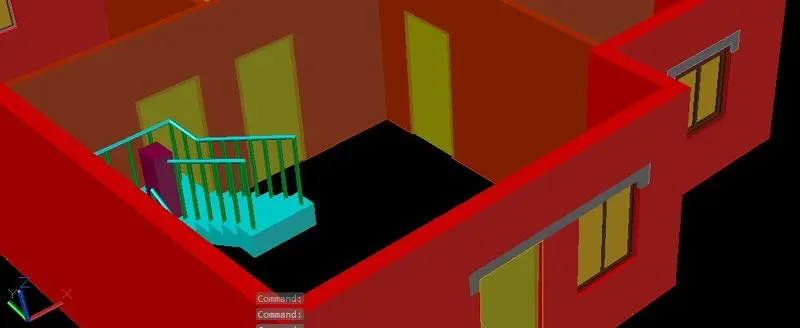
providing the railing with the help of circle and and cylindrical .
with the help of sweep we also make bassuleant(handler)with unfiorm cross section.
for supporting the stairblock i provided a column with dimension 1'x1'.
extrude it up to where the second flight start and resume it.
take mirror command (or) extract edges to make another flight.
with again from non region to the extrude.
make the exterior wall unite with the help of union.
make the interior wall unite with the help of union.
take copy of the profile make it into group put it side .
take plinth layer put ucs in the top draw the line by taking polyline command,
make it in to region and extrude -6" (z-axis).
take foor provide the slab inside the wall.
subtract some portion for accesible to the staircase passengers.one to another floor.
provide rail for supporting purpose.
copy the first floor take the reference as the second step.
provide the balcony take solidedit go to face extrude(or)offset you can make the 4.5"x 3'.
provide the head room to protect or entrance for terrace .
It is covered the pitched roof clay sheets we can make it by through tabulated surface.
I provided the balcony for the first floor with dimension of 4'x 3' and made it in to region .
Take extrude tools provide the path it extrude the provided path and create the wall around it.
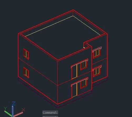
after creating the 3d model
visuliation
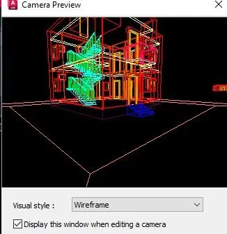
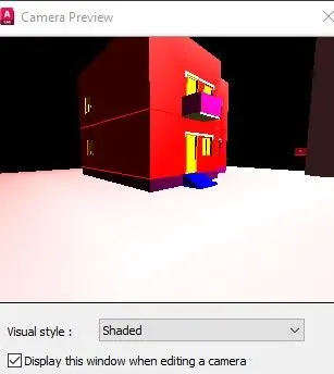
take a camera placed at the height of 6'.
at some distant from the buiding i took 20 mm because i want wide angle.
save the some view by the view command.
we can see the view in the different visual style.
i took the distant light set it from 2 times of the building.
set the exposure condition as per the convience.
type the mat command in the command box. one dialog box will open then select the different generic material assign to your elements
while i assigning it shows you dont have access to use it.
after assigning the materials you can go for the material mapping by the command called set uv.
take box tool fix the size up to our convience.
go to the render panel set the render in window format.
you can see the render view after assigning material.
open the one by one view see the light affect and exposure condition.
after i trailed all types i select dropdown in the render panel.
one dialog box will open select one format you want the save the render.
i put the high quality.
i save the render view of the residential 3d model.
Result:
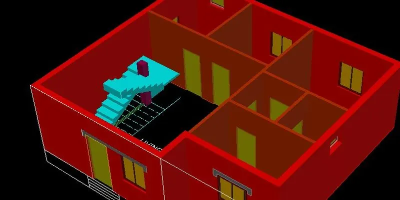
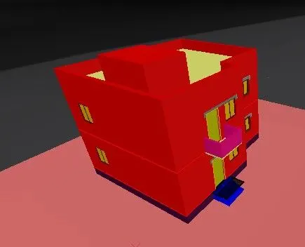
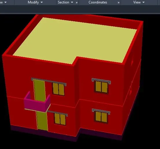
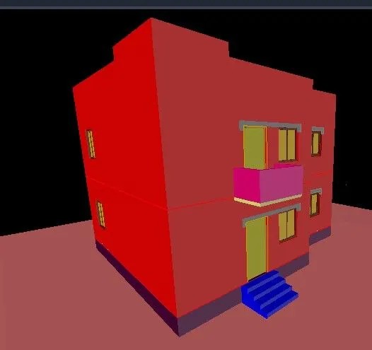
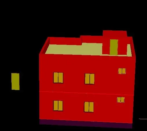
I have Created a 3 dimensional model of the residential building with a rendered view.
Result:
I have Created a 3 dimensional model of the residential building with a rendered view.