Project 2_Creating a 3D rendered model for a Residential Building in AutoCad
AIM : Creating 3D model of the residential building with a rendered view in AutoCAD.
Introduction: In this challenge i have draft the above meationed drawing i.e, Creating 3D model of the residential building with a rendered view in AutoCAD. here in this challange i have attached all the drawings in a image format and with the proper procedure as possible.
The process of creating a mathematical representation of any surface of an object in three dimensions by using special software is called 3D modeling. A 3D model can even be represented as a two-dimensional image by using the 3D rendering process. The user can also create 3D models physically using 3D printers. There is a lot of software that is used to create 3D models like AutoCAD, MAX, MAYA, and many more.
3D models are high in demand with the game developers as well. Some computer games use already rendered images of 3D models, which are known as sprites. This helps the designer to view the model in all directions, and they can make sure that the object created is like the original one.
The comman commands which are used in this challange are discussed below,
Selecting of Tools:
- Line: Ribbon< Home< Line, Command: Line or L, Home< Draw< Line.
- Polyline: Ribbon< Home< Polyine, Command: polyline or pl, Home< Draw< polyline.
- Rectangle: Ribbon< Home< rectangle, Command: rectangle or rec, Home< Draw< rectangle.
- Ploygon: Ribbon< Home< Ploygon, Command: Ploygon or pol, Home< Draw< Ploygon.
- Circle: Ribbon< Home< Circle, Command: Circle or C, Home< Draw< Circle.
- Fillet: Ribbon< Home< Fillet, Command: Fillet or F, Home< modify< Fillet.
- Chamfer: Ribbon< Home< Chamfer, Command: Chamfer or cha, Home< modify<Chamfer.
- Move: Ribbon< Home< move, Command: move or M, Home< modify<Move.
- Copy: Ribbon< Home< Copy, Command: Copy or co, Home< modify<Copy.
- TRIM: Ribbon< Home< trim, Command: TRIM or TR, Home< modify
- 3d Fillet: Ribbon< Home< Fillet, Command: Fillet or F, Home< modify< 3d Fillet.
- 3d Chamfer: Ribbon< Home< Chamfer, Command: Chamfer or 3d cha, Home< modify<3d Chamfer.
- 3d Rotate: Ribbon< Home< Rotate, Command: Rotate or 3ro, Home< modify<3d Rotate.
- Extrude: Location: Draw > Modeling > Extrude.
- Sweep: Location: Draw > Modeling > Sweep.
- Union: Location: Modify > Solids Editing > Union.
- Subtract: Location: Modify > Solids Editing > Subtract.
- Intersect: Location: Modify > Solid Editing > Intersect.
Procedure:
Step-1: Creating plan of Residential Building.
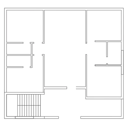
Procedure:
- open autocad 2019 and select a new file and saved as challange 5 and saved in the skill-lync folder.
- set the unit of drawing by giving command un in command and selected Engineering with precion 0'-0.0".
- select limit by giving command limmax and giving the limit 20',20' and entre.
- adjust the dimension size by giving command d and selecting the same unit as mentioned that is Engineering.
- Select the XL command and draft the two lines a vertical and horizontal and interset each other.
- Select the offset option and given the data as shown in the images.
- After giving the proper offset trim the excess.
- Give the command panel and select the trim option and trim the excess.
- creat a plan as shown in the question.
Step-2: Creating of Layers.
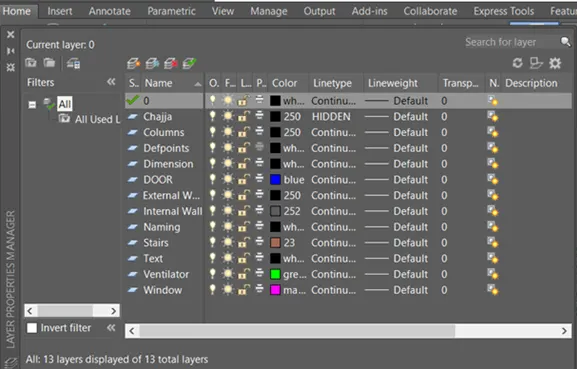
Procedure:
- Go to the ribbon panel select the layers properties
- Select the add new layer option.
- Edit the layer as I have given layer as doors, windows, external wall, internal wall etc..
- cretaing a layer that is go for a option create new layer.
- and now select the layer and right click and select as rename option and give the names.
- the names i have used as Door, window, ventilator wall etc.
- assign proper properties and colour which ever u like.
- Edit the required layers as wanted as shown in the above image.
Step-3: Completion of plan and hatching and placing of doors and windows.
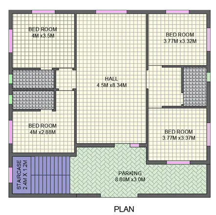
Procedure:
- create a door of size 900, 1000, 750mm of three types as shown.
- draw a line of size 900 and thick it by using ofset and use circle tool as shown.
- trim the excess of the circle and that is how u create a door
- Hatch the created rec by using hatch command and select the concrete hatch with 100 as scale factor.
- Chose the colour in this i have selected black colour.
- Bolock the creted door by using the command block and select the base point and select the component and give the name.
- I have given the name door d1 in this drawing.
- and use copy tool and place the column in the proper position and alignment as shown in the figure.
- simillarly create 2 more doors that is 1000mm and 750mm as shown in figure.
- And give name as D2& D3 respectivilly.
- after creating the doors and windows place it in proper position as shown.
- After placing of doors and window now the time is for naming.
- select the Mtext and select the type of font colour and size of text and type the content what u want to show.
- after creating the prper name copy it by all the places where we want.
- Use move tool and place all the drawings drawn in the proper places.
- use Mtext option and type which ever required or shown.
- after editing the text copy the text and placed in columns or where ever required as shown above.
- edit the copied text by giving commant textedit and star editing the copied text.
- Now give the dimension as shown by using dimlinear command and give proper dimension.
- use dimcontinue option and place it where required.
- and now hatch the walls with using brick wall option and place in proper position.
Step-4: creating and Extruding of walls:
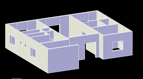
Procedure:
- After completion of plan in 2D now we need to create a 3D model of residential building.
- In order to create a 3D model we need to change the view to the perspective view.
- Now change the view to 2D wire frame so that we can clearly work in 3D.
- Now give the command UCS and select world option in order to create a set UCS as universal.
- Now select the extrude option to create walls.
- Select the walls which are present in the plan and give a height of 3.3 meters.
- For the windows set a height a height of 900mm as sill level and do the same to every wall below the window.
- After completion of extruding the wall now in order to create a wall above window and ventilator following procedure is followed.
- Set UCS to top and use REC command to draw a rectangle at the top edges of the wall around the window.
- Do the same procedure for remaining windows and ventilators.
- Now select all the rectangles above window and ventilators and extrude downward with the height 1.05 meters.
- Now use the command union and union the whole structure.
Step-5: Creating of Doors and Windows in 3D:
Procedure:
Creating of doors windows and ventilators
- In order to create door and windows the following procedure should be followed
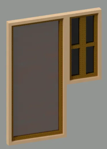
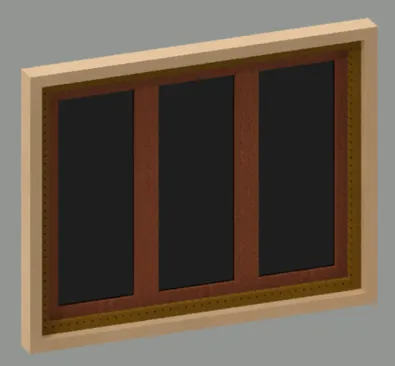
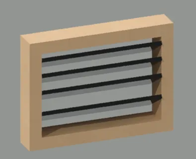
- Set the view as top view and 2D wire frame use REC command and draw a rectangle of size 1.2*1.2 meters respectively.
- Use offset command and give a offset of 50mm internally and again give offset of 100mm internally.
- Now create a panel or glazed panel by using rectangle tool as shown in the figure.
- Now set the view as parallel view and conceptive view.
- Now use press pull command and pres pull the outer rectangle of the window with depth of 100mm.
- Next use same tool and press pull the inner rectangle with a depth of 50mm in order to create a hinge like structure.
- Now or the panels press pull it to 15mm thickness in order to create a glazed like structure.
- Now use MAT in order to give material properties to the window.
- Select auto desk liberally and select wood and apply to the frames of frame members.
- Use the same option select the material glass in the liberally and give it to the glazed panel.
- Now group the frame as well as panel using group option.
Step-6: Placing of Doors and Windows and Finishing of Building:
Procedure:
Placing of lights
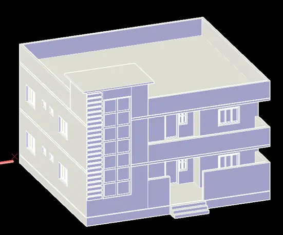
- After completion the model of a residential building now we need to assign the material to the building.
- In order to apply material properties we need to use command MAT in command panel and select auto desk library.
- For walls go to the wall section and give desired colour to the walls of the building.
- Use stones in order to give floor finish like marble to the floor of the building.
- Now the 3D model of residential building is created now the only thing is to render the model.
Step-7: Placing of Lights and Camera in the Position:
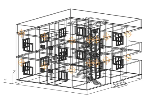
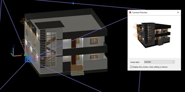
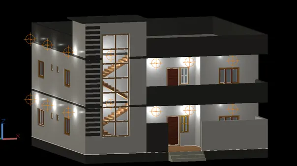
Procedure:
- For rendering we need to give or place the lights in the building for that following procedure is followed.
- Go to the visualize menu on the ribbon panel in which there are many option for rendering purpose.
- Select create light option and in which select lamp option and placed it where ever required.
- Set the intensity to 1 to 5 is recommended as more than 5 intensity create undesired brightness.
- Now after the completion of setting up of lights in the places now the thing left is to create view by placing camera.
- Select create camera option in the visualize tab and set the camera in order to capture the building properly.
- Now set the settings of rendering quality according to your need and specification of PC in which you are working.
- Now click the render option to get the image rendered.
Step-8: Rendered Images.
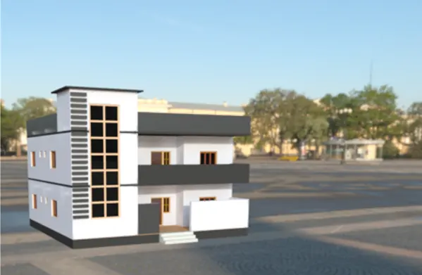
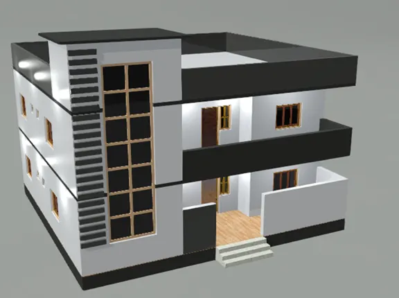
Result:
- In this project the various procedure to create the 3d model of residential building is discussed Clearly.
- The various steps involved in creating and rendering the model is discussed.
- The various Procedure is dicussed during the work.
- The images or rendered images are attached in the project.
------------------------------------------------------E.N.D-----------------------------------------------------------------