Project 2_Creating a 3D rendered model for a Residential Building in AutoCad
AIM: To create a 3D model of a residential building with rendered view in AutoCad using various 3D drafting tools.
PROCEDURE:
- Open a new drawing sheet and set up the drawing units to Metric and decimal.
- Set up the drafting settings
- The available floor plan of a 3BHK residential building with Staircase and Lift is copied to the drawing sheet.
- The residential building of G+1 is considered for creating a 3D model of the building.
- Layers shall be assigned to various items like wall, floor, plinth, doors, windows, parapet,etc. for ease of selection for assigning the material properties.
- The plan is extracted to a floor height of 2900mm
- The windows and door openings are created by providing the wall above the lintel level of 2300mm and the balcony openings are created
- The staircase model for 1 floor is created separately and placed in the 3D model of the building.
- Create the first floor slab by drawing the Polyline for the outer sides of the building excluding the staircase area and lift opening and extruding it to the thickness of slab considered 125mm
- Copy and paste the ground floor walls to the first floor along with the required part of the staircase.
- Again cover the second floor with slab by extruding outer building line excluding stair and lift opening
- Draw parapet above the roof
- Extrude the walls for staircase and lift shaft to create staircase headroom and lift machine shaft.
- Create water tank above the staircase head room and create the manhole openings for water tank.
- Create the window frames with glass and door frame with door leaf as per the door and window openings and place in the openings by grouping the parts of frame and glass
- Extrude the bottom of the building downwards to create the plinth.
- Provide the metal rectangular tubes to cover the toilet ducts
- Go to material browser and select the required materials from the material list.
- Assign the material properties and color to the different solids as per the layer.
- Thus the 3D model of the G+1 residential building is created.
- Various commands and tools like, extrude, sweep, shell, solidedit, material browser, assign material to selction, slice, subtract, etc are used to create the 3D model.
- Create the camera views as required.
- Render the views of camera to required setting using Sky background and lighting setting.
- Various stages during developing of the 3D model are shown below in the screenshots for reference.
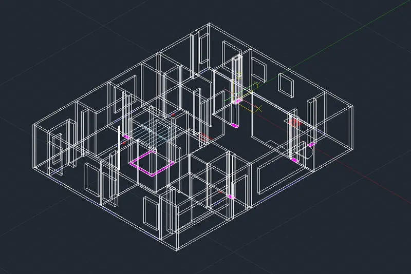
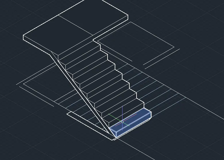
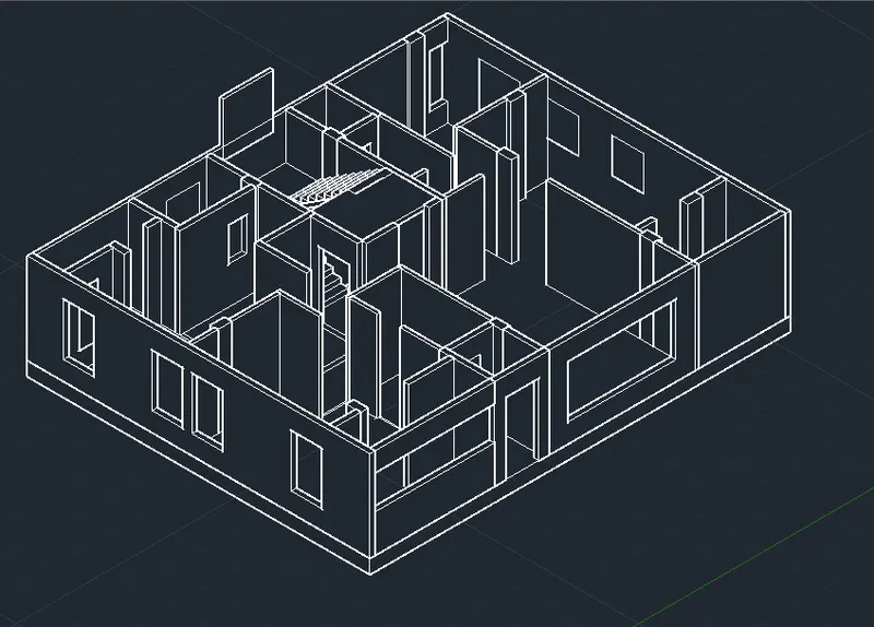
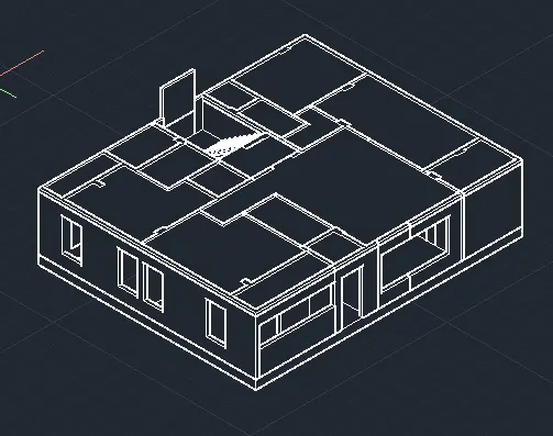
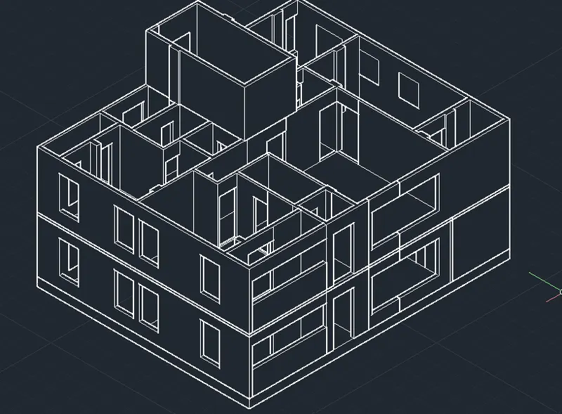
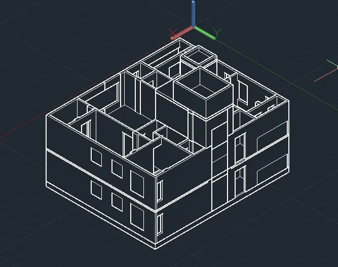
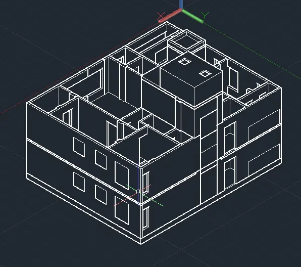
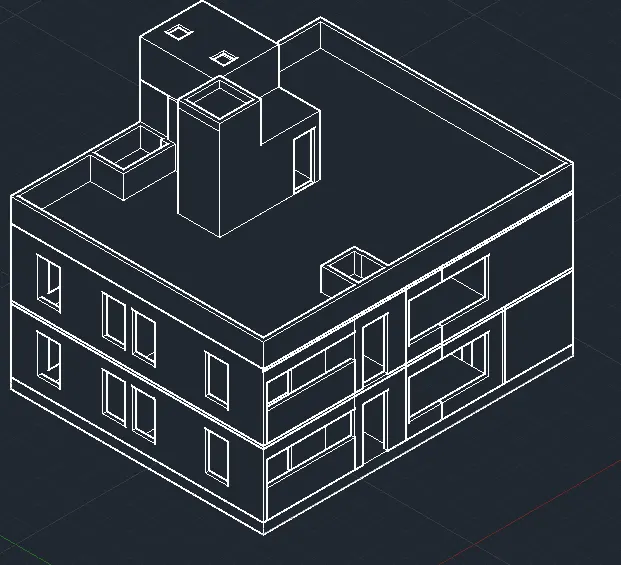
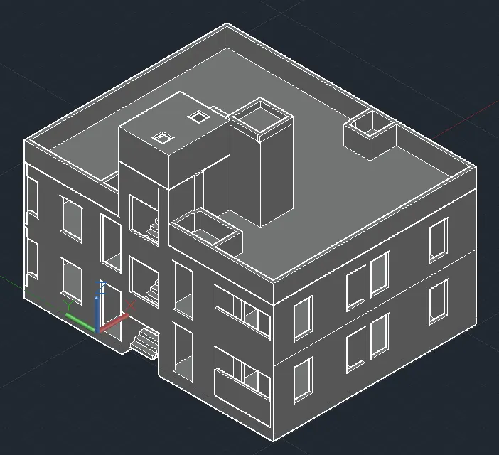
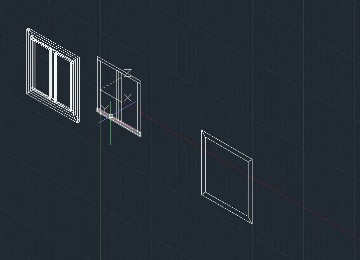
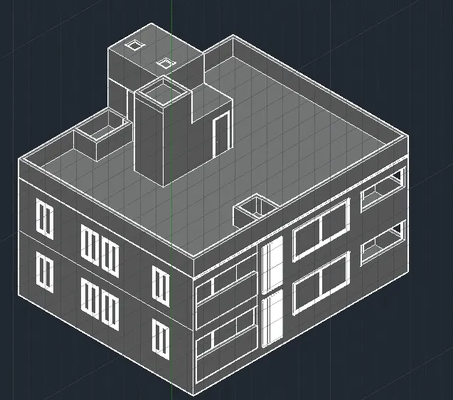
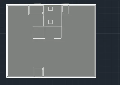
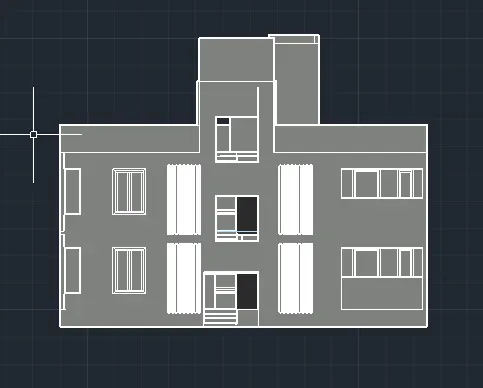
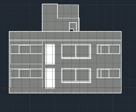
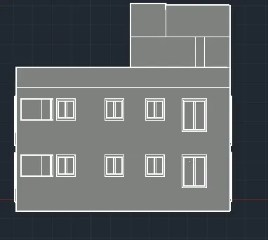
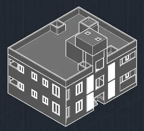
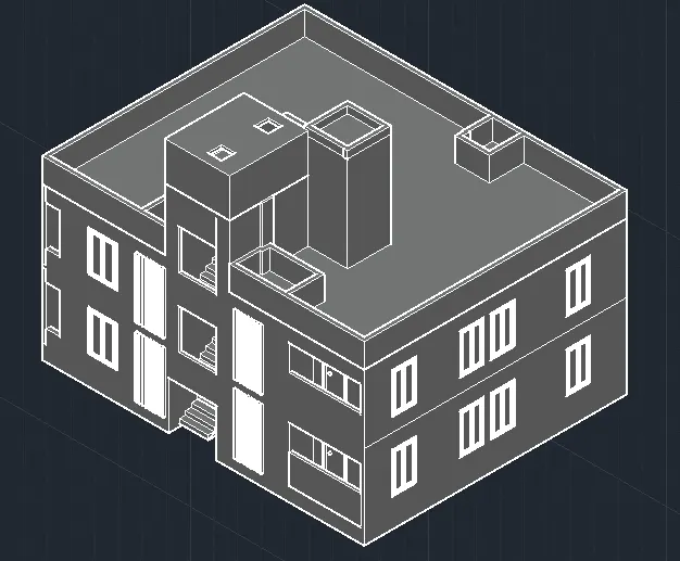
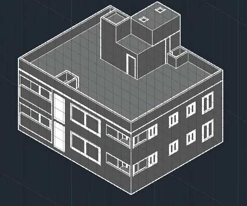
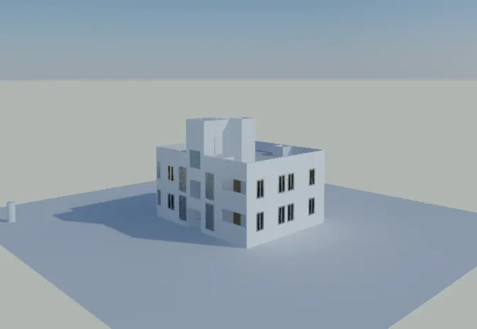
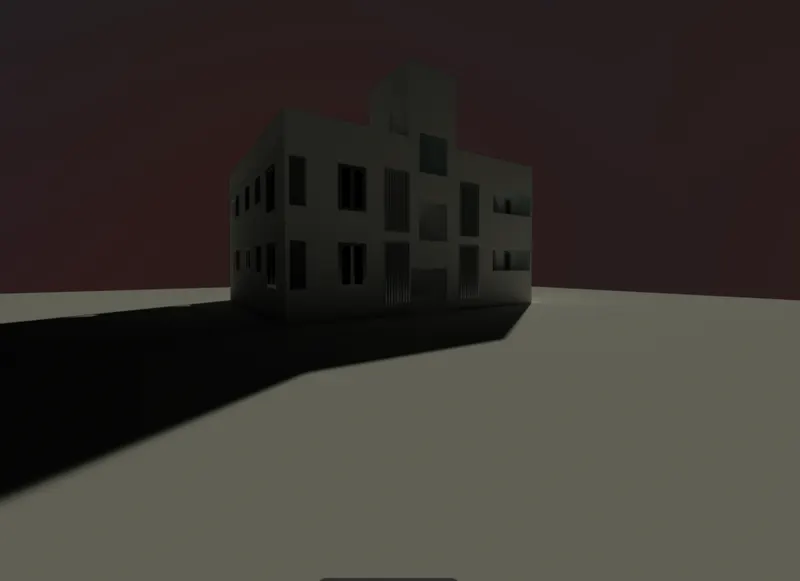
CONCLUSION: Thus we have created a 3D model of the residential building plan using various 3D drafting tools. Since the elevation drawing was not available for the plan, the 3D model is directly created from the plan. The views of camera are taken from different settings and the same are rendered as per the attached screenshots.