Drafting of various geometries using Chamfer, Fillet tool in AutoCad
CHALLENGE 3: Drafting of various geometries given in attachment from 1 to 11 using chamfer, fillet tool in AutoCad.
FIGURE 1:
AIM: To draft the given geometry in the figure 1 of attachment using various tools required to complete the figure in AutoCad.
PROCEDURE:
Set the drawing to Decimal units. Set the drawing limits and zoom.
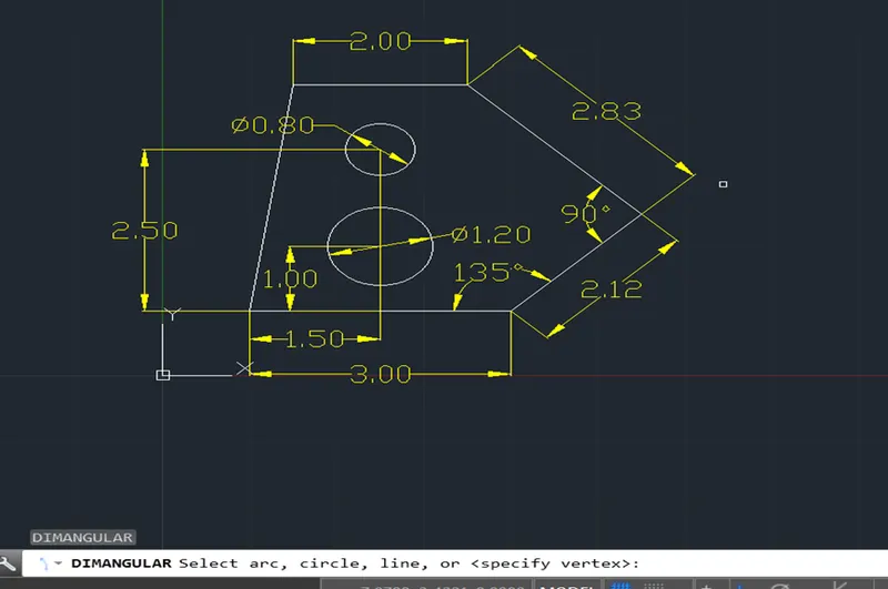
Start with line command (L) with start point as (1,1), draw a line of 3 units towards right.
Continue drawing second line of 2.12 units along the 45-degree angle by entering point (@2.12<45)
Continue drawing second line of 2.83 units along the 135-degree angle by entering point (@2.83<135)
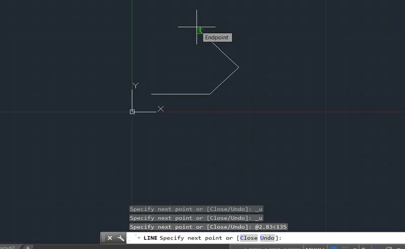
Continue drawing line of 2 units towards left and complete the figure by connecting line to start point.
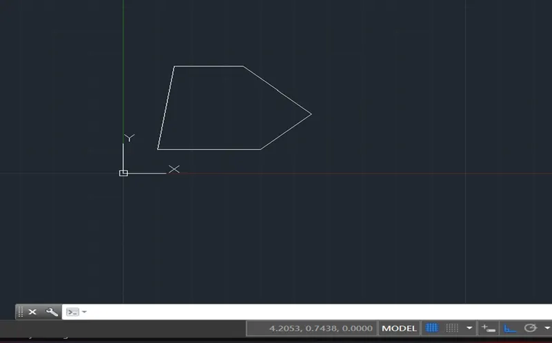
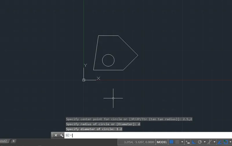
Draw a circle by entering command C and centre point as (2.5,2) and diameter of circle 1.2 units
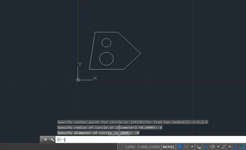
Draw second circle by entering command C and centre point as (2.5,3.5) and diameter of circle 0.8 units
Enter the various dimensions as shown in figure and edit the dimension details of arrow, line text etc. using DimStyle command.
The required final figure is drawn in AutoCad shown in the screenshot below.
CONCLUSION: The required given geometry in the figure is drawn in the AutoCad using various tool and the brief procedure and stage wise screenshots are attached for reference.
FIGURE 2:
AIM: To draft the given geometry in the figure 2 of attachment using various tools required to complete the figure in AutoCad.
PROCEDURE:
Set the drawing to Decimal units, set limits and zoom.
Start with line command (L) with start point (50,50) and draw horizontal line with assumed length of 40 units as reference line.
Continue with line and draw an inclined line of 34 units (for 2’10”=34”) length at 45degree, L(@34<45)
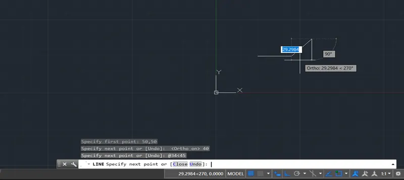
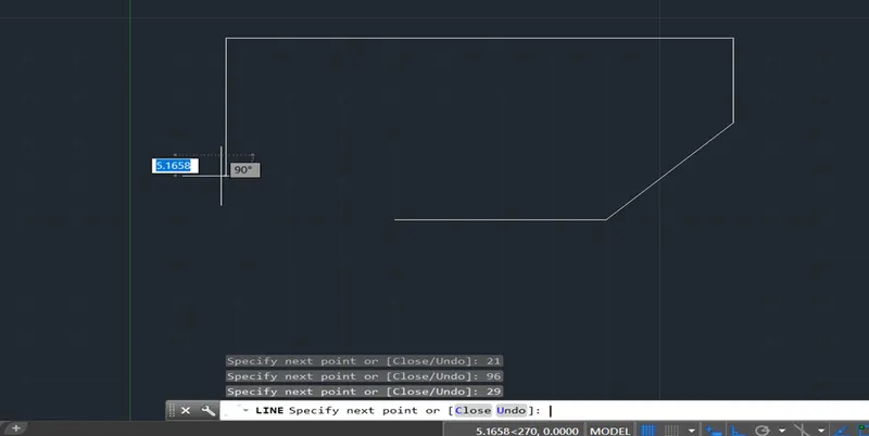
Continue drawing line upward of length 21units (for 1’9”=21”)
Continue to draw horizontal line towards left of length 96 units (for 8’ =96”)
Continue to draw vertical line downwards of length 29 units (for 2’5” =29”)
Now continue to draw a reference horizontal line of 36 units (for 3’ =36”) and reference perpendicular vertical line of 30 units (for 2’6” =30”) and close the horizontal line of 36units and vertical 30 units to form a triangle to for hypotenuse
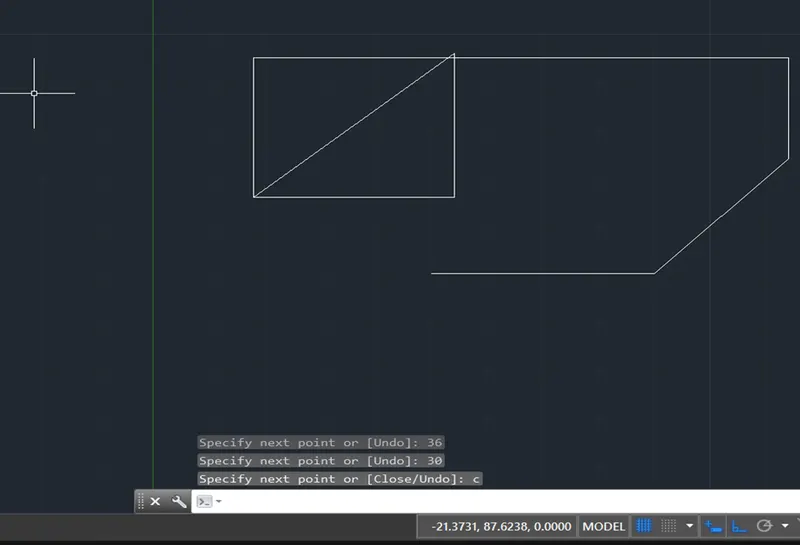
Draw a circle with centre from the node of 36 units line and hypotenuse for a radius of hypotenuse
The circle meets the first reference line of assumed 40 units length as say point A
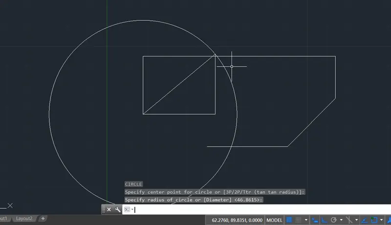
Draw another circle with centre from the node of 36 units line and hypotenuse for a radius of 36 units.
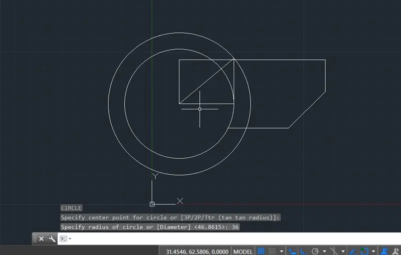
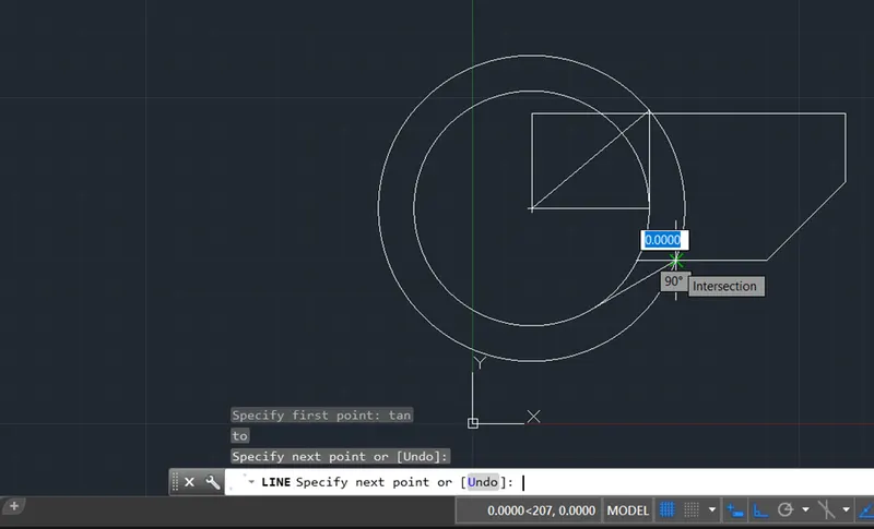
Now draw a tangent line from circle of 36 radius to meet the point A
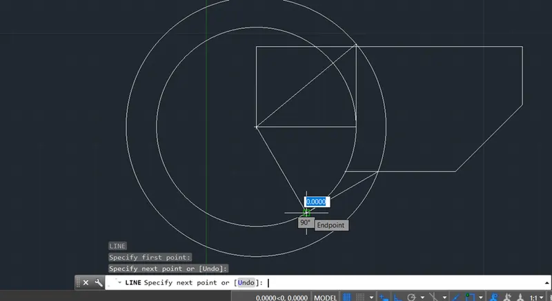
Draw a perpendicular line from the centre of circle to the tangent line meeting circle.
Delete the circles and delete the reference line triangle
Trim the extra line at point A
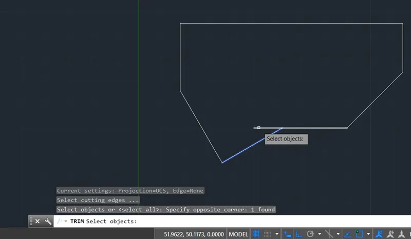
Thus, the required figure is obtained. The stage wise screenshots of the drawings are attached for reference along with the completed drawing with dimensions as per the figure.
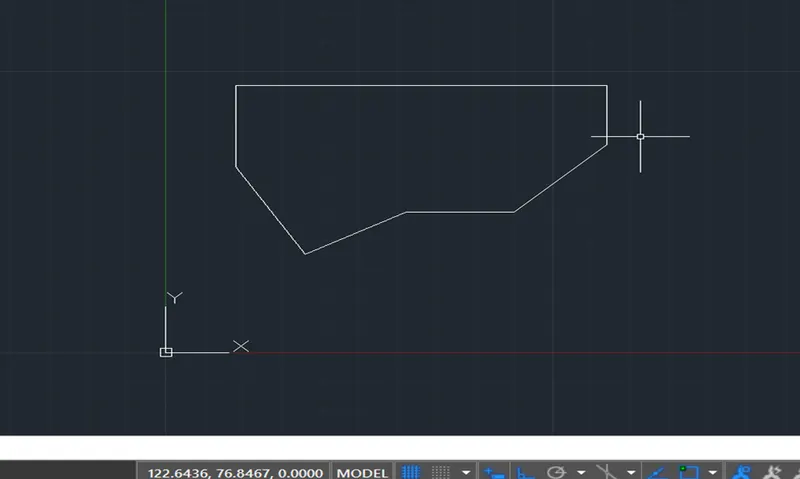
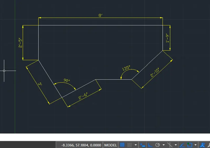
CONCLUSION: The required given geometry in the figure is drawn in the AutoCad using various tool and the brief procedure and stage wise screenshots are attached for reference.
FIGURE 3:
AIM: To draft the given geometry in the figure 3 of attachment using various tools required to complete the figure in AutoCad.
PROCEDURE:
Set the drawings for Engineering units, drawing limits and zoom.
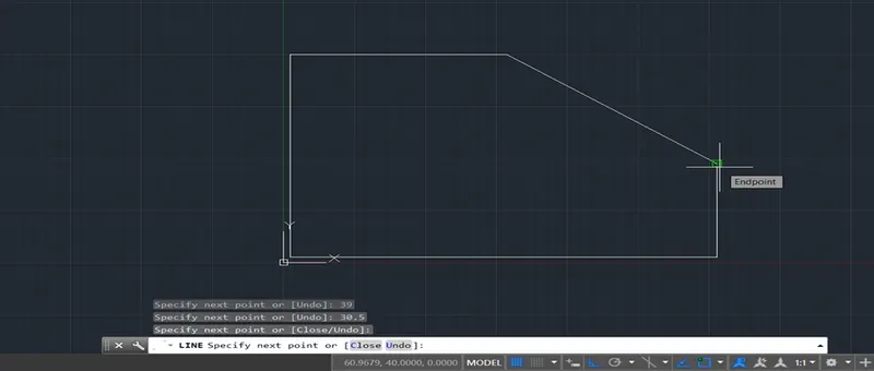
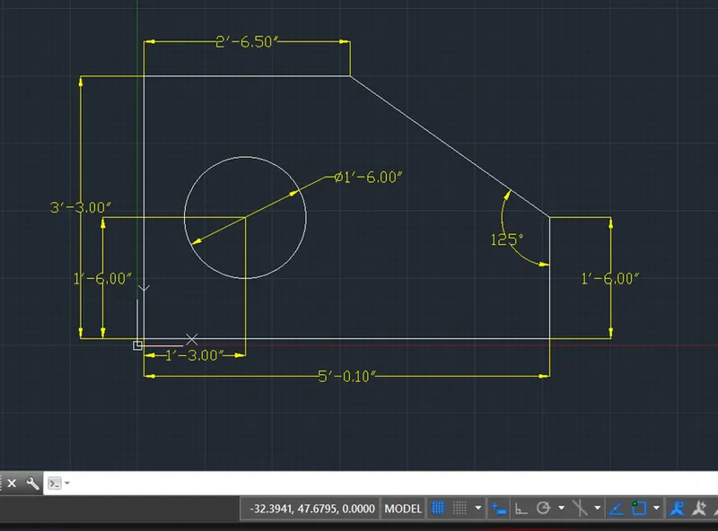
Start with line command L and start point as (1,1) and length of 60.1units (for 5’ 0.1” =60.1”)
Continue line upward for 18 units (1’6” =18”)
Draw vertical line from start point for 39 units (3’3” = 39”)
Continue drawing horizontal line of units 30.5 units (2’6.5” =30.5”)
Then finally join the open ends or figure with line to form a angular line.
Provide the dimensions as shown in figure by setting the dimension style as per drawing requirement.
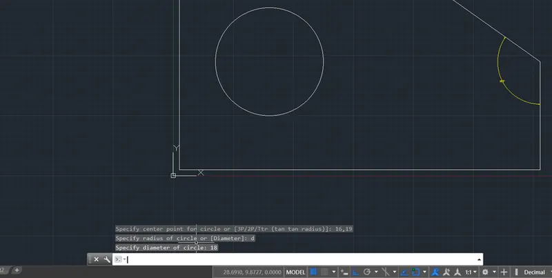
All the stage wise and final screen shots of drawings are attached below.
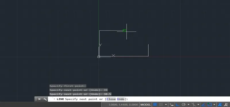
CONCLUSION: The required given geometry in the figure is drawn in the AutoCad using various tool and the brief procedure and stage wise screenshots are attached for reference.
FIGURE 4:
AIM: To draft the given geometry in the figure 4 of attachment using various tools required to complete the figure in AutoCad.
PROCEDURE:
Set the drawing to Decimal units and set up limits and zoom.
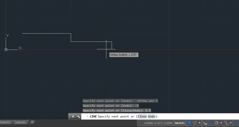
Draw the given figure using line commands in the required directions.
Provide the dimensions for the final drawing as shown in figure and set the dimension style as per drawing requirement.
All the stage wise screenshots of the drawing and final drawing with dimensions are attached below.
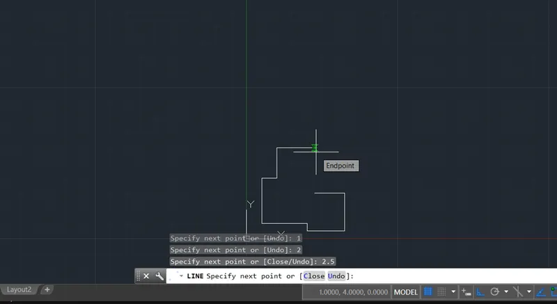
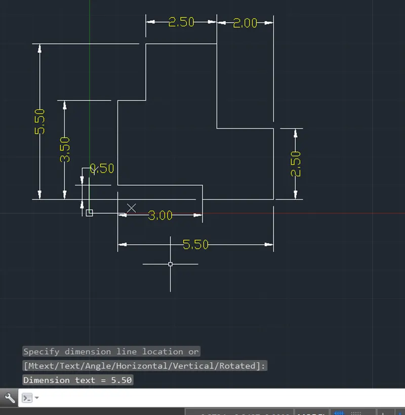
CONCLUSION: The required given geometry in the figure is drawn in the AutoCad using various tool and the brief procedure and stage wise screenshots are attached for reference.
FIGURE 5:
AIM: To draft the given geometry in the figure 5 of attachment using various tools required to complete the figure in AutoCad.
PROCEDURE:
Set the drawing to Decimal units and set limits and zoom.
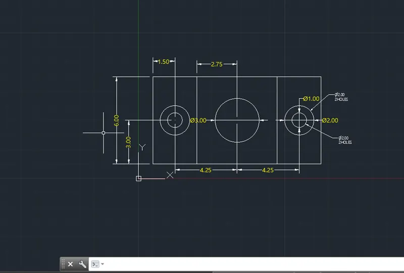
Draw the shown figure using the line commands as per the dimensions given in drawing, alternatively the rectangle can be drawn using RECTANG command for size 11.5 x 6 units.
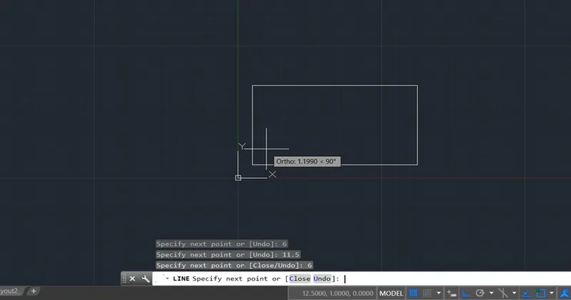
The left line is copied at two locations towards right using OFFSET command for 3 units and 8.5 units
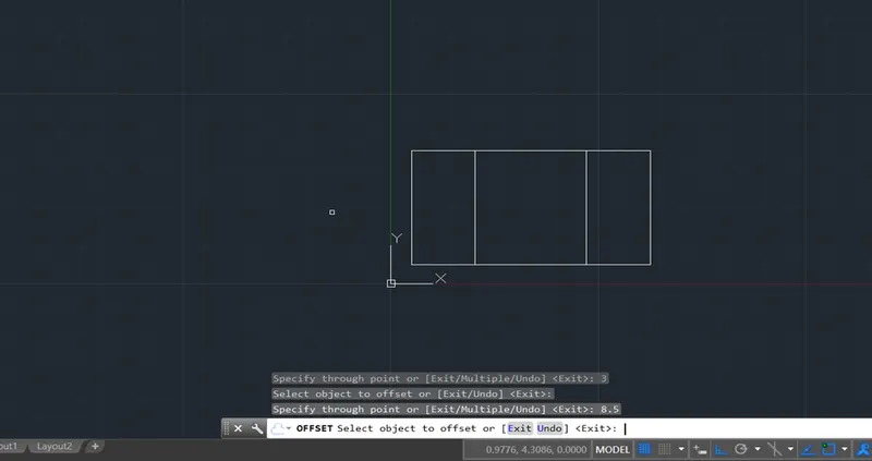
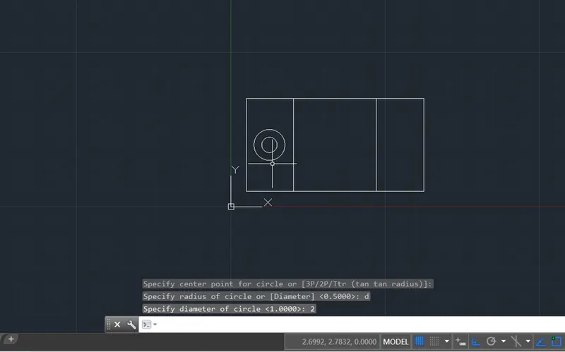
The circle is drawn using the centre point calculated from the given dimensions for 1 unit diameter and 2 units diameter.
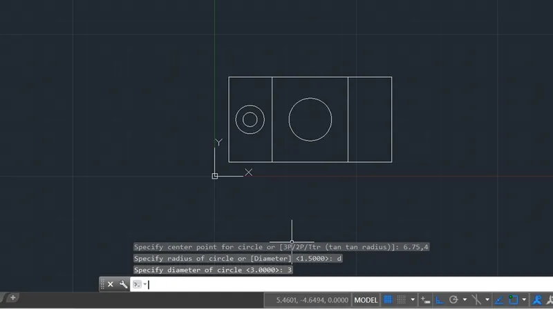
The bigger circle is drawn for diameter of 3 units from centre point calculated from the dimensions given in the figure.
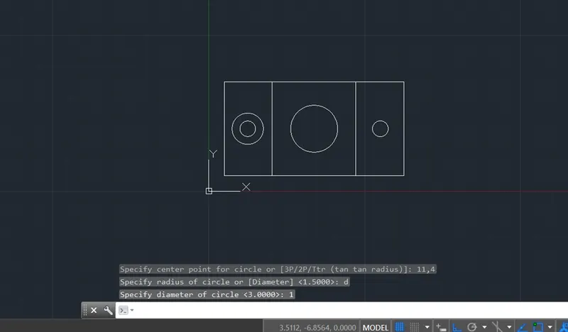
Similarly, the two circles of 1unit diameter and 2 units diameter are drawn on the right side as per the figure using the centre coordinates from given dimensions.
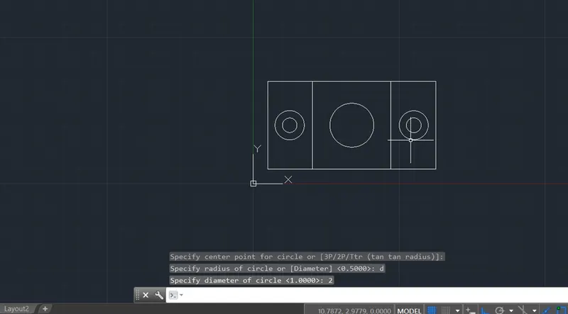
The required figure is drawn.
Provide the dimensions as per the given figure and set the dimension style as required.
CONCLUSION: The required given geometry in the figure is drawn in the AutoCad using various tool and the brief procedure and stage wise screenshots are attached for reference.
FIGURE 6:
AIM: To draft the given geometry in the figure 6 of attachment using various tools required to complete the figure in AutoCad.
PROCEDURE:
Set the drawing for Decimal units and drawing limits and zoom.
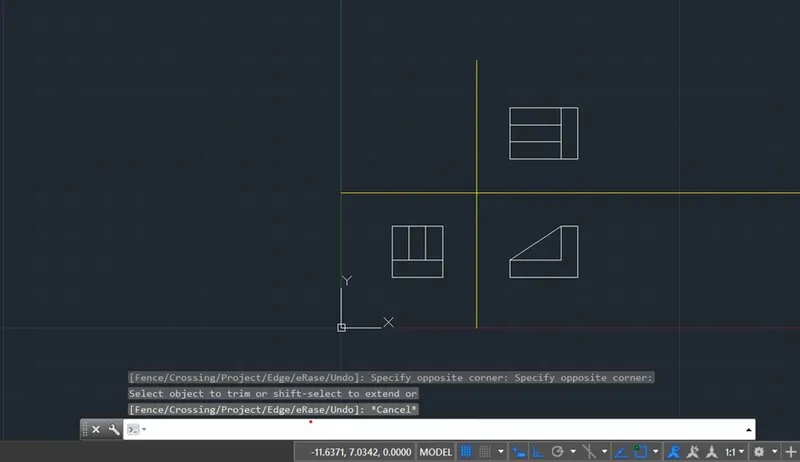
Draw horizontal line and vertical line for reference with centre say (4,4) such that 4 quadrants are formed so that the different views of the given 3 figures can be drawn in 3 quadrants.
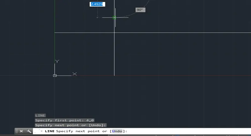
Draw a reference start line 1unit offset from both horizontal line and vertical line on either side.Draw three more vertical lines with offset for 0.5 on left quadrants and horizontal lines at 1.0 units & 1.5 units at lower quadrants and further vertical line offset of 1.5units & 2.0 units on the right quadrants.
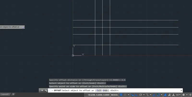
Draw 3 more horizontal lines in upper quadrants at 0.5 unit distance.
Now trim the unwanted lines keeping the required lines as per the figure.
Draw the angular line on lower right quadrant by joining the points for side view as per figure.
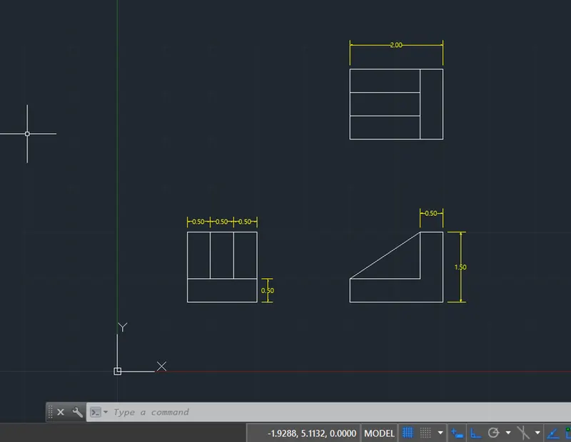
Thus, the Front view is formed in lower left quadrant, side view is formed in the lower right quadrant and top view is formed on right top quadrant.
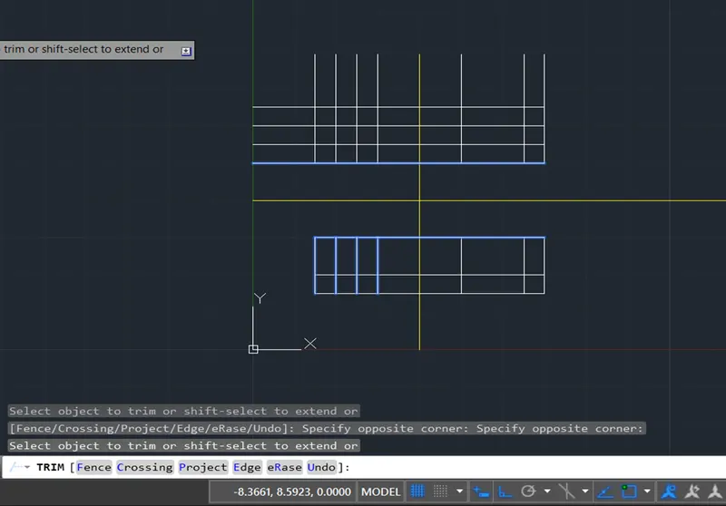
Delete the reference lines.
Required figures are formed.
Provide the dimensions as shown in the figure and set the dimension style as per drawing requirement.
The stage wise screen shots of the drawings and final drawing with dimension as per given figure are attached for reference.
CONCLUSION: The required given geometry in the figure is drawn in the AutoCad using various tool and the brief procedure and stage wise screenshots are attached for reference.
FIGURE 7:
AIM: To draft the given geometry in the figure 7 of attachment using various tools required to complete the figure in AutoCad.
PROCEDURE:
Set the drawing to Decimal units and set limits and zoom.
Start with a line command (L) and start point (1,1) and draw upward vertical line of 100 units
Continue with line command and draw horizontal line towards right of 210 units and further vertical downward line of 75 units
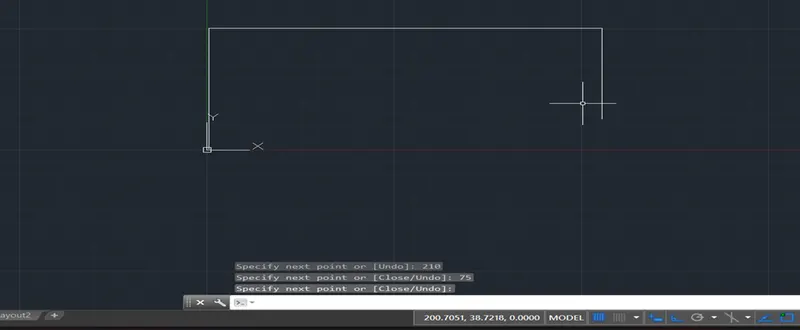
Compute the coordinates of first rectangle for start point and draw a rectangle of length 70 units and width 30 units
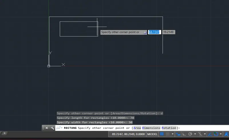
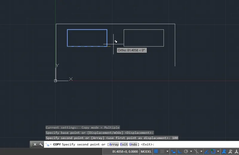
Copy the rectangle with base point and move it by 100 units (70 +30)
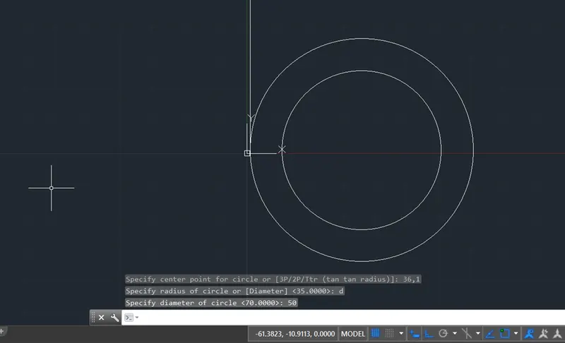
Draw a circle of radius 35 units with centre as (36,1)
Again draw circle of diameter 50 units with same centre.
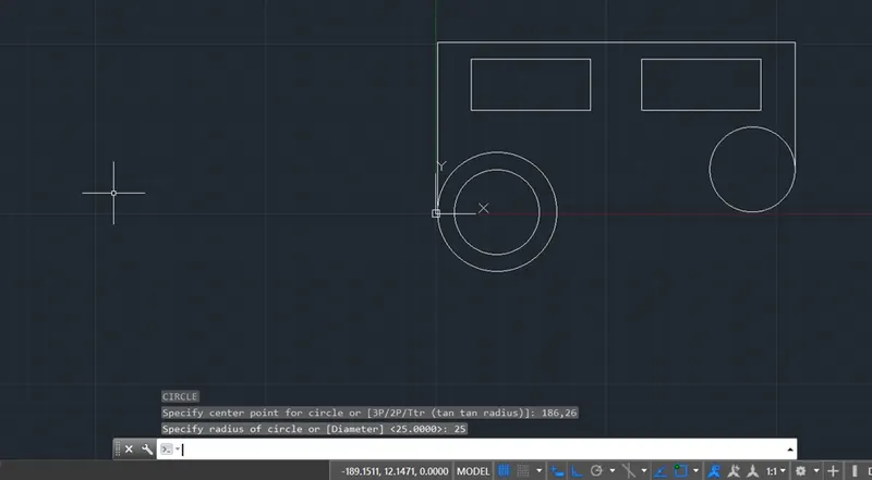
Draw another circle of radius 25 and centre (186,26)
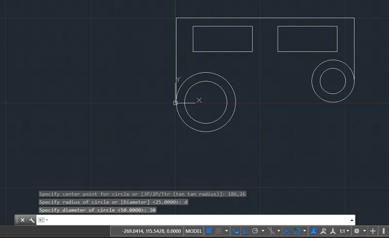
Draw one more circle from same centre of diameter 30 units
Copy the top horizontal line and move 60 units downwards as shown in drawing. Draw a vertical tangent line to the bigger circle of 35 units radius meeting the horizontal line
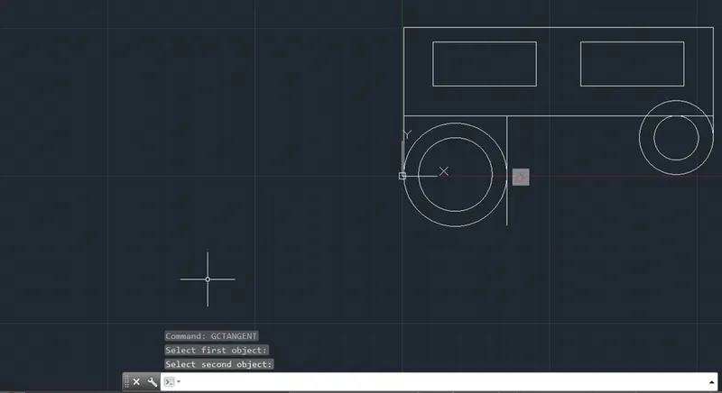
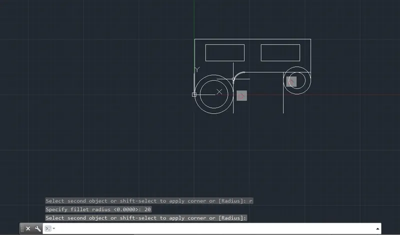
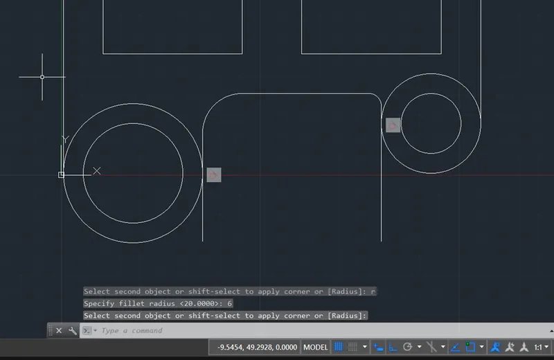
Fillet the tangent line and horizontal line with radius 20 units. Draw a vertical tangent line to the 25 units radius circle to meet the horizontal line and fillet them with 6 units radius
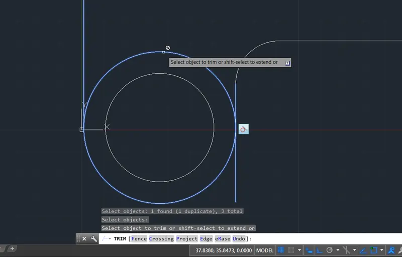
Now trim the bigger circles on both the sides for top portion
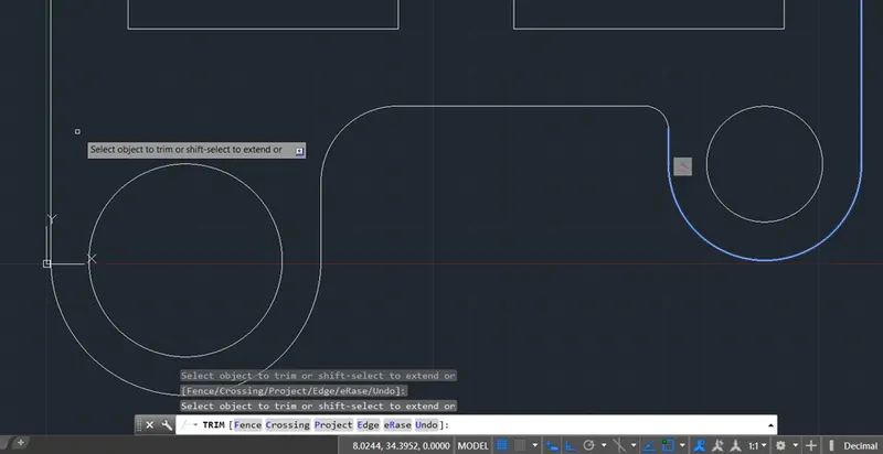
The required figure is obtained.
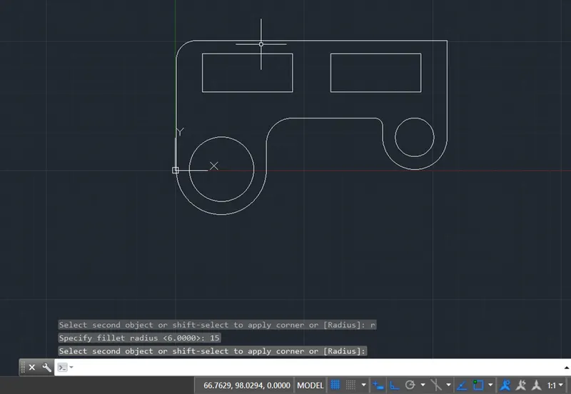
Provide the dimensions as per the attached figure by setting the dimension style as required as per drawing.
The screenshots of various stages are attached for reference.
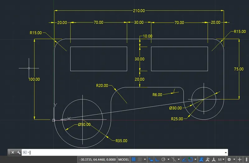
CONCLUSION: The required given geometry in the figure is drawn in the AutoCad using various tool and the brief procedure and stage wise screenshots are attached for reference.
FIGURE 8:
AIM: To draft the given geometry in the figure 8 of attachment using various tools required to complete the figure in AutoCad.
PROCEDURE:
Set the drawing to Decimal units and set limits and zoom.
Draw a circle of diameter 0.9 units with centre (10,10) as start point
Draw another two circles of diameter 4 units and 5 units each with centre of (14.275,10)
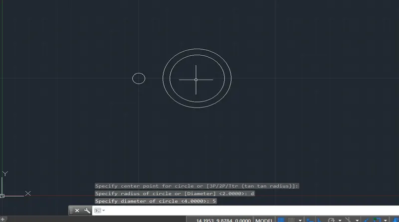
Draw one more circle of 0.9 radius with the centre (10,10) same as small circle
Copy the small circles of 0.9 radius and 0.9 diameter and move through 8.55units.
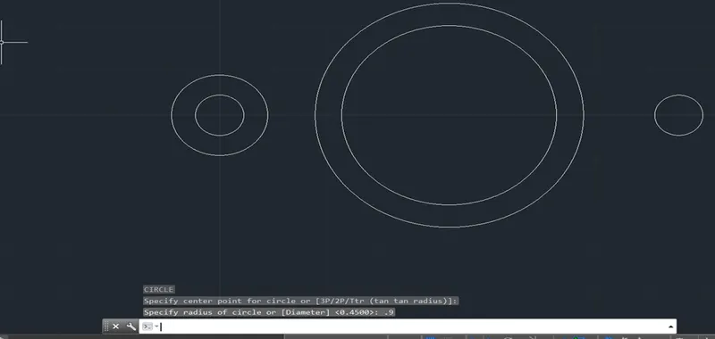
Draw line by command L and enter Tan to command from the smaller circle and Tan to second circle point.
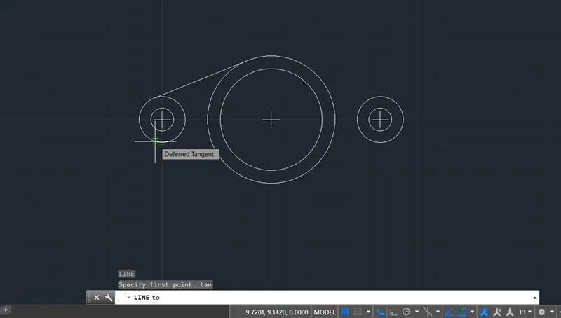
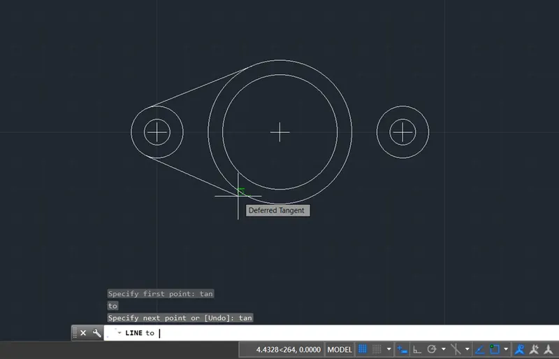
Repeat the Line and Tan to commands to form tangents on other 3 sides as per figure.
Trim the circle of 0.9 unit radius between the tangents.
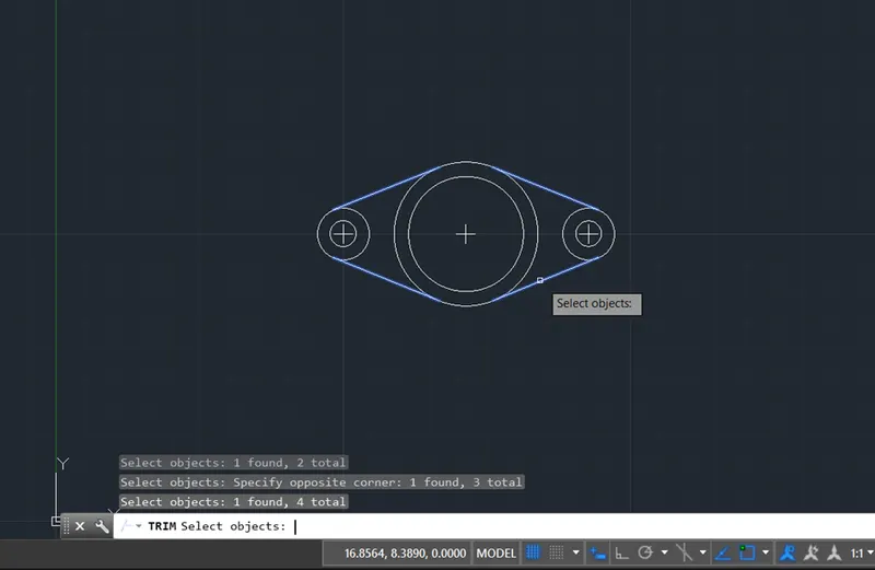
The required geometry as per given figure is obtained.
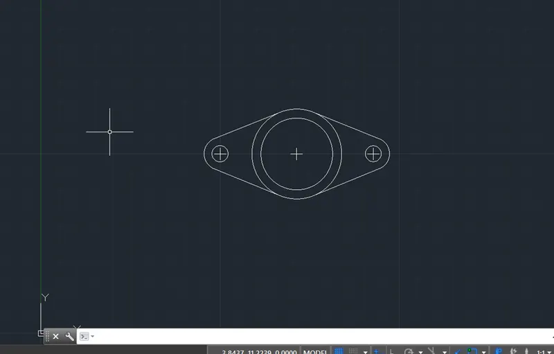
Provide the dimensions to the drawing as per given figure and by setting the Dimension style as per the drawing requirement.
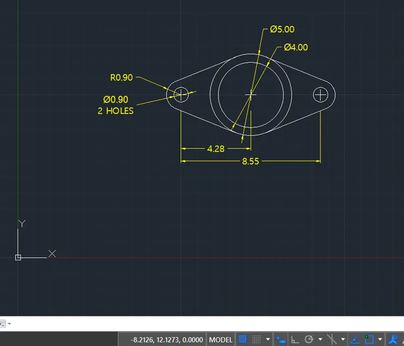
CONCLUSION: The required given geometry in the figure is drawn in the AutoCad using various tools and the brief procedure and stage wise screenshots are attached for reference.
FIGURE 9:
AIM: To draft the given geometry in the figure 9 of attachment using various tools required to complete the figure in AutoCad.
PROCEDURE:
Set the drawing to Engineering units and set limits and zoom.
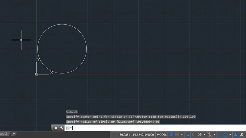
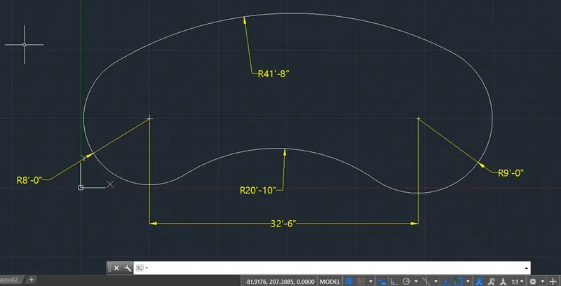
Draw a circle of radius 96 units ( for 8’ = 96”) with the centre (100,100)
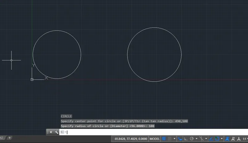
Draw another circle of units 108 (for 9” = 108”) by computing the centre of (190,100)
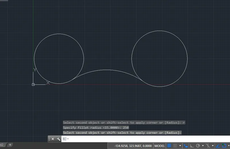
Fillet the bottom part of the circles by using radius of 250 units ( for 12’10” =250”)
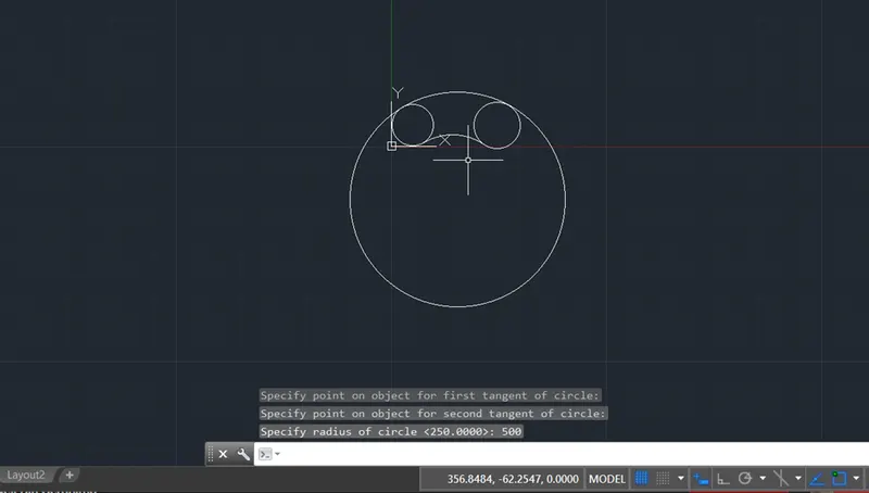
Draw a circle of radius 500 units( for 41’8” =500”) for upper part of circles using Tan Tan Radius command
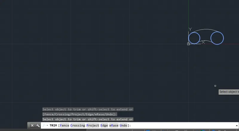
Trim the unwanted part of the big circle by selecting the smaller circles and trimming bigger or lower part of big circle.
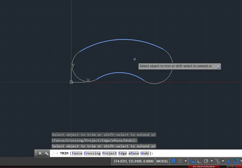
Trim the inner parts of smaller circles by selecting the upper and lower arcs and trimming unwanted inner parts of circle.
The required figure is obtained.
Provide the dimension for the drawings as per the figure and setting the dimension style as per drawing requirement.
CONCLUSION: The required given geometry in the figure is drawn in the AutoCad using various tool and the brief procedure and stage wise screenshots are attached for reference.
FIGURE 10:
AIM: To draft the given geometry in the figure 7 of attachment using various tools required to complete the figure in AutoCad.
PROCEDURE:
Set the drawing limits and zoom.
Draw a square of say 40 units using the rectangle command and with start point (1,1) keeping length as 40 and width as 40.
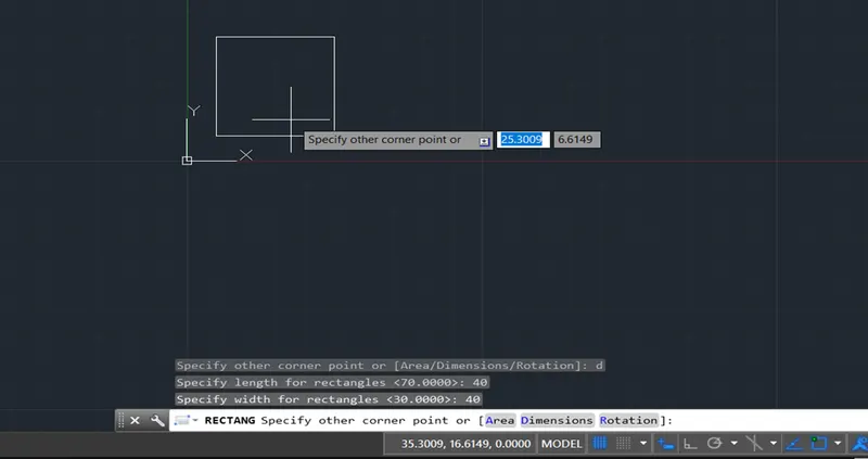
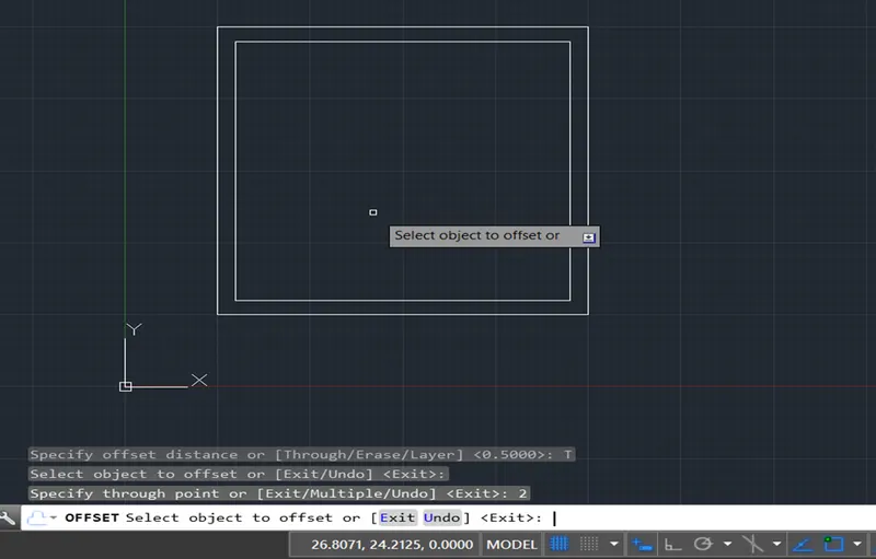
Offset the Square on inner side by 2 units
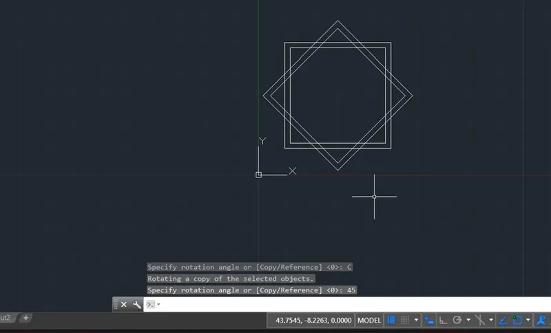
Now select both the squares and rotate by 45 degrees and enter command copy so that required figure is formed.
Trim the internal lines as per the figure to get the required design.
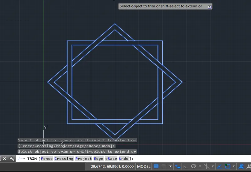
CONCLUSION: The required given geometry in the figure is drawn in the AutoCad using various tool and the brief procedure and stage wise screenshots are attached for reference.
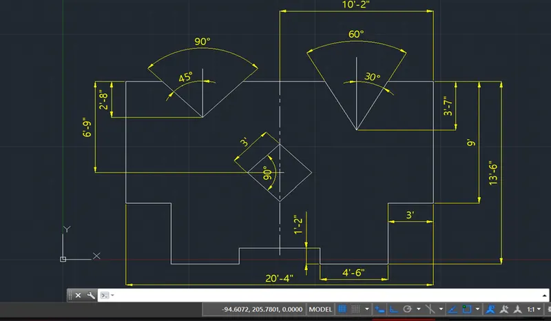
FIGURE 11:
AIM: To draft the given geometry in the figure 7 of attachment using various tools required to complete the figure in AutoCad.
PROCEDURE:
Set the drawing to Engineering units and set limits and zoom.
Draw a line of 36 units (for 3’ = 36”) using start point as (50,50) on right side
Continue line of 54 units (for 4’6” = 54”) downwards and further 54 units on right side
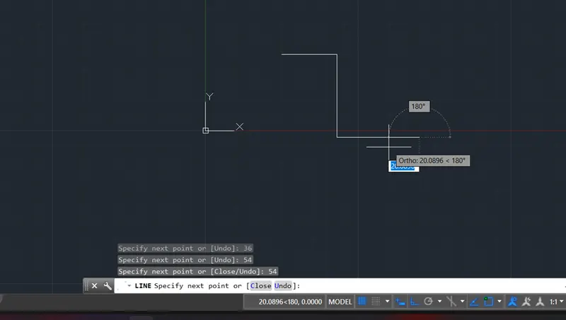
Continue the vertical line upward for 14 units, horizontal line towards right of length 64 units, vertical line downwards for 14 units, horizontal line towards right for 54 units, vertical upwards line for 54 units and horizontal line towards right for 36 units
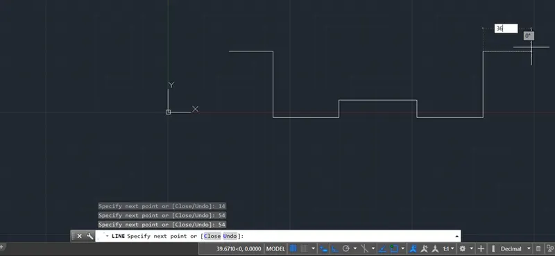
Continue vertical line upwards for 108 units, horizontal line towards left for 244 units and vertical line downwards for 108 units to close the figure.
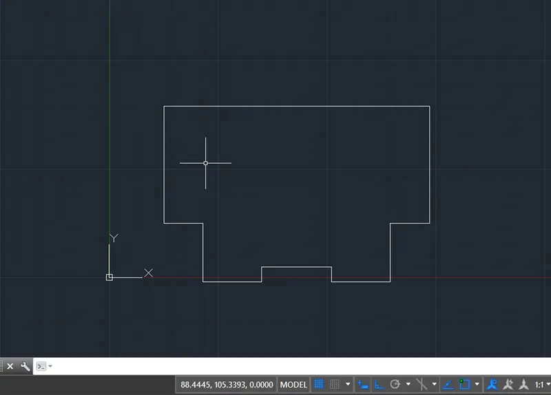
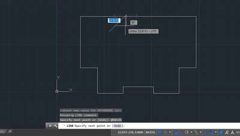
Select point (111,126) for the first conical shape and draw reference inclined line (@50<45) and other inclined line (@50<135) to form the conical shape.
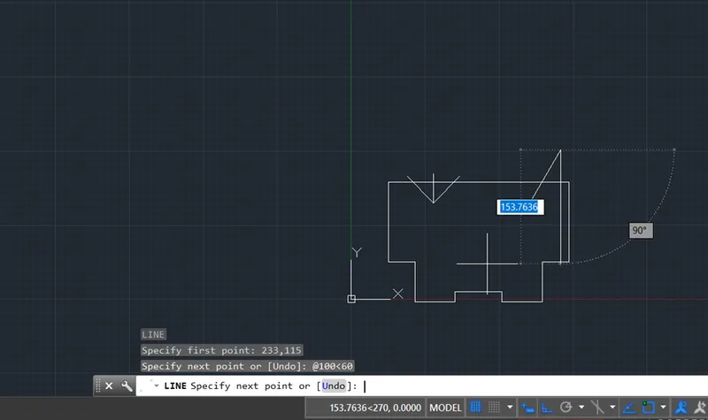
Similarly Select point (233,115) for the second conical shape and draw reference inclined line (@100<60) and other inclined line (@100<120) to form the conical shape.
Draw reference vertical lines upward from centres of the conical shapes
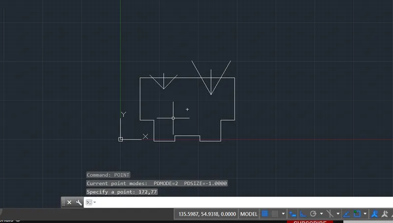
Mark the centre point for the tilted square at (172,77)
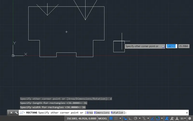
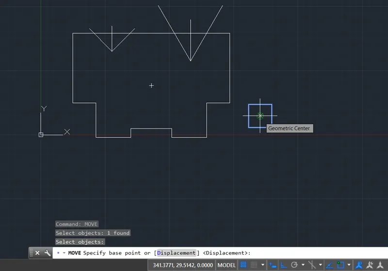
Draw a square of 36 units side outside at random location using Rectang command
Move the square with base point as geometric centre and place it on the centre point of square marked in the drawing
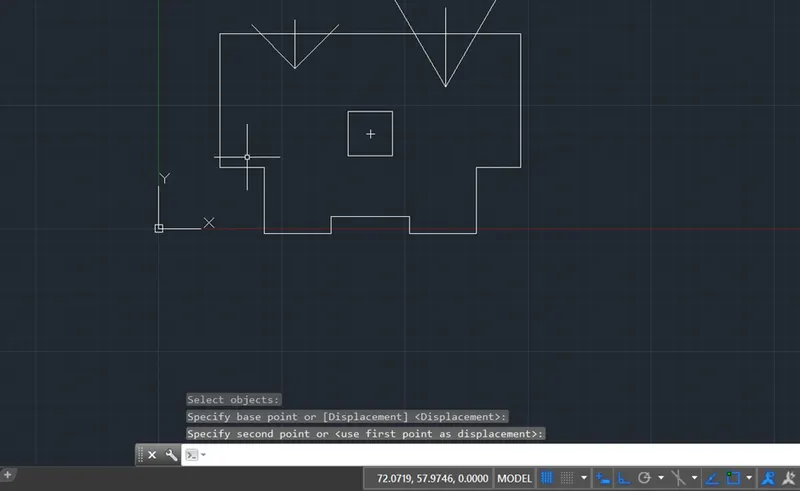
Rotate the square by 45 degrees with base point as geometric centre of square.
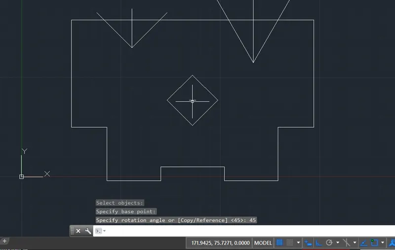
Trim the unwanted lines of the conical shape as per the figure.
The required drawing as per the given figure is obtained.
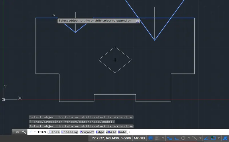
Provide dimensions to the drawing as per the figure by adjusting the dimension style as per drawing requirement
CONCLUSION: The required given geometry in the figure is drawn in the AutoCad using various tool and the brief procedure and stage wise screenshots are attached for reference.