Creating a Floor plan, Footing detail and Isometric view using AutoCad
FIGURE C1
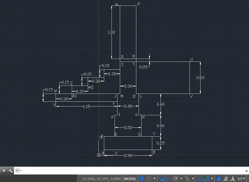
AIM: To draw the cross section of load bearing wall over spread footing and steps as shown in figure of attachment C1.
Below is the final figure drawn to refer the point A, B, C… etc as mentioned in the procedure followed
PROCEDURE:
Open new drawing. Quickset up the drawings to Metric system.
Open Drafting setting command and switch on the grid set X spacing 1 & Y spacing 1 Major line every 10 units.
Enter command Rect (rectangle)
Start point 1,1 say point A
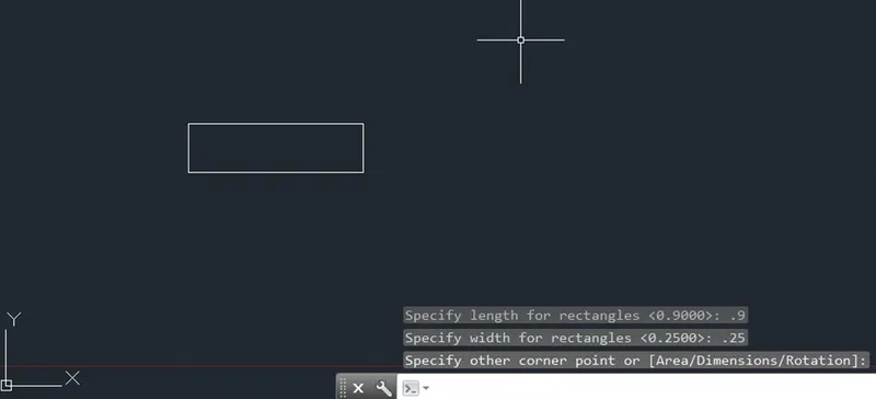
Enter D (dimensions). Length as 0.9 and width 0.25.
Enter second corner on upper right side to form a rectangle of 0.9 x 0.25. Rectangle ABCD
Command L (line)
Move the cursor to left top corner of rectangle point B and click for first point
Move the cursor upwards (towards 90degree). Ortho mode is on.
Type 0.4 (dimension of line) and press Enter to form vertical line of 0.4 Line BF.
Select the vertical line and enter Move command. Select bottom point B as first point.
Move the line towards right (towards 00 degree) and Type 0.2 displacement and press Enter, the vertical line is moved by 0.2 to point E forming vertical line EF
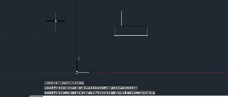
Similarly draw a line on right corner and move the line towards left (towards 180 degree) by 0.2 to form a vertical line GH.
Now type L (line) command and select the first point F on top of 0.4 left vertical line EF, move the cursor towards right (towards 00 degree) and type 0.05, press Enter and horizontal line FI of 0.05 is formed. Further mover cursor upwards (towards 90 degree) and enter 0.4 to form a vertical line IJ of 0.4.
Similarly draw horizontal line of 0.05 from point H on vertical line GH towards left (towards 180 degree) to form horizontal line HK and continue to form one more vertical 0.4 line KL.
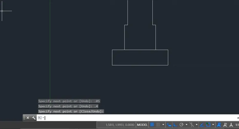
Again, draw the horizontal line of 0.05 from both sides JM & OL from top of vertical lines IJ & KL and continue to draw 1.65 vertical lines MN & OP
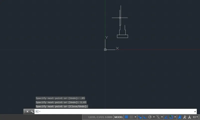
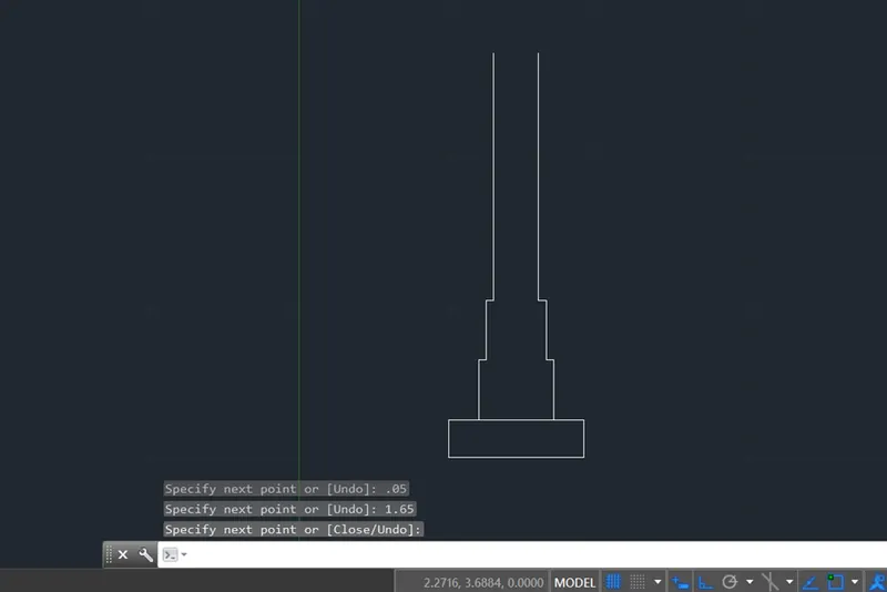
Then close the upper lines by drawing horizontal lines by L (line) command and first point N and second point at P to form line NP
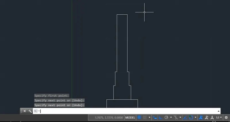
Type OFFSET command and click Through then select the top horizontal line NP and move downwards (towards 270 degree) and type 1.00 and press Enter to form line QR. Further select same top line for offset and through distance of 1.05 downwards (towards 270 degree) to form line ST. Click on exit
Enter command L (line) choose first point T and enter distance 1.00 towards right (towards 00 degree) to form line TU and continue downward line (towards 270 degree) to form line UV and continue line towards left (towards 180 degree) to form line VL
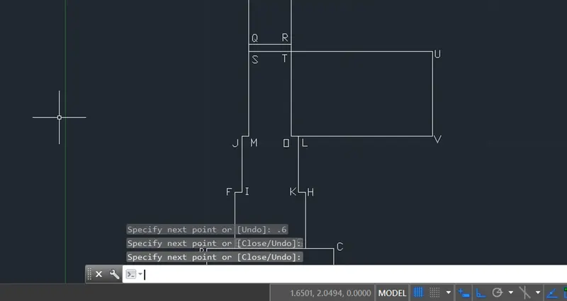
Select point J and type command L (line) and draw a line of dimension 1.15 towards left (towards 180 degree) to form horizontal line JW
Then enter command OFFSET and select line JW and click Through and enter dimension 0.15 to form a line XY.
By using L (line) command join points WX to form vertical line
Draw a vertical line WZ of dimension 0.15 upward from point W using L (line) command
Move the vertical line WZ by using move command by distance 0.3 to form line Z A1
Draw horizontal line from point Z towards right (towards 00 degree) of distance 0.3 to from line Z A2
Now enter Move command, select lines Z A1 & Z A2 and press enter, Click on Array and select first point as A1 and enter number of items as 3 and then select second point A2. Press enter.
The 3 steps will be formed.
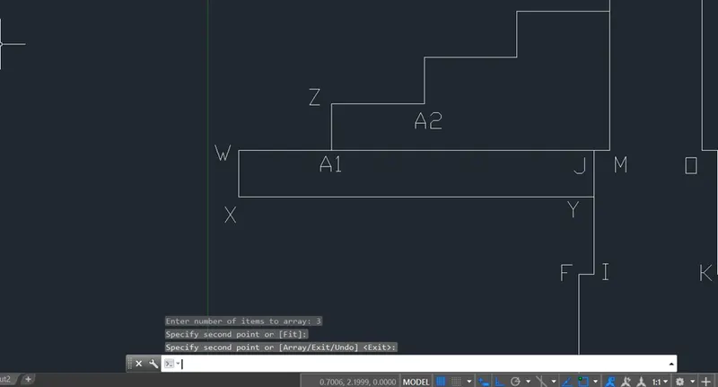
Next step show dimensions.
Enter Dimlinear command select first point A and second point D. Pull the dimension line in required position and press enter.
To adjust the dimension line and dimension text enter command DimStyle
Set the arrows, lines, text size, style and positions as required.
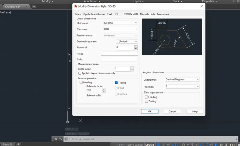
The required Figure is drawn as below.
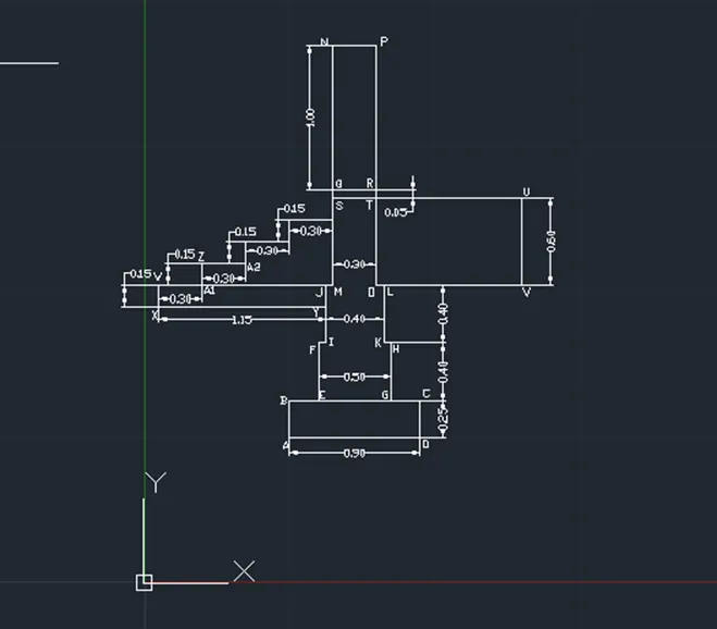
The drawing can be further scaled by using SC (scale) command.
Then select base point and enter scale factor say 10.
The drawing is scaled up by 10 times
The dimensions are also changed. To retain dimension, go to DimStyle and edit the arrows and text as per requirement.
Also enter the scale for dimension as 0.1 in order to maintain actual require dimension.
Below is the scaled figure as required.
CONCLUSION: Thus, we have drawn the given cross section of load bearing wall over spread footing as per the given sketch in C1 using various commands illustrated in attached screenshots and procedure.
FIGURE C2
AIM: To draw the cross section of isolated footing shown in figure of attachment C2.
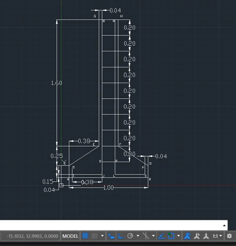
PROCEDURE:
Draw a line AB using line command (L) with start point A (1,1) and distance 1.00
Draw vertical lines of distance 0.25 AC & BD at Point A & B respectively
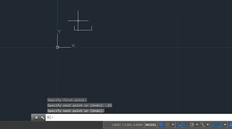
Draw a line starting from point C and to point E with relative coordinate (0.38,0.25)
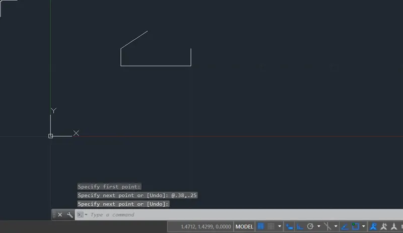
Draw a line starting from point D and to point F with relative coordinate (-0.38,0.25)
Draw vertical lines of distance 1.60 EG & FH at Point G & H respectively
Draw a line joining points G & H
Draw a line IJ with start point (1.04,1.04) and distance 0.38 towards right (towards 00 degree)
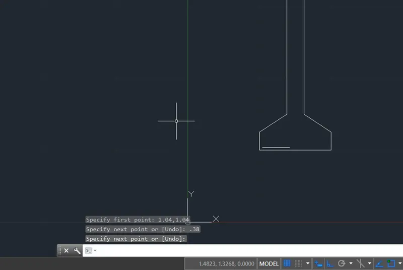
Draw a line KL with start point (1.96,1.04) and distance 0.38 towards left (towards 180 degree)
Draw vertical lines JM & LN starting from Point J & L respectively and touching the line GH
Draw vertical lines IO & KP of 0.07 distance from points I & K respectively
Draw horizontal line joining points J& L
Move the line JL upwards (towards 90 degree) by 0.16 to point Q & R to form a line QR
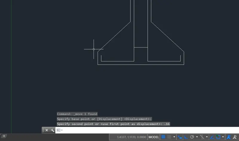
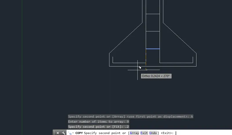
Copy the line QR, select base point Q and enter Array, enter number of items 9 and enter displacement 0.2. to form the stirrups at 0.2 spacing throughout the height of column
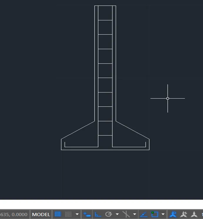
Scale the drawing to scale factor 10 for a larger view.
Modify the dimension arrow, scale, text etc by command DimStyle.
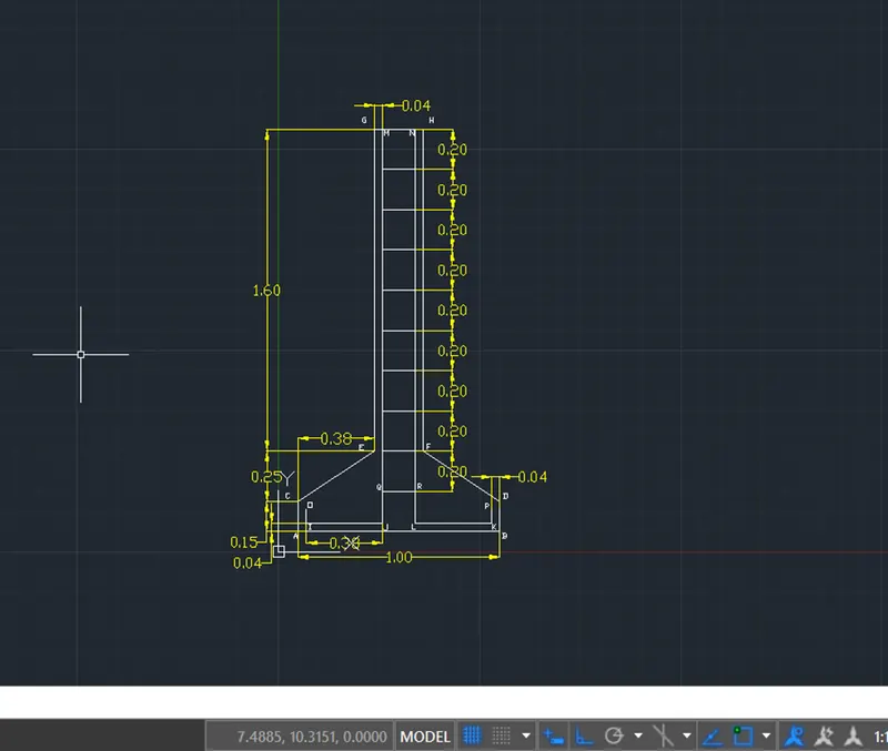
CONCLUSION: Thus, we have drawn the given cross section of isolated footing as per the given sketch in C2 using various commands illustrated in attached screenshots and procedure.
FIGURE C3
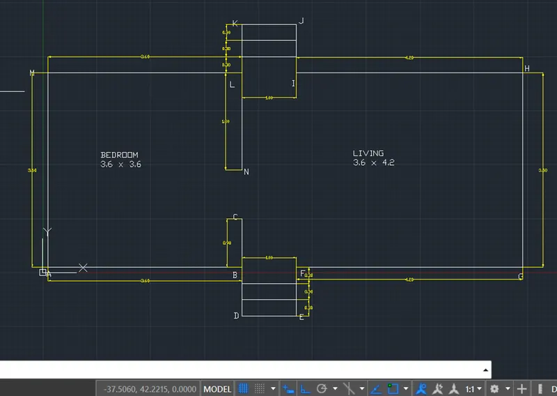
AIM: To draw the Line diagram of a Two Bedroom Building shown in figure of attachment C3.
PROCEDURE:
Draw a line from Point A (1,1) to point B for length of 3.60
Draw vertical line BC of distance 0.90 upwards (towards 90 degree) from point B and vertical line BD of distance 0.90 downwards (towards 270 degree) from point B
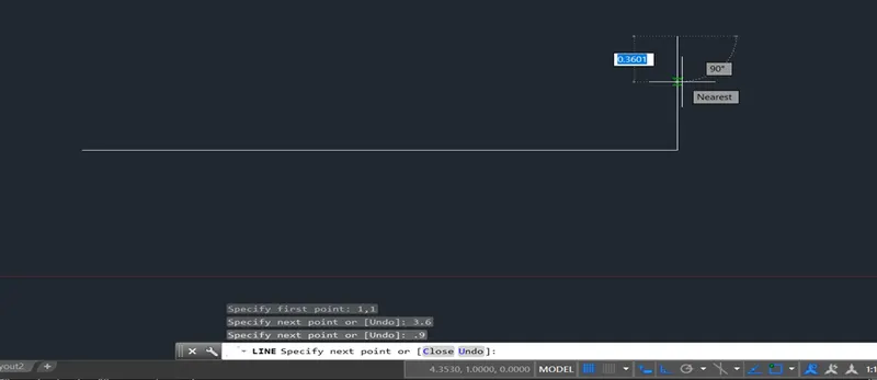
Draw a horizontal line of 1.00 from point D to point E and vertical line from point E to point F
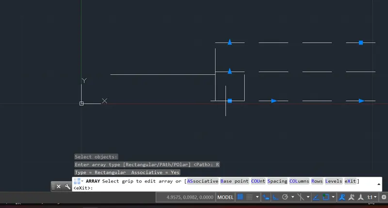
Enter command Array for drawing the steps.
Select line DE for array.
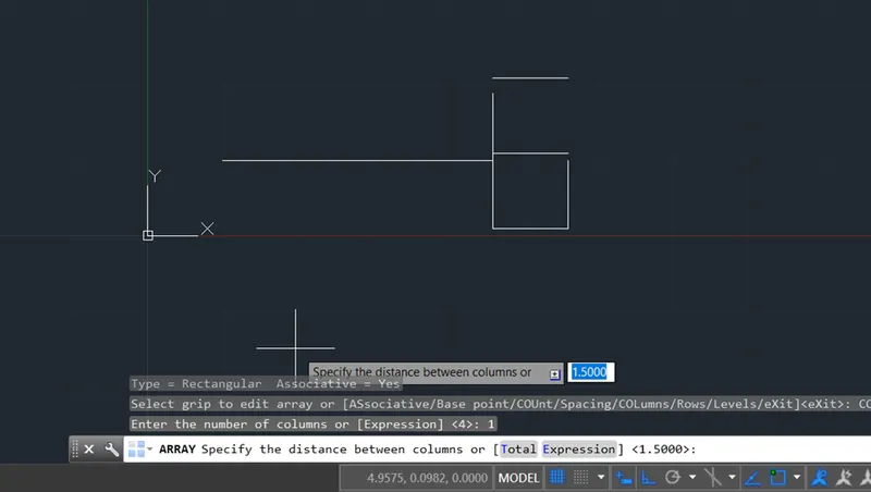
Select the Columns and enter 1 for number columns and enter spacing 1 for columns
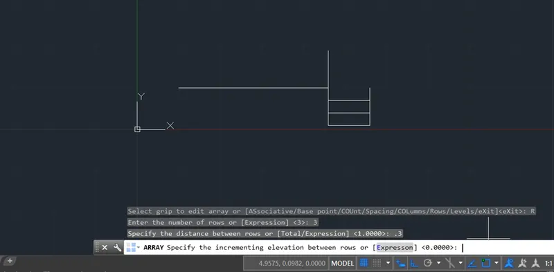
Select the Rows and enter 3 for number of rows and enter spacing 0.3
The 3 steps of 0.3 are formed.
Draw horizontal line F to G of length 4.20 towards right (towards 00 degree)
Draw vertical line G to H of length 3.60 upwards (towards 90 degree)
Draw horizontal line H to I of length 4.20 towards left (towards 180 degree)
Draw vertical line IJ of distance 0.90 upwards (towards 90 degree) from point I and horizontal line JK towards left (towards 180 degree) for length 1.00
Draw vertical line KL of distance 0.90 downwards (towards 270 degree) from point K and horizontal line LM towards left (towards 180 degree) for length of 3.60
Join line MA
Draw a vertical line KL from point K downwards (towards 270 degree) for a length of 1.80
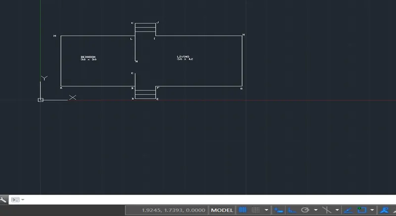
Scale the drawing for larger view to scale factor of 10 .
Set the dimension scale, size, style etc using DIMSTY command.
Enter the Multiline text for the room names and size.
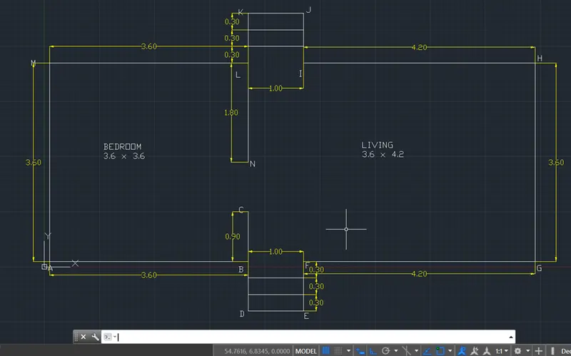
CONCLUSION: Thus, we have drawn the Line diagram of Two Bedroom Building as per the given sketch in C3 using various commands illustrated in attached screenshots and procedure.
FIGURE C4
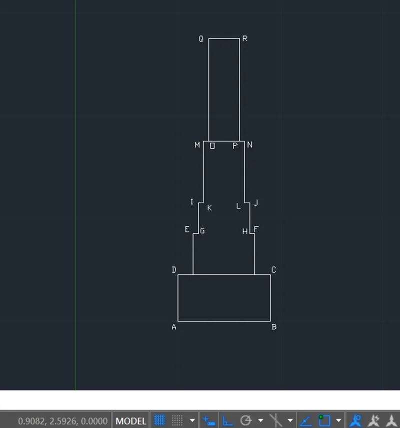
AIM: To draw the Cross Section of Load bearing wall showing foundation details as shown in figure of attachment C4.
PROCEDURE:
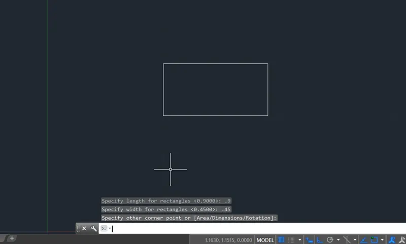
Enter command Rect (rectangle)
Start point 1,1 say point A
Enter D (dimensions). Length as 0.9 and width 0.45.
Enter second corner on upper right side to form a rectangle of 0.9 x 0.45. Rectangle ABCD
Draw a vertical line DE of length 0.4 upwards (towards 90 degree)
Move the line DE by 0.15 towards right say D’E
Offset the line D’E by 0.6 towards right to form line say C’F
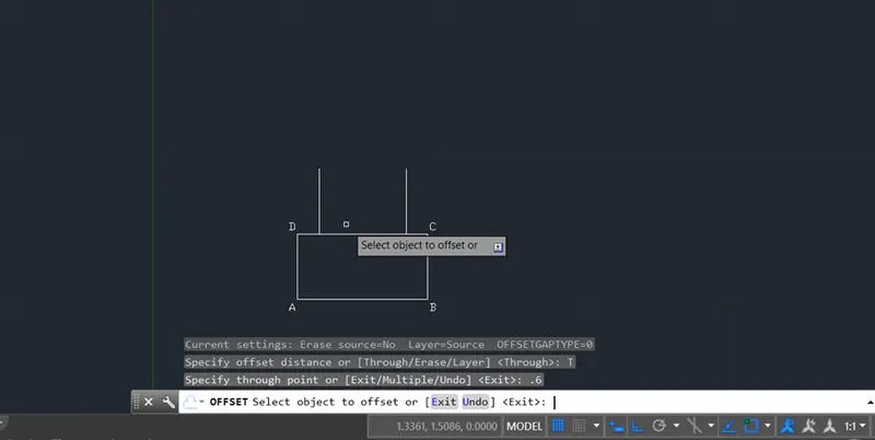
Draw a horizontal line EG of 0.05 from point E towards right and line FH of 0.05 from point F towards left
Draw vertical lines GI & HJ of 0.3 from point G & H respectively
Draw a horizontal line IK of 0.05 from point I towards right and line JL of 0.05 from point J towards left
Draw vertical lines KM & LN of 0.6 from point K & M respectively
Join point M & N by line command
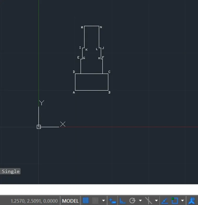
Draw a vertical line MQ of length 1.00 upwards (towards 90 degree)
Move the line MQ by 0.5 towards right say OQ
Offset the line OQ by 0.3 towards right to form line say PR
Join point Q & R by line command
The required figure is drawn. Scale up the drawing for larger view by scale factor 10.
Set the dimension scale, line, text etc as required with DIMSTY command.
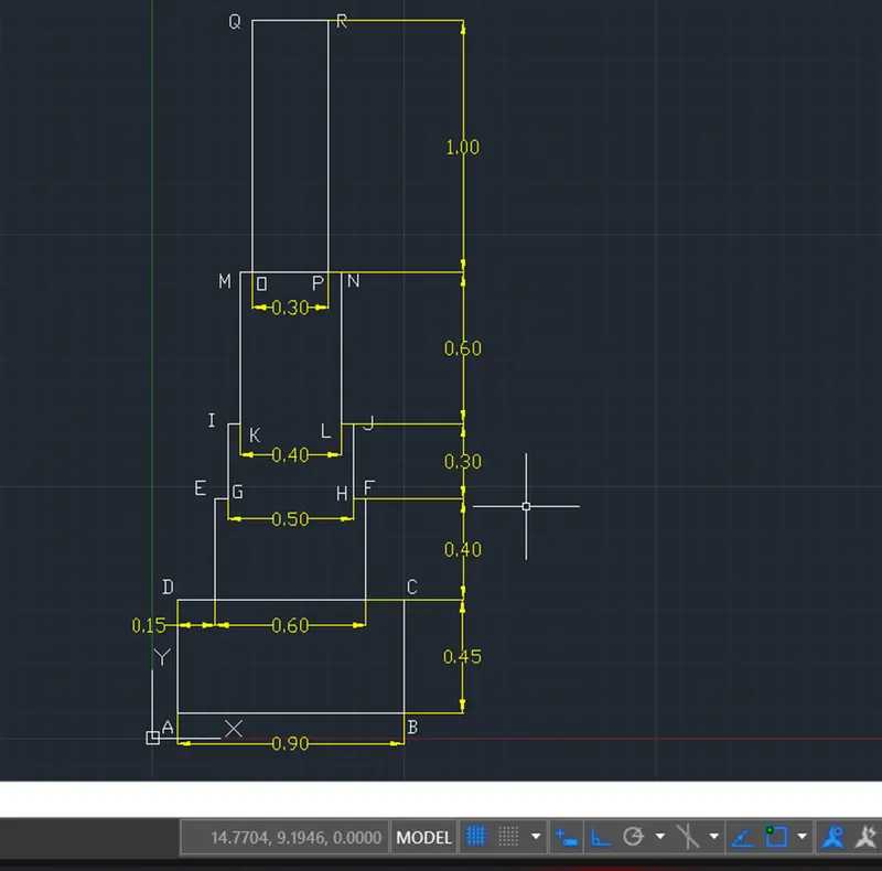
CONCLUSION: Thus, we have drawn the Cross Section of Load bearing wall showing foundation details as per the given sketch in C4 using various commands illustrated in attached screenshots and procedure.
FIGURE C5
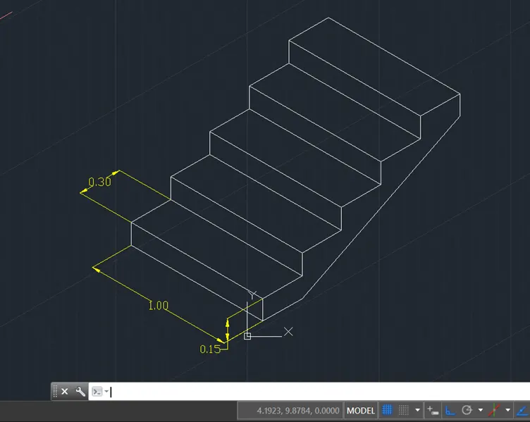
AIM: To draw the Isometric view of steps as shown in figure of attachment C5.
PROCEDURE:
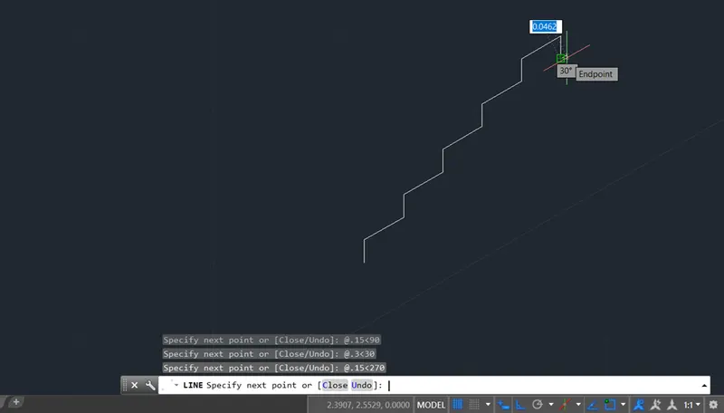
Select ISOPLANE Right for isometric view drawing or it can be drawn on normal orthoplane using Polar coordinates
Enter L (line) command and start point (1,1)
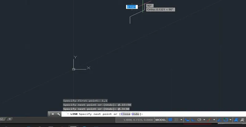
Second point upward for a distance of 0.15 in ISOplane or @0.15<90 for normal orthoplane
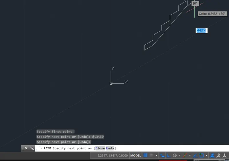
Continue line for horizontal line of 0.30 in ISOplane or @0.3<30 for normal orthoplane
Continue till edge line of 5 steps are formed.
For final step continue line downward for distance of 0.15 in ISOplane or @0.15<270 for normal orthoplane
From first start point draw a horizontal line of 0.3 in ISOplane or @0.3<30 for normal orthoplane
Connect the two extreme open end points to form the soffit line
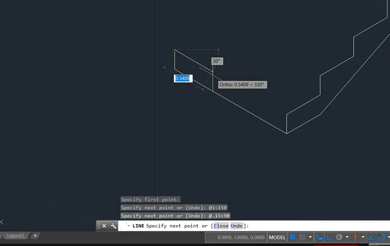
Change the Plane to ISOPLANE left or continue with normal orthoplane
Draw horizontal line of distance 1.00 towards left in ISOplane or @1.00<150 for normal orthoplane
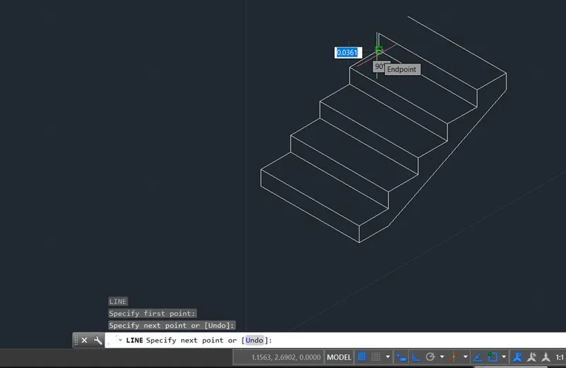
Continue drawing the 1.00 lines from all the corners towards left
Join the 0.15 lines vertically by connecting two points for risers similarly continue joining the 0.30 lines horizontally by connecting two adjacent points for treads
Scale up the drawing for larger view if required.
Adjust the dimension text, lines, scale etc using DIMSTY command.

CONCLUSION: Thus, we have drawn the Isometric view of steps as per the given sketch in C5 using various commands illustrated in attached screenshots and procedure.
FIGURE C6
AIM: To draw the Isometric view of gable wall as shown in figure of attachment C6.
PROCEDURE:
Switch on ISOPLANE mode and select the ISOPLANE right mode
Enter L(line) command and start point (1,1) and draw a horizontal line of 1.00 towards right (towards 30 degree)
Draw vertical line of 2.42 upwards in continuation then again, a horizontal line of 1.00. Continue drawing vertical line of 2.42 downward then again, a horizontal line of 1.00 and finally vertical line of 3.00 upward.
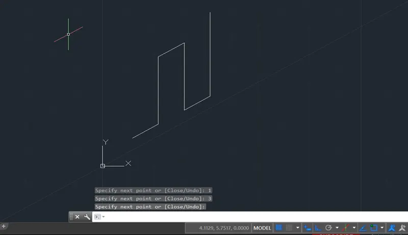
From the start point draw a 3.00 vertical line upward
From start point draw a horizontal reference line of 1.50 and a vertical line on 3.25 in continuation for reference of top of gable wall.
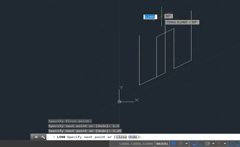
Connect the two 3.00 vertical line top points with the 3.25 reference vertical line top. Thus the gable wall top is formed.
Delete the 1.50 horizontal and 3.25 vertical reference lines.
Change the ISOPLANE mode to ISOPLANE left
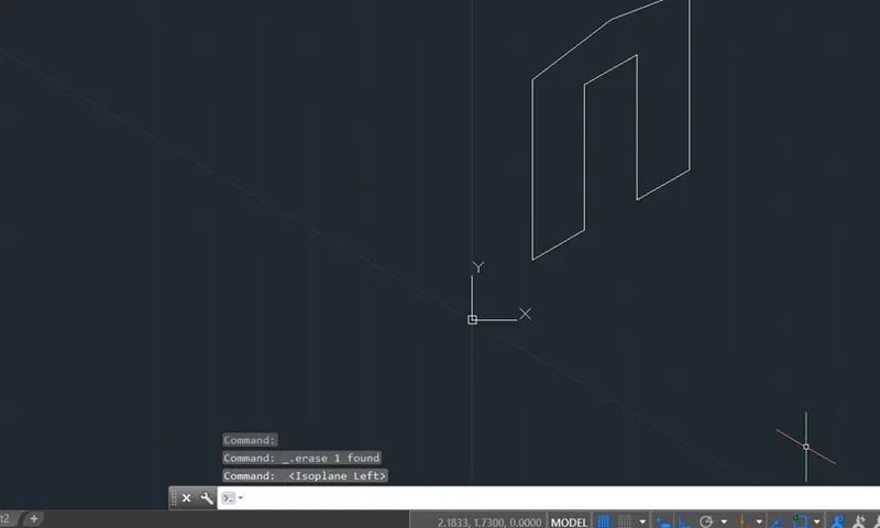
From start point draw a horizontal line of 0.30 towards left (towards 150degree) and continue drawing vertical line of 3.00 upward.
Draw horizontal lines of 0.30 on gable wall top point, side points and the bottom of door opening point.
Connect the top left side, centre and right sides of gable wall top horizontal lines.
Draw a vertical line from the door bottom horizontal to meet the top of door opening.
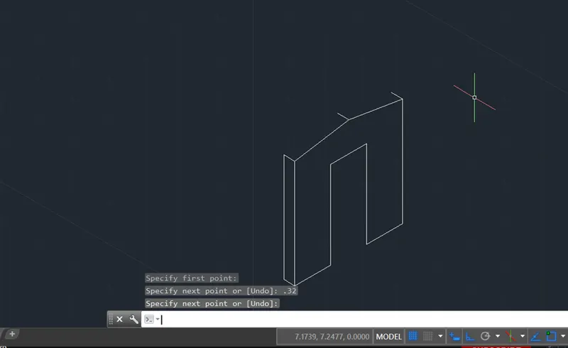
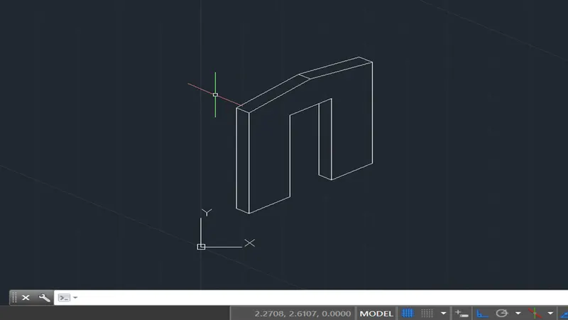
The required gable wall drawing is ready.
Scale up the drawing by scale factor 10 for larger view if required.
Adjust the dimension line, arrow, text etc by using DIMSTY command.
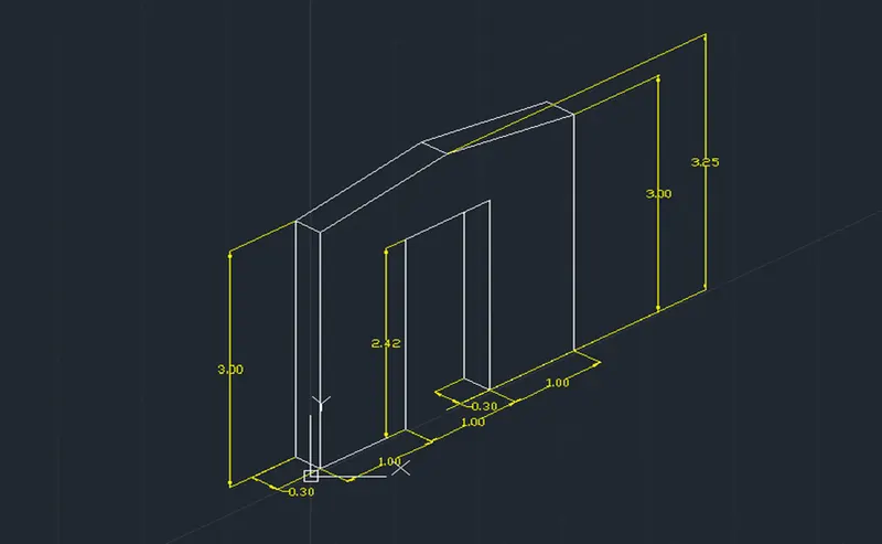
CONCLUSION: Thus, we have drawn the Isometric view of gable wall as per the given sketch in C6 using various commands illustrated in attached screenshots and procedure.