Project 2_Creating a 3D rendered model for a Residential Building in AutoCad
AIM
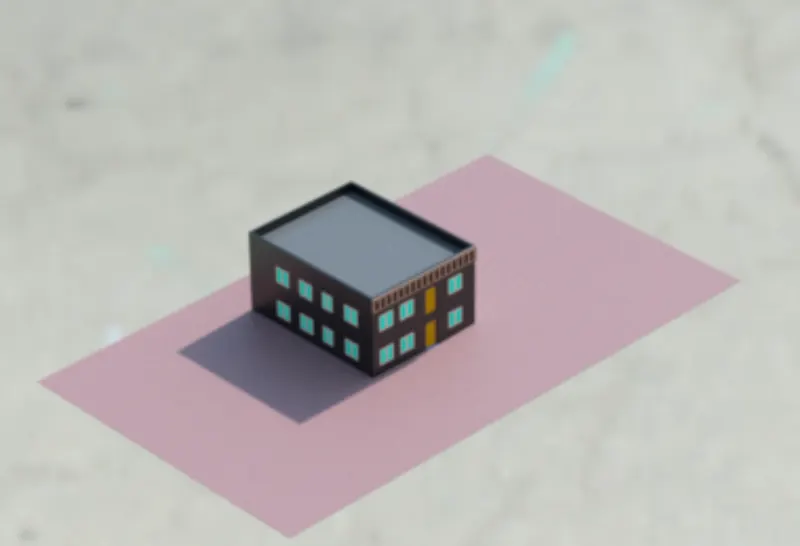
To Create a 3 dimensional model of the residential building with a rendered view.
INTRODUCTION
- 3D (3 dimensional) modelling basically refers to the process of developing the mathematical representation of any surface of an object in three dimensions using specilalized software
- This representation is called 3D model and a person working with 3D models is called a 3D artist
- The process of displaying the 3D model as a two - dimensional image is called 3D rendering
- 3D modelling is used in various fields such as films, animation and gaming ,interior designing and architecture
COMMANDS USED
- Unit command
- Limit command
- Line command
- Offset command
- Trim command
- Rectangle command
- Dimlinear command
- Mtext command
- Dimstyle command
- Move command
- Copy command
- Extrude command
- 3dorbit command
- Region command
- Boundary command
- ucs command
- subtract command
- union command
- 3Dface command
- distance command
- boundary command
- 3Drotate command
- plan command
- solid edit command
- explode command
- erase command
PROCEDURE
STEP 1
- Open a new file
- In the command line type units , select the units and also set the precision
- In the command line type 'LIMITS' and specify the limits at lower left corner and upper right corner as
- Then zoom all
STEP 2
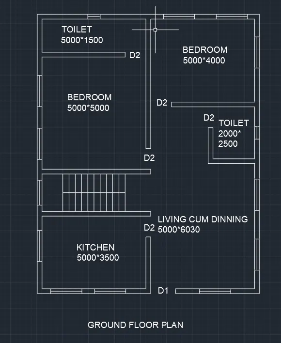
GROUNG FLOOR PLAN
- First to draw the ground floor plan
- Using line ,offset ,trim and extend command draw two bedrooms of size 5000*5000 and 5000*4000
- Toilets of size 5000*1500 and 2000*2500
- Then drawing stair room with landing as 1000
- Tread is 300 and rise is 150
- kitchen of size 5000*3500 and living cum dinning area is drawn
- Wall thickness is given as 230mm
- openings are provided at the place of door
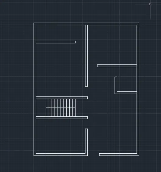
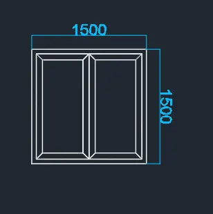
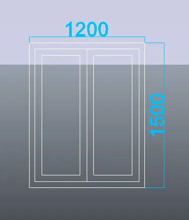
- window openings are made size of window is given as W1- 1500*1500 ,W2- 1200*1200, V1 -600*900
- Sizes of doors are 1000*2100 and 1200*2100
- Using mtext command texts are written
STEP 3
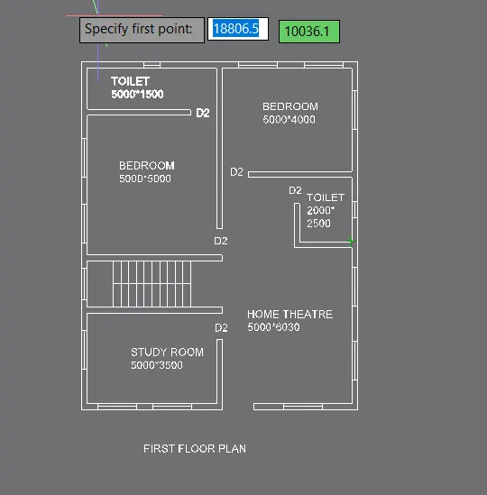
FIRST FLOOR PLAN
- copy the ground floor plan
- make necessary changes required for the first floor plan
STEP 4
3D plan
- From the settings icon that is the icon of the workspace
- Select 3d modelling
- then create layers for making 3d model
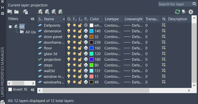
- Using the boundary command create region
- and then by extrude icon extrude it to a height of 3000 for making wall
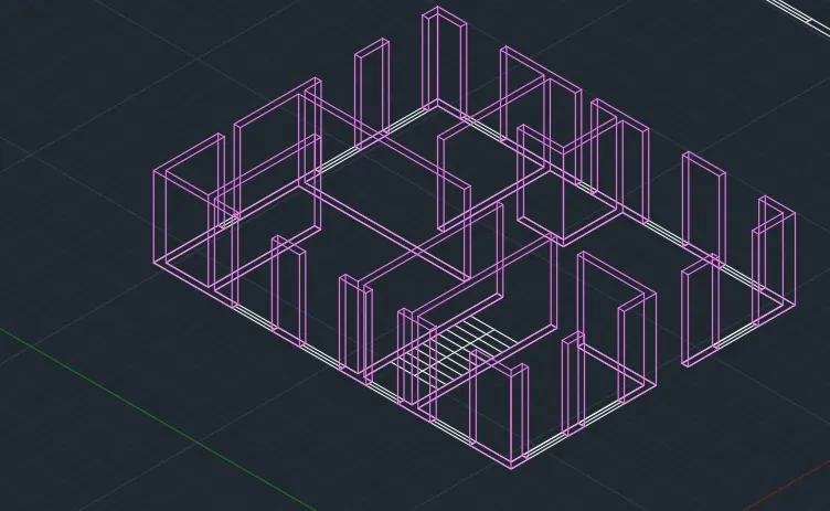
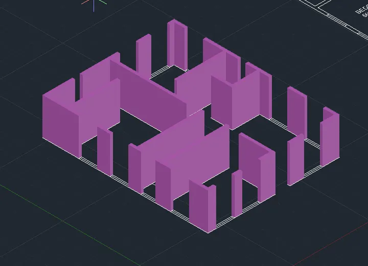
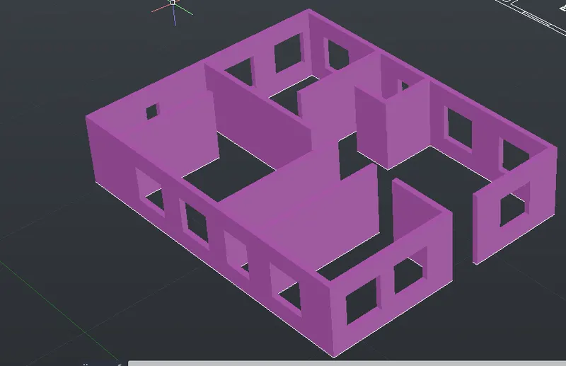
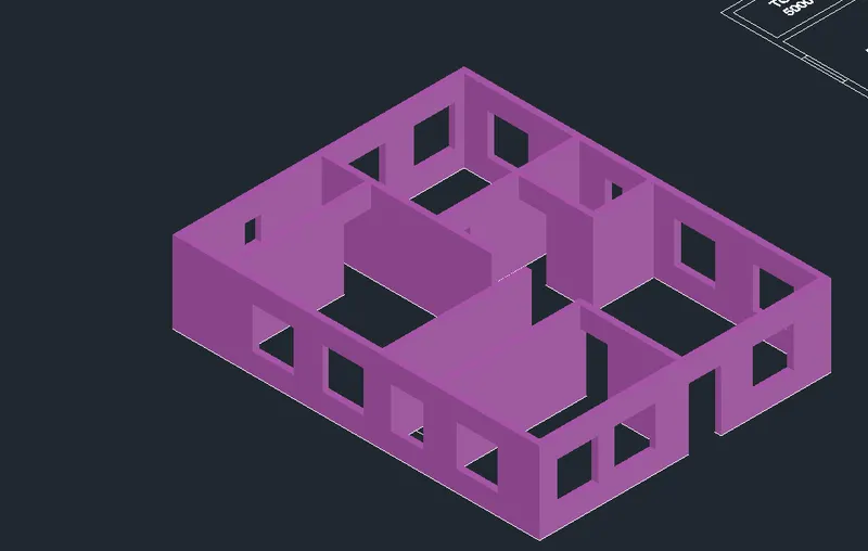
- inorder to draw the window draw rectangle at the space of windows, doors and change them into boundaries
- then extude it using the extude command , leave the space for the window
STEP 5
CREATING 3D DOORS AND WINDOWS AND PLACING THAT IN PLAN
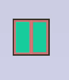
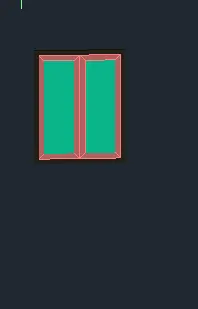
- Then we draw window of size 1500*1500and 1200*1500 , ventilator size -600*900 and door using rectangular command
- by using offset command offset it
- using extrude command will extrude it
- using layer command we will layer it
- change the layer for all the boxes respectively
- we can do that using boundary command and subtract command
- Then all layers are extruded
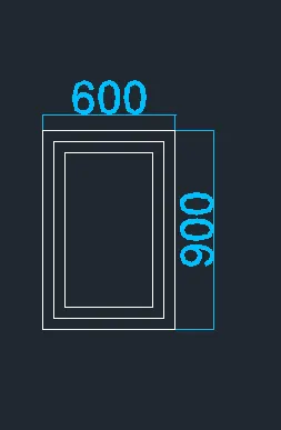
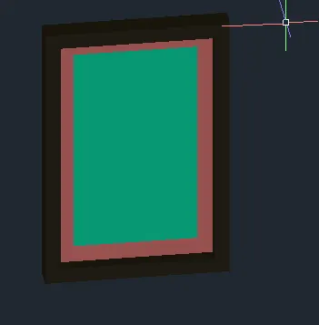
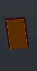
- place the created doors and windows in appropriate places and plinth of 600 is created at the bottom
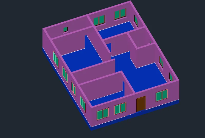
- copy the extruded walls for first floor
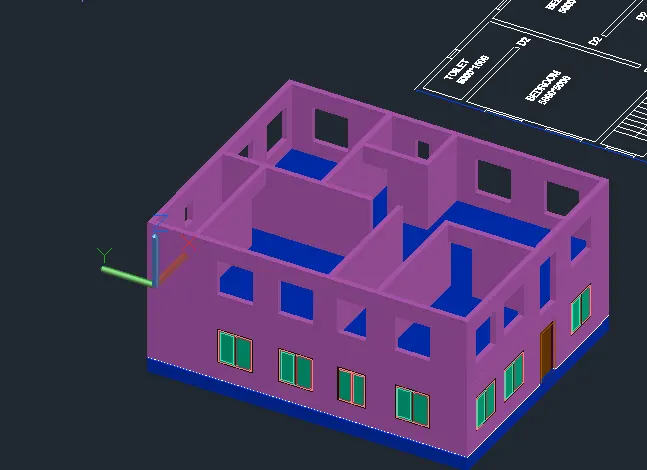
- using move and copy command windows are placed at their desired location
- using polyline at the terrace and create the parapet wall at the top of the building
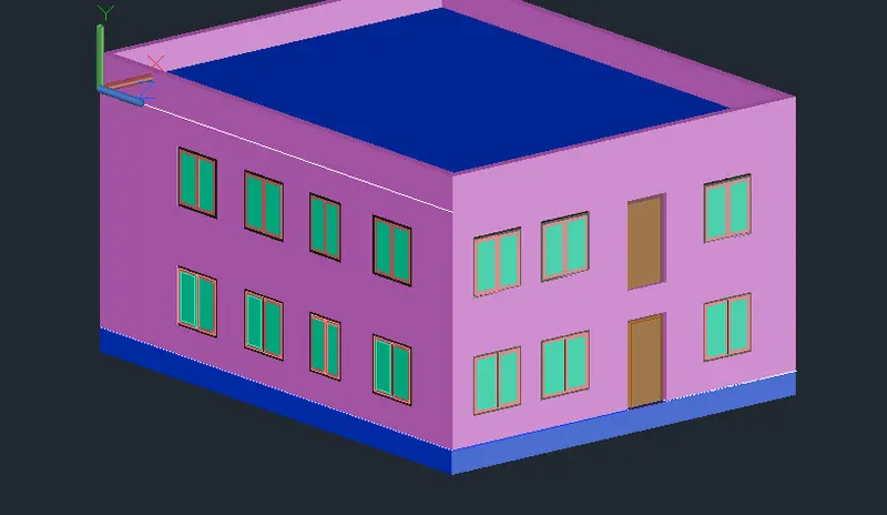
- using layer properties colour of the wall is changed
- using rectangle , boundary and extrude commands steps are created and placed in proper positions
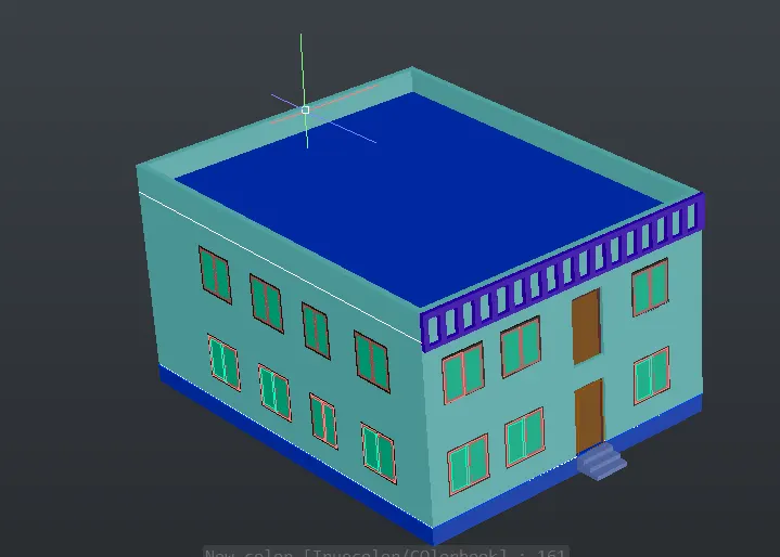
STEP 6
CAMERA VIEW
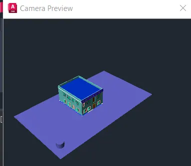
- Using camera command camera is placed
- we need provide location for the camera ,target location,name, lens,height
- then enter we can see the camera view
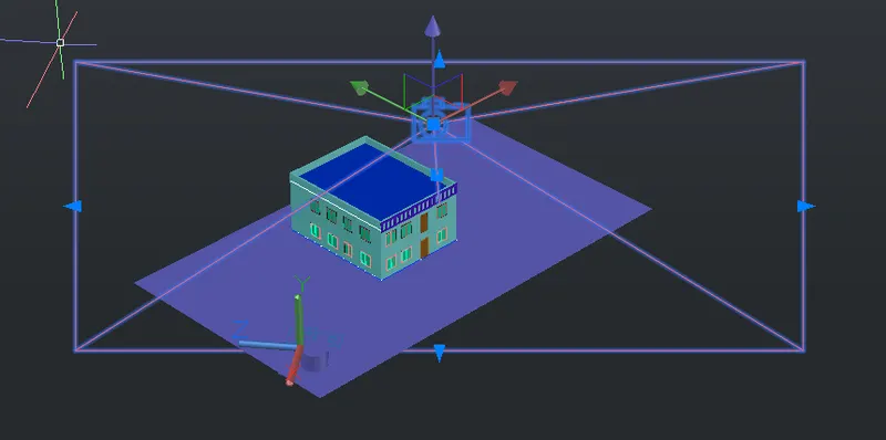
STEP 7
RENDERING
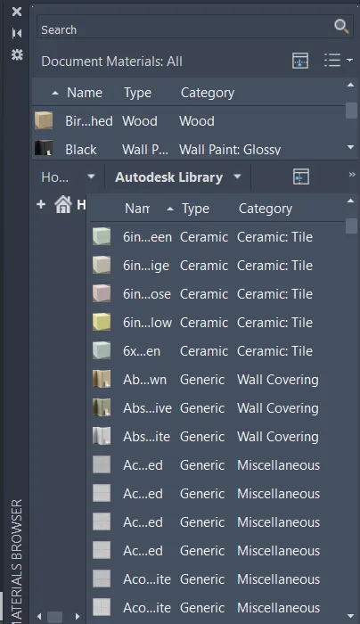
- rendering is done by material using material browser
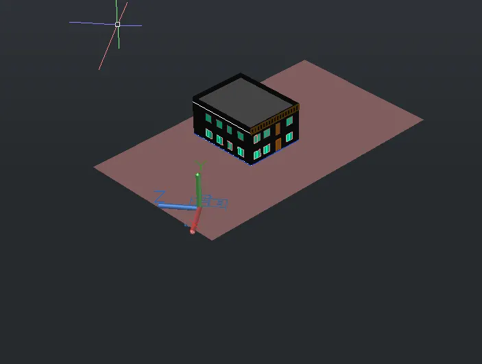
- Using rr command we can render
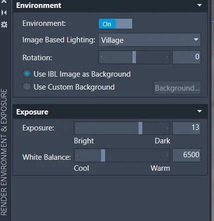
- we can select the size , time , enivironmental exposure etc
RESULT
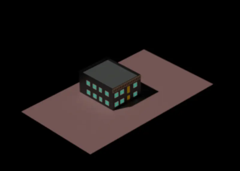
3D rendered model of a residential building is created
--------------------------------------------------------------------------------------------------------------------------------------------