Project 2_Creating a 3D rendered model for a Residential Building in AutoCad
Aim:
To create a 3D model of the residential building with rendered view.
Introduction:
The 3D model of the residential building is start from creating plan and change into 3D workspace create 3D model. Assigning the materials to the model and render the model. Most commonly used commands are line, trim, construction line, fillet for creating the plans and boundary, region, extrude, UCS, 3D rotate, copy, move for creation 3D model.
Gendral dimensions,
- Outer wall - 230mm
- Iner wall - 115mm
- Door 1 - 914mmX2133mm
- Door 2 - 762mmX2133mm
- Window - 1524mmX1219mm
- Ventilator - 600mmX600mm
- Steps,
Riser - 150mm
Thread - 300mm
Ground floor plan details,
- Living - 2923mmX3962mm
- Bedroom - 4572mmX3048mm
- Toilet - 2438mmX1524mm
- Kitchen - 3962mmX3657mm
- Dining - 3657mmX3657mm
- Parking - 2932mmX3657mm
First floor plan details,
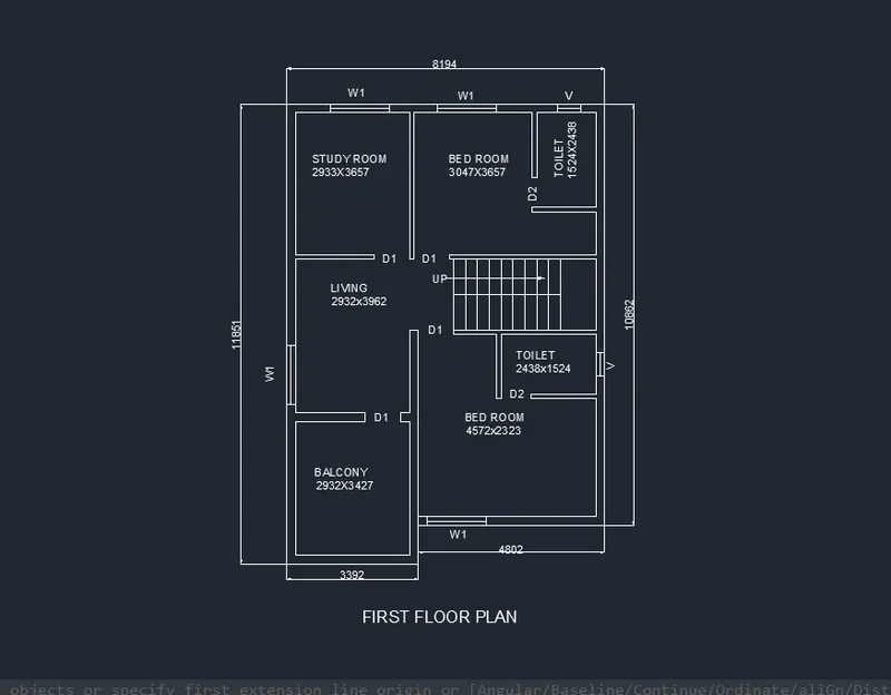
- Living - 2923mmX3962mm
- Bedroom 1 - 4572mmX3048mm
- Bedroom 2 - 3047mmX3657mm
- Toilet 1 - 2438mmX1524mm
- Toilet 2 - 1524mmX2438mm
- Study room - 2933mmX3657mm
- Balcony - 2932mmX3427mm
Procedure:
- Open Autocad software in metric units.
- Set the units as decimal.
- Precision as 0
- Set limmax as 10000,10000
1. plan:
Ground floor plan:
- Create horizantol and vertical construction line.
- Offset the lines at a distance of 230mm.
- Fillet it with radius of 0mm to make the corner of wall.
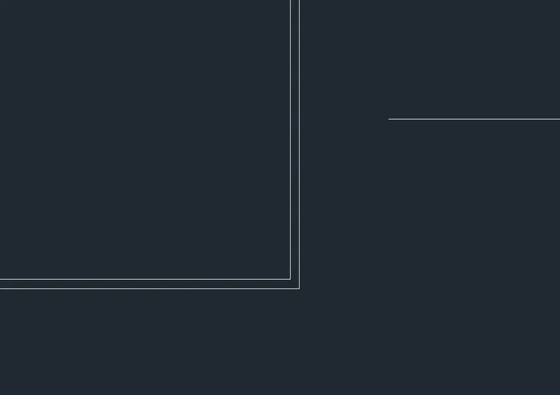
- Offset the line at 4572mm and 230mm.
- Offset the horizontal line at 3048mm, 115mm, 1524mm and 115mm respectively.
- Use trim command trim the unwanted lines.
- Offset the horizontal line at 1828mm and 115mm.
- Create stair.
- Offsset the vertical line at 914mm to create landing.
- Offset the offseted line at 300mm of 9 numbers of offset.
- Use trim command remove the unwanted lines.
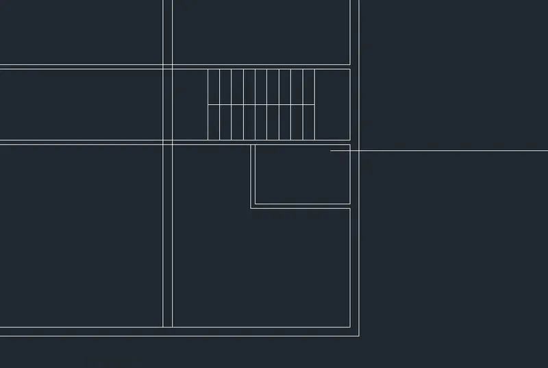
- Offset the horizontal line at 3657mm and 230mm respectively.
- Offset the vertical line at 3657mm, 115mm, 3962mm and 230 mm.
- Extend the left side created line throughout the start line of the plan.
- Use trim tool remove the unwanted lines.
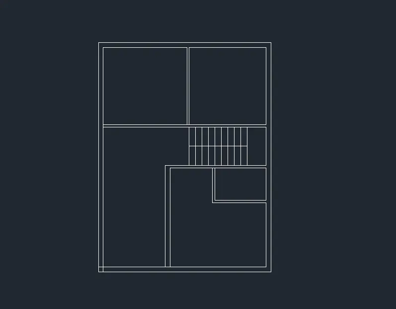
- Offset the horizontal line at 3962mm and 230mm.
- Trim the unwanted lines.
- Offset the last created line at 3657mm.
- Extend the left side wall line to it.
- Errase the last offseted line.
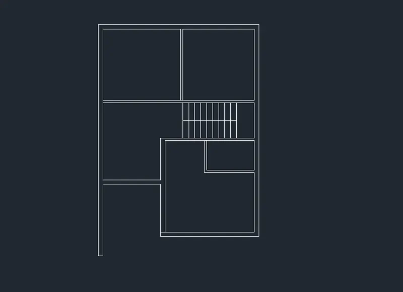
- Use offset, trim, line tool to create the door and window opening.
- Use 'ST' command, set the text style.
- Text style as 'Arial'
- Text height 150mm
- Use 'MT' command, create text to the plan.
- Use 'Dimlin' command to create dimensions in the plan.
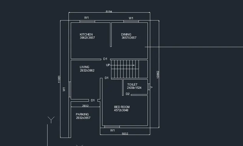
First floor plan:
- Copy the ground floor plan and place it any where in the workspace.
- Use erase command, remove the changed wall lines.
- Offset the line of the kitchen at a distance of 2933mm and 115mm.
- Create a wall in the balcony front side of thickness 230mm.
- Create doors and windows in the plan.
Terrace floor plan:
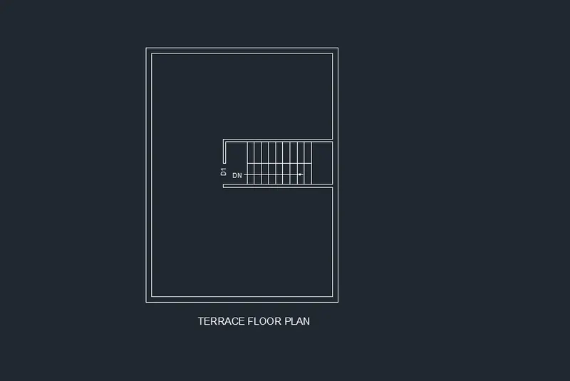
- Copy the first floor plan and place it any where.
- Use trim and offset command to create the terrace floor plan.
- Create head room walls of thickness 115mm.
- Parapet wall thickness 230mm.
2. 3D modeling:
- Switch the workspace drafting and annotation to 3D modelling workspace.
- Set the view as South-West isometric.
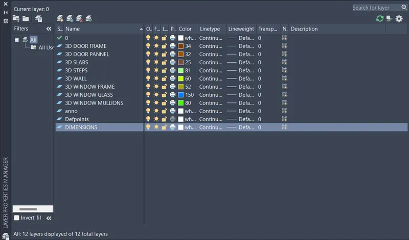
- Create the following layers,
3D wall
3D door frame
3D door pannel
3D window frame
3D window mullion
3D window glass
3D steps
3D slabs
Door, window and ventilator:
- Set the view as plan.
- Set door frame layers as curent layer.
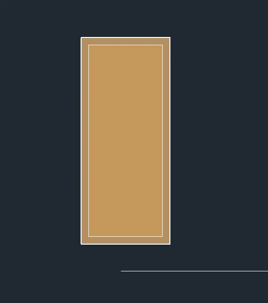
- Create rectangle of size 914mmX2133mm.
- Offset it at a distance of 75mm.
- Use 'Boundary' command create region of the door.
- 'Subtract' the door frame from pannel.
- Create boundary to the pannel.
- Set the view as South-West isometric.
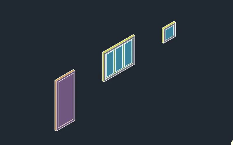
- Use '3D rotate' tool, rotate the door face at 90 deg with respect to X-axis.
- 'Extrude' the door frame at a distance of 75mm.
- 'Extrude' the door pannel at a distance of 30mm.
- 'Move' the pannel at a distance of 20mm inner side of the frame.
- Follow the same procedure to create windows and ventilator.
Steps:
- Set the view as plan.
- Set steps layer as current layer.
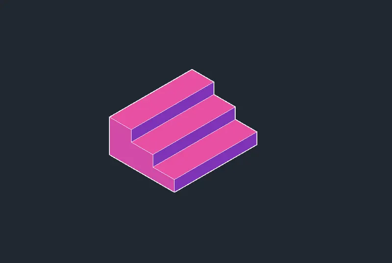
- Create rectangle of size 1144mmX300mm.
- Copy it and place it to create another 2 steps.
- Change the view to South-West isometric.
- Extrude the first rectangle at a height of 150mm.
- Extrude the second and third rectangle at a height of 300mm and 450mm respectively.
- 'Union' the created steps to make it as a single object.
1. Ground floor:
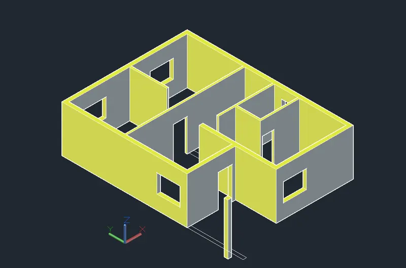
- Create wall.
- Trun off the annotation and dimension layers in the plan.
- Set 3D wall layers as current layer.
- Use 'Boundary' command, create regions of walls in ground floor.
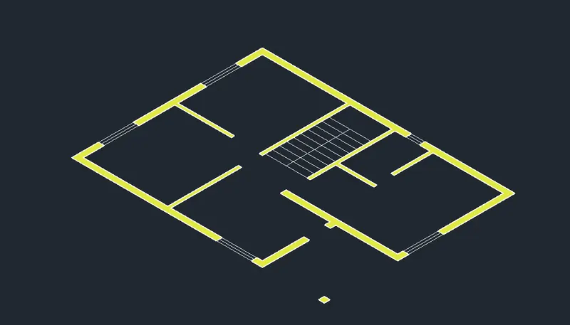
- Extrude the region at a height of 3048mm.
- Create doors and windows openings.
- Create rectangle at the bottom and top of the walls in doors and windows location.
- Extrude the bottom rectangle of windows at 914mm.
- Extrude the top rectangles at a depth of 914mm.
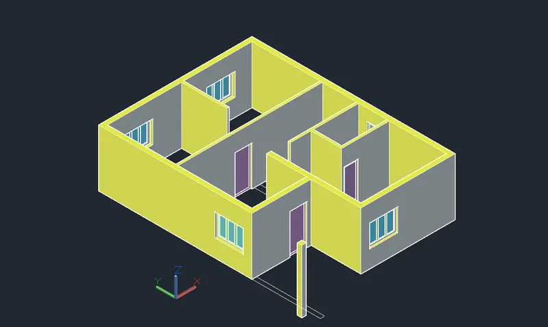
- Use 'copy' tool copy the doors and windows.
- Place it to the opening of the doors and windows.
- Move it at a distance of 100mm inner side.
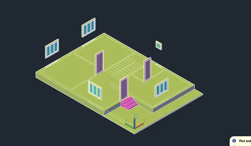
- Create plinth area.
- Change the view to plan.
- Create polyline in the place of plinth area.
- Trun off the wall layer.
- Use 'Boundary' command, create region of it.
- 'Extrude' the region at a depth of 550mm.
- Follow the same procedure to create floor in the car parking area.
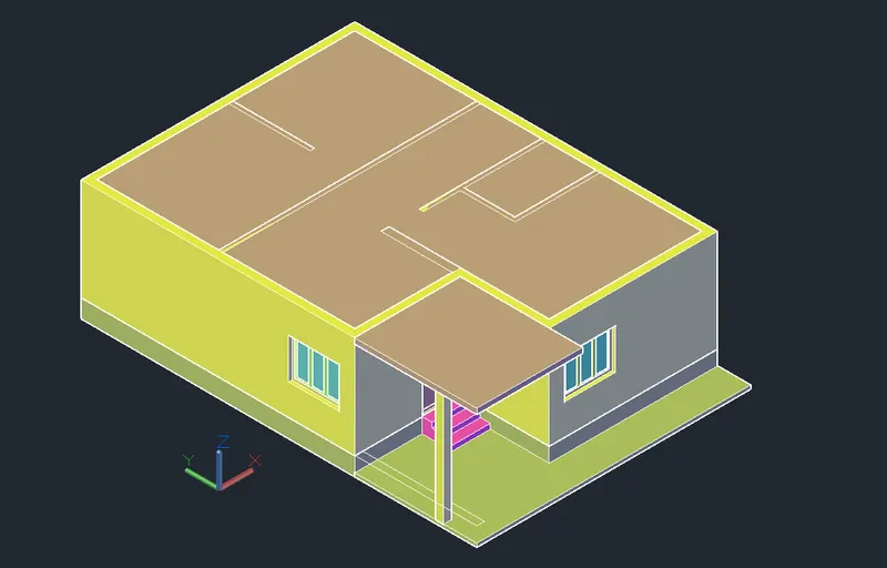
- Create slab.
- Trun on the 3D wall layer.
- Change the UCS at the top of the wall.
- Create a polyline at the top of teh wall.
- Use 'Boundary' command create region of the polyline.
- Extrude it at a depth of 150mm.
2. First floor:
- Create first floor.
- Use 'Boundary' command create region of walls in the first floor plan.
- Follow the procedure followed in the ground floor creation.
- Extrude walls at a height of 3048mm.
- Extrude parapet wall at a height of 914mm.
- Create doors and windows openings.
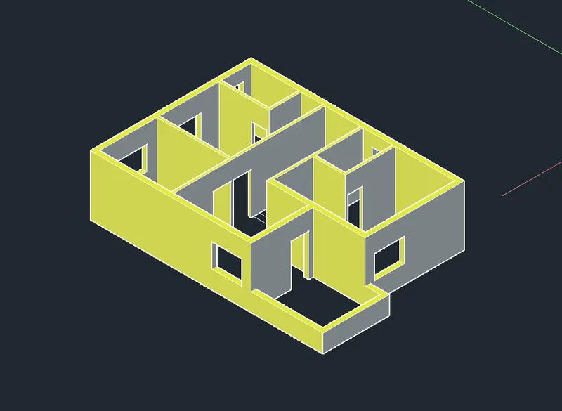
- Copy doors and windows and place it in the openings created.
- Copy the extruded first floor and place it above the ground floor.
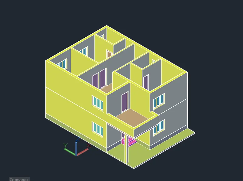
- Create first floor slab.
- Change the UCS to the top of the wall in first floor.
- Set slab layer as current layer.
- Create rectangle at the internal points of the wall.
- Extrude the rectangle at a height of 150mm.
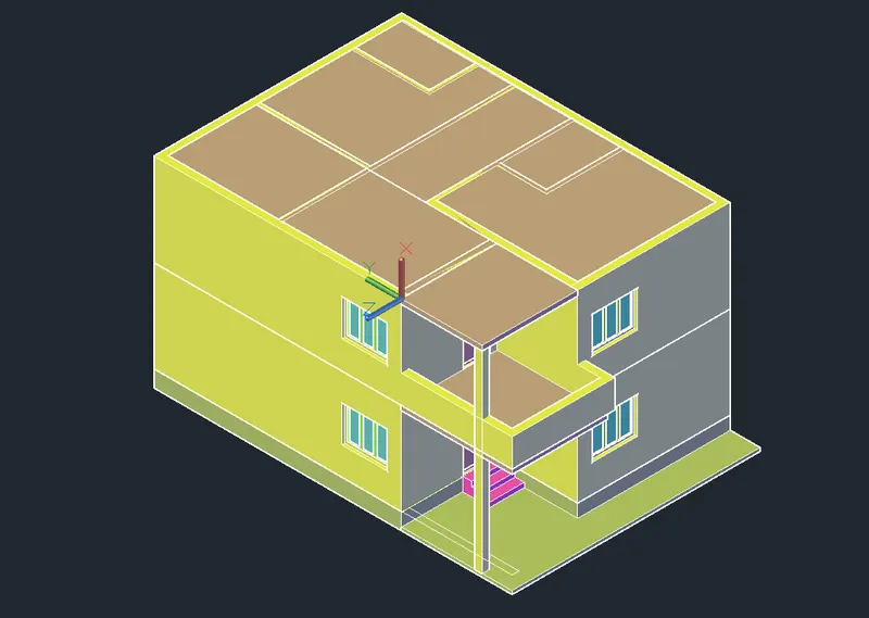
- Create terrace floor.
- Use 'boundary' command, create region of the wall.
- Extrude the head room wall at a height of 2133mm.
- Extrude the parapet wall at a height of 914mm.
- Create slab at the top of the headroom.
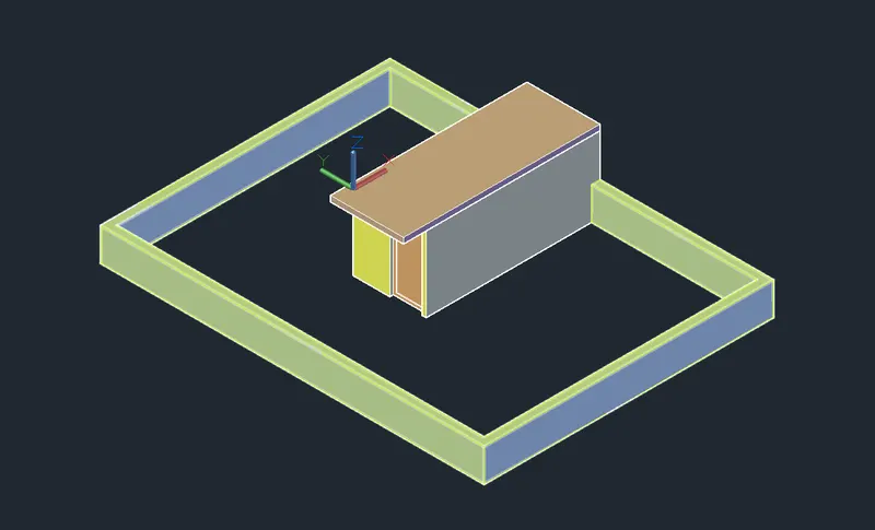
- Copy the created terrace floor.
- Place it above the first floor.
- Use 'Union' tool, Union all the walls.
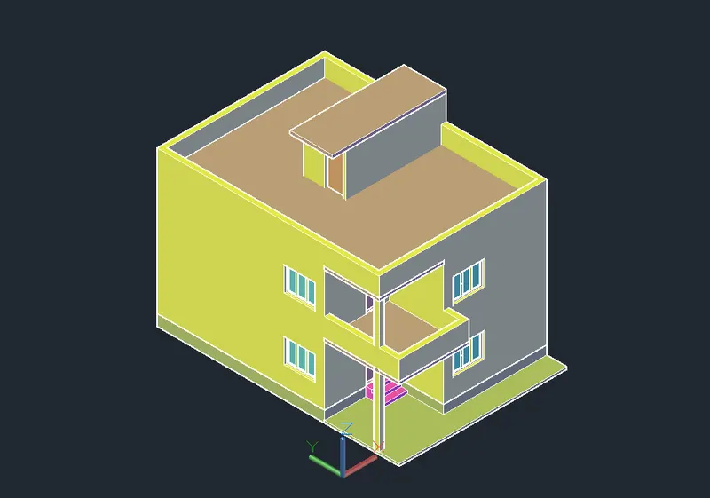
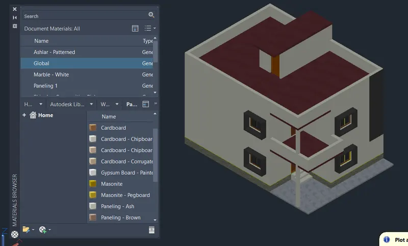
- Assign materials to the created model.
- Open 'material library' under the visualize tab.
- Select the materials like wall paint, wood, glass.
- Select the object in the model.
- Click assign to selected object.
- Use 'Setuv' command, map the material to fit the object in the model.
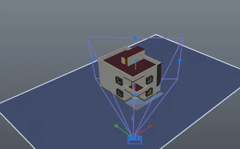
- Set camera to the object to create the views.
- Create circle at the ground level.
- Extrude it at a height of 1828mm.
- Select the 'Create camera' option under the visualize tab.
- Place the camera above the cylinder.
- Set the target and other parameters.
- Create 3 different views form the camera.
- Remove the cylinder.
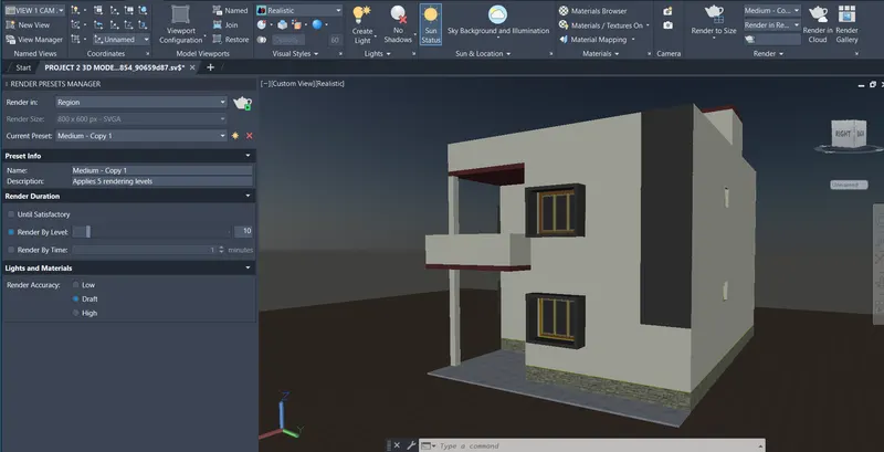
- Render the created 3D model.
- Select the view 'view 1'
- Set the distant light by creating the cylinder.
- Set the target as the building.
- Trun on Sky and illumination background.
- Trun on sun light.
- Use 'RR' command open the render presets manager.
- Click the render icon to start rendering.
- Use 'RW' command open the render window.
- Save the rendered image as .jpeg file.
Result:
A 3D model of the residential building with a rendered view is created.
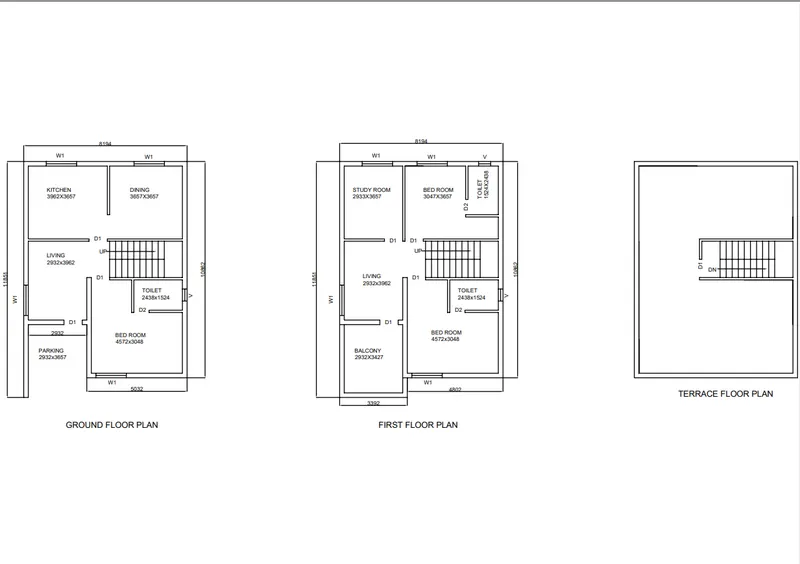
Floor plans.
3D model of the building.
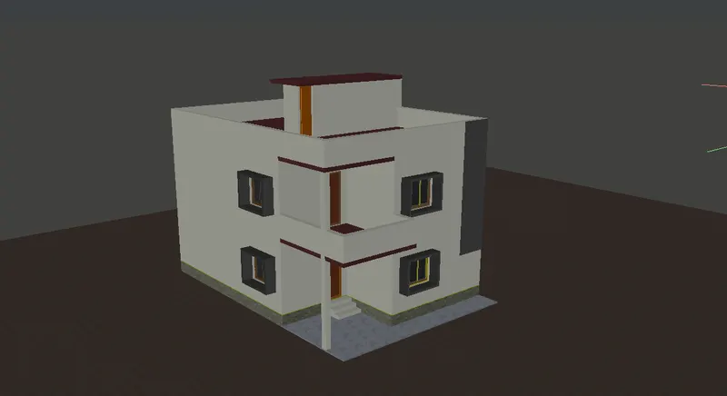
3D model materials assigned and ready to render.
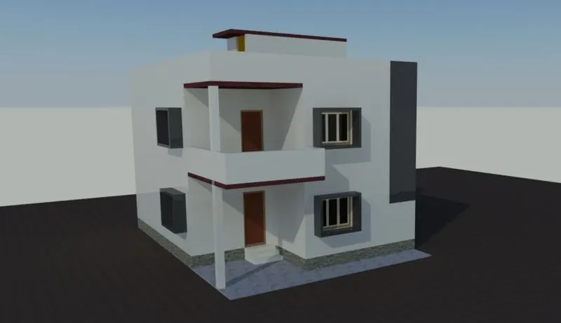
Rendered view 1.
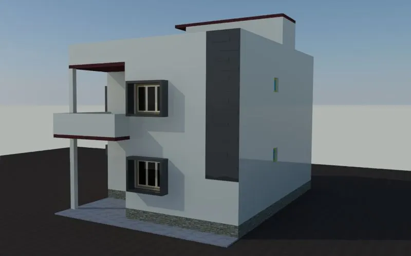
Rendered view 2.
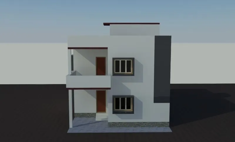
Rendered view 3.