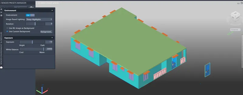
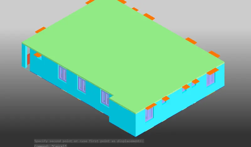
Project 2_Creating a 3D rendered model for a Residential Building in AutoCad
Aim: -
- To Create a 3 dimensional model of the residential building with a rendered view.
Procedure: -
- Give the Command of XL and Press Enter
- Select the V From the Command Bar and Specify the Corner of Work Space
- Press Enter
- Give the Command of XL and Press Enter
- Select the H From the Command Bar and Specify the Bottom of the Work Space
- Press Enter
- Select the Horizontal Line and Give the Command of Offset and Give the Offset Distnace as 250 and Press Enter
- Select the Previously Offsetted Line and Give the Command of Offset and Give the Offset Distnace as 3100 and Press Enter
- Select the Previously Offsetted Line and Give the Command of Offset and Give the Offset Distnace as 125and Press Enter
- Select the Previously Offsetted Line and Give the Command of Offset and Give the Offset Distnace as 4475 and Press Enter
- Select the Previously Offsetted Line and Give the Command of Offset and Give the Offset Distnace as 125 and Press Enter
- Select the Previously Offsetted Line and Give the Command of Offset and Give the Offset Distnace as 125and Press Enter
- Select the Previously Offsetted Line and Give the Command of Offset and Give the Offset Distnace as 3000 and Press Enter
- Select the Previously Offsetted Line and Give the Command of Offset and Give the Offset Distnace as 250 and Press Enter
- Select the Vertcical Line and Give the Command of Offset and Give the Offset Distnace as 250 and Press Enter
- Select the Previously Offsetted Line and Give the Command of Offset and Give the Offset Distnace as 3100 and Press Enter
- Select the Previously Offsetted Line and Give the Command of Offset and Give the Offset Distnace as 125and Press Enter
- Select the Previously Offsetted Line and Give the Command of Offset and Give the Offset Distnace as 2550and Press Enter
- Select the Previously Offsetted Line and Give the Command of Offset and Give the Offset Distnace as 125and Press Enter
- Select the Previously Offsetted Line and Give the Command of Offset and Give the Offset Distnace as 1250 and Press Enter
- Select the Previously Offsetted Line and Give the Command of Offset and Give the Offset Distnace as 125 and Press Enter
- Select the Previously Offsetted Line and Give the Command of Offset and Give the Offset Distnace as 1250and Press Enter
- Select the Previously Offsetted Line and Give the Command of Offset and Give the Offset Distnace as 125and Press Enter
- Select the Previously Offsetted Line and Give the Command of Offset and Give the Offset Distnace as 3000 and Press Enter
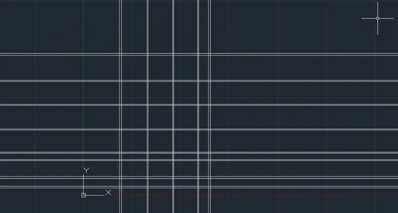
- Give the Command of Trim for Trim the Unwanted lines
- Give the Command of Fillet to Corner poitns Where iTs Required
- Give the Offset Suitable Places as Per Given Figure
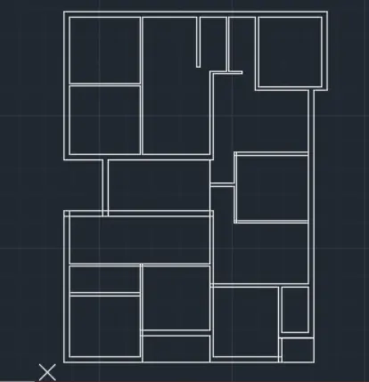
- Create a New layers From the Ribbon Tab as per Requiremernt
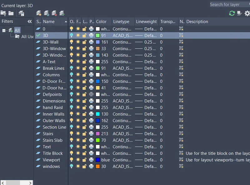
- Select a Layer From the Ribbon Tab Create New layers as a Outer Walls and Select the Colour Suitble For it.
- Create another layers as a Inner Walls and Select the Colour Suitble For it.
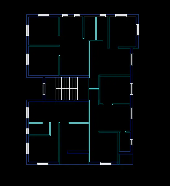
- Select the outer Walls and Set the Layer to Outer Walls Press enter
- Select the Inner Walls and Set the Layer to Inner Walls Press enter
- Trim the Lines For Doors Where its Suitable assume required size to Its and Press Esc.,
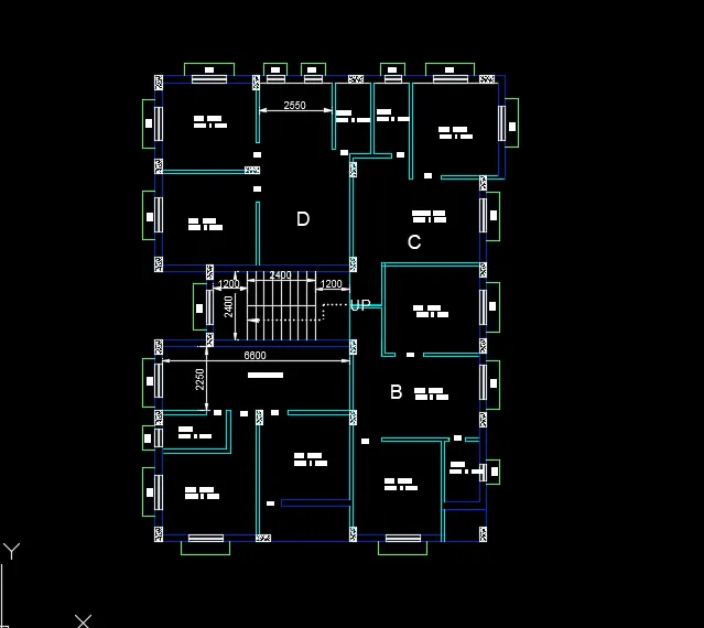
- Draw a Rectangle as a Suitable size of Column Size and Hatch it as a Concrete and Press enter
- Copy the Object and Place its Very Its Suitable as Per Given Figure
- Draw a Rectangle as a Suitable size of Window Press enter
- Copy the Object and Place its Very Its Suitable as Per Given Figure
- Create another layers For Linel Line and Select the Colour & line Type as Dot Dot and Press Enter
- Set Its to a Curent Layer and Draw a Line As per Given Figure
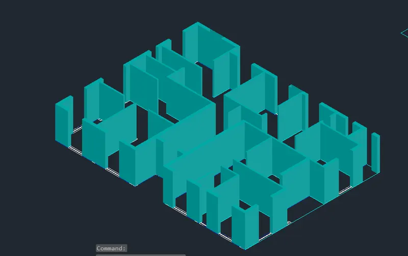
- Change the View to 3D By Clicking on Hme Button of View Cube and chance to the View to Right View
- Set UCS as Right
- Start Line Command and Draw a vertical line of Length 158.3 mm
- Draw a Horizontal Line of Length 300 mm
- Repeat the same Process for 8 times to Draw 8 Steps
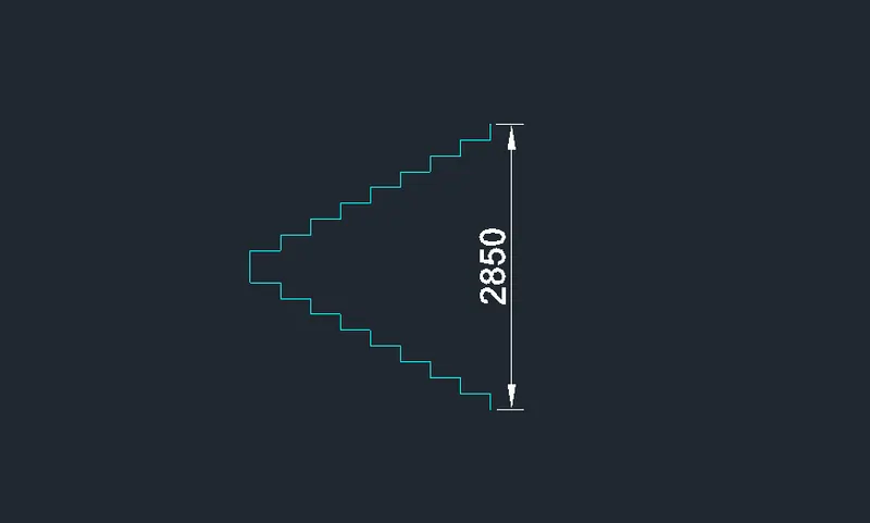
- After reaching 8 Steps draw a landing of length 1200 mm
- Draw line of 115 mm at the Bottom Step
- Draw Line 115 mm at the top right edge of Landing
- Draw a Line of 115 mm Backwards
- Draw a slab Joining the Lines
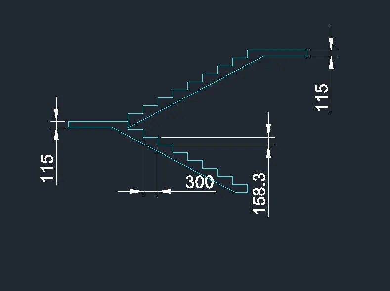
- Change the View to 3d by Clicking on Home Button of View Cube set UCS as World
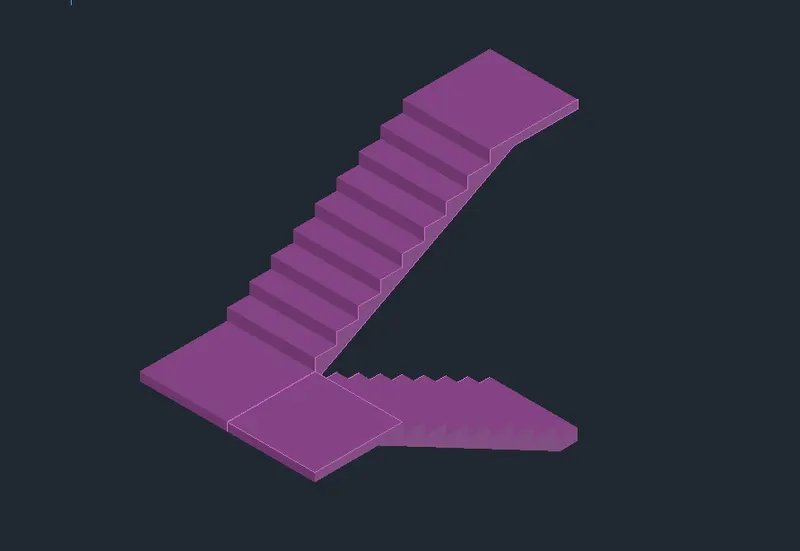
- Create a region from the Side View the Stairs
- Extrude the side view to distance of 1200 mm as shown in fig
- Change the Layer to Stair hand rails
- Draw Circle of diameter 25mm with 50 mm offset From the Top rights Edges of the First Thread of Staircase
- Chance the Circle in to region
- Extrude the Region to a Height of 800mm
- Change the Current layer to Stair -hand rails Stand
- Draw a Poly Line alonf vithe Vertical rails Create a Region of hand rail By Using Sweep Option
- Using the Copy Command Copy all the Hand Rails Components on all Stairs
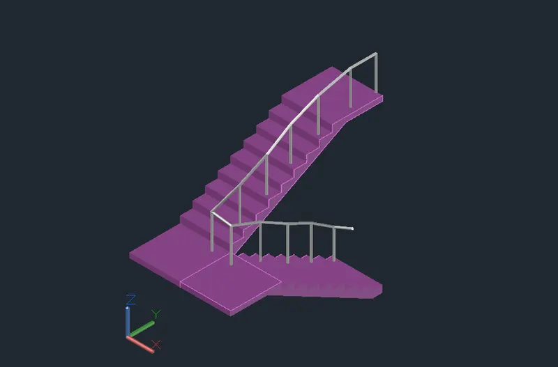
Given the Comamnd of Copy and Specify the Base Point and Move and Specify the Second Ponit Press enter
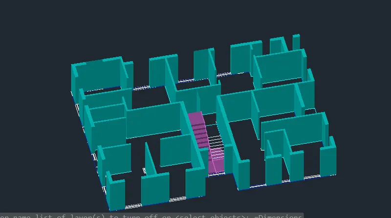
- The Next Step is to Create Opening for Windows in the Wall of the Building
- Create rectangle region at the location of the Window
- Extrude the Rectangle to thickness wall
- Subtract the Rectangle region to Create the Openings as Suitable
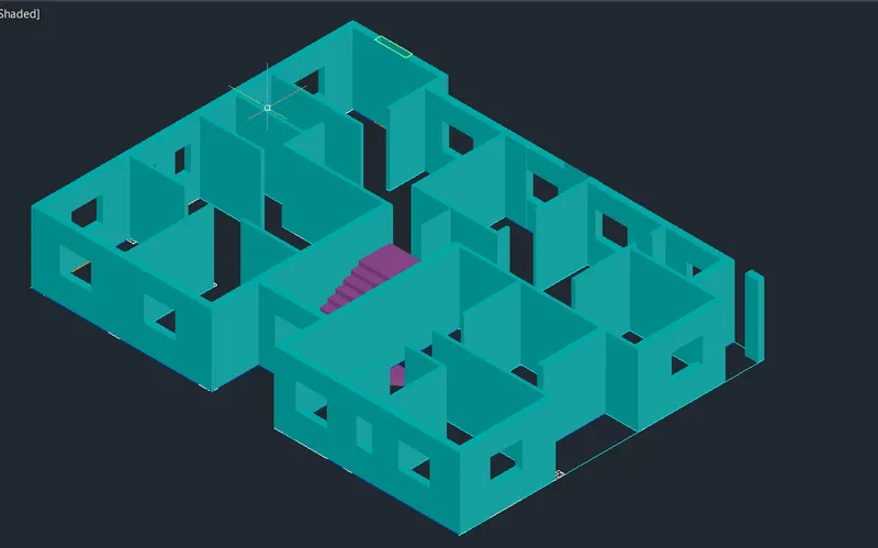
- Change the Current layer to 3D Window Frame
- Type UCS and Click on Face and Select the Face having 1000 mm Wide window
- Draw Rectangle of Dimensions 1200 mm
- Offset the Rectangle to inside the Distance of 50 mm
- Offset the Rectangle to inside the Distance of 30mm
- Start the Boundary Command and Click on Pick Points
- Click Inside the Window frame area and Press enter
- Give the Subtract Command
- Select Bigger region and Then Select the Smaller Region to Subtract them
- Follow the same Procedure for all the three boxes as Shown in figure
- Change the Current layer to 3d Window Mullion
- Start the Boundary Command and Click on Pick Points
- Click Inside the Window frame area and Press enter
- Give the Subtract Command
- Select Bigger region and Then Select the Smaller Region to Subtract them
- Change the Current layer to 3d Window Mullion
- Start the Boundary Command and Click on Pick Points
- Click Inside the Window Glss area and Press enter
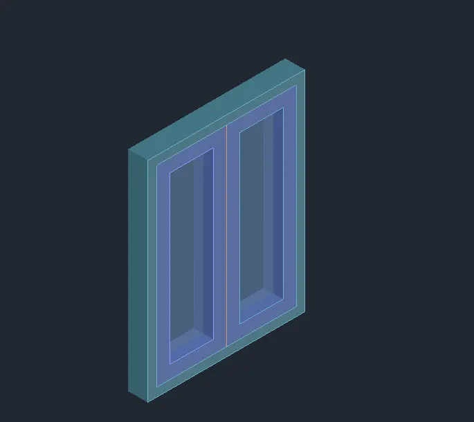
- Select the Window Frame and Give the Command of 3Drotate rotate the Window through Z Axis required angle
- Give the Copy Command Place its as its Requirement
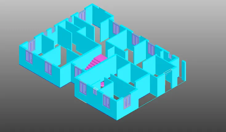
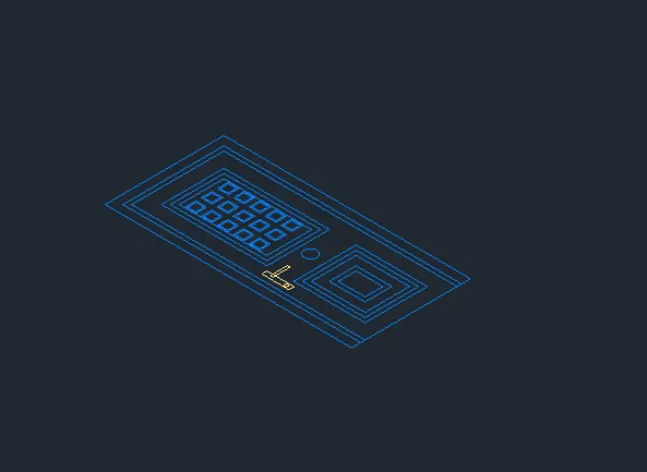
- There are three door types of Different Dimensions as per the introductions
- Draw Door as Per Requirement
- Create a 3D View of Door By Extruding the Frame and Mulion Components as Per Requirement
- The Model is Created into a Block
- Convert the all types of doors in to 3d Model Block
- Go to Block editor and add rotate parameters and Rotate action to all the Door Types
- Select the Door Frame and Give the Command of 3Drotate rotate the Window through Z Axis required angle
- Give the Copy Command Place its as its Requirement
- Change the Current Layer to SunShade
- Change Ucs to Right or Left side
- Draw horizontal line of Length 500 mm
- Draw a Vertical Line of Length 50mm to the top from last Point
- Draw a Horizontal Reverse line of Length 500mm from last point
- Press enter twice
- Draw a Vertical Line from the Start Point of Length 100mm Draw a Vertical Line on Length 50mm to the top from last Point
- Edit horizontally line by grips and draw the one end and place it on the Point at 100mm above the bottom Point as Shown in fig
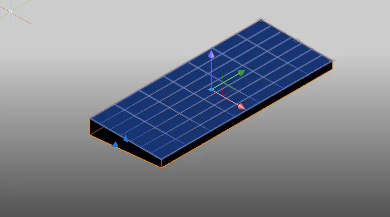
- Create region of the Closed area as Shown in fig.,3
- Extrude the Region Depending Required Length
- Select the Sunshade Give the Command of 3Drotate rotate the Window through Z Axis required angle
- Give the Copy Command Place its as its Requirement
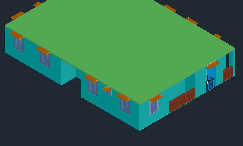
- Rendering is Done by adding materials to the 3D View
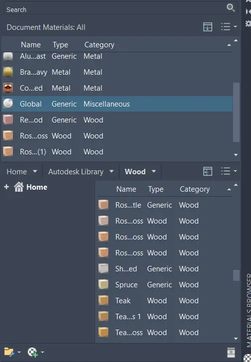
- Material Browser is used for adding Materials to Objects
- The Materials Added for the Components from the material Browser are Shown Below
Result: -