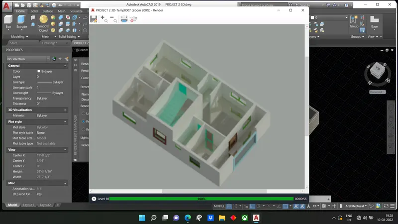
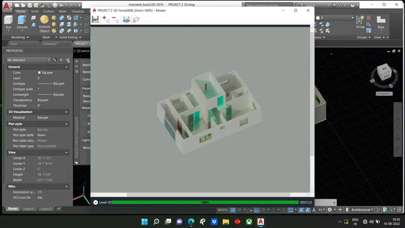
Project 2_Creating a 3D rendered model for a Residential Building in AutoCad
Question 1)
Answer:
Aim: To Create a 3D rendered model for a residential building in Autocad
Introduction: The main objective of this project is to understand about to create a plan in 2D then convert it into 3D using AUTOCAD 3D modeling and then apply materials and rendering.
AutoCAD is primarily used for generating 2D sketches. While it is possible to create 3D objects, AutoCAD is built around a flat sketch -based interface. 3D objects are cylinders, spheres and wedges and many more.We use 2D objects and modify them using 3D commands accordingly so we can use 3D commands like extrude, sweep, revolve and union.
Also, viewport command allows the user to split drawing area into different windows to project multiple views of the model.These include the top, front, left/right views of object. Some 2D and 3D tools which was used while working on this project as follows:
2D tools-
Line: The line object is most basic and common object in AutoCAD drawing of any disciple,Each segment is a line object that can be edited separately, assiginig properties such as layer, line type and line weight.
Construction Line
Polygon
Rectangle
Copy
Erase
Layers
Mirror
Offset
Extend
Move
Array
Fillet
Rotate
Dimension
Text
Fillet
3D tools:
Revolve- Draw>Modeling>Revolve
Extrude- Draw>Modeling
In AutocAD 3D extrude command allows the user to create a 3D object by extruding a 2D face along a line or path. For example, A cylinder can be created by selecting a 2D Circle and exruding a 2D face along a line or path. For example a cylinder can be created by selecting a 2D circle and extruding it along with a path.
Sweep
Draw > Modeling > Sweep
This command helps the user to extrude the 2D objects without the 2D face being orthogonal to the beginning of the path.
Union
Modify > Solids Editing > Union
This AutoCAD 3D command allows the user to combine two objects converting them into one single object.
Subtract
Modify > Solids Editing > Subtract
This command is opposite to the union command; this command works when there is a common area in both the objects. Then this command subtracts the object A from the object B.
Intersect
Modify > Solid Editing > Intersect
With this AutoCAD 3D command, the user is left with the area that is common to both the objects.
RENDERING
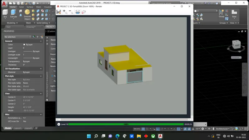
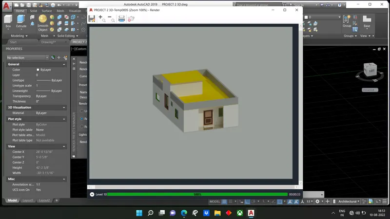
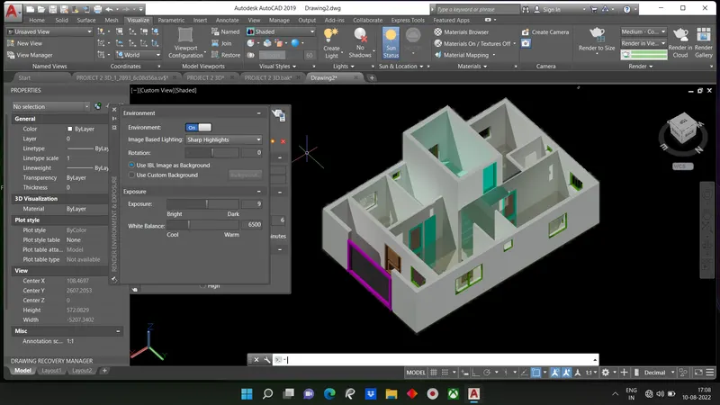
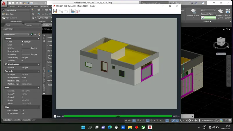
Rendering is the process of creating image based on the 3D objects in a scene. A renderer is used to calculate the appearance of the materials attached to the objects in a scene, and how lighting and shadows are calculated based on the lights placed in a scene. Environmental and exposure settings of the renderer can be adjusted to control the final rendered image.
Sizes of Windows and Doors
Door D- 4'6" x 7'0"
D1- 3'0" x 7'0"
D2-2'6" x 7'0"
Window W- 6'0" x 4'0"
W1- 5'0" x 3'0"
W2- 4'0" x 3'0"
Procedure:
Open AutoCAD
In start Up setting Start from scratch select Imperial
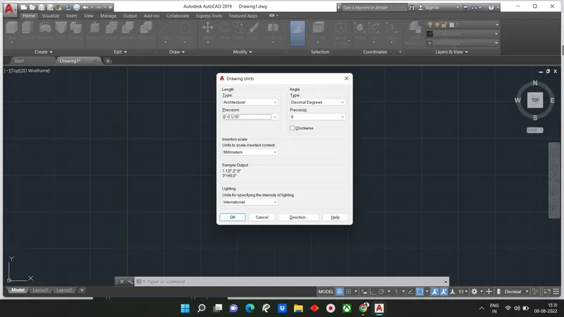
Type UN in command tab and press enter
Change Units type to decimal and precision to 0.00 and insertion scale to architectural
STEP-1: Creating Layers
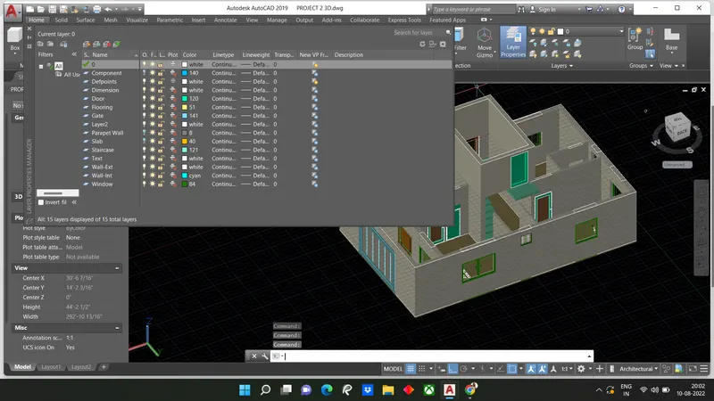
Open Layer properties and create new layers by clicking on new layer or right-click on any layer and select a new layer to create a new layer
Layers are created as follows
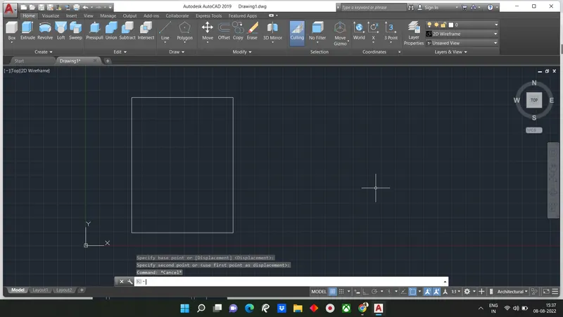
STEP-2: Create Plot
Type Rec in command tab
Specify the point as 25',40'
Close rectangle
STEP-3:
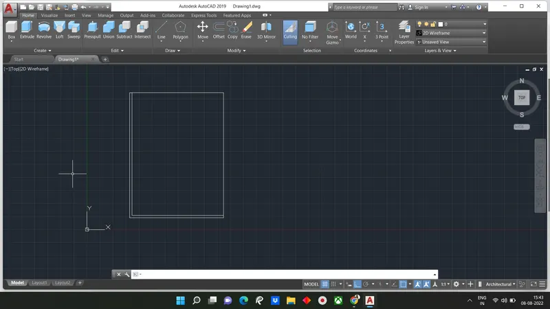
- In the command prompt write offset
- Specify offset distance as 9" for exterior wall and 4.5" for interior wall
- In the command prompt write L enter
- Specify first point and draw the bedroom and toilet part in the plan
STEP-4:
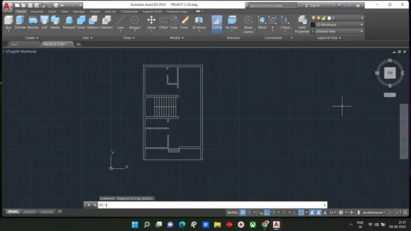
- Similarly draw all other rooms using Line command
- While drawing Staircase use copy command for treads(6" RISE & 1' TREAD)
STEP-5:
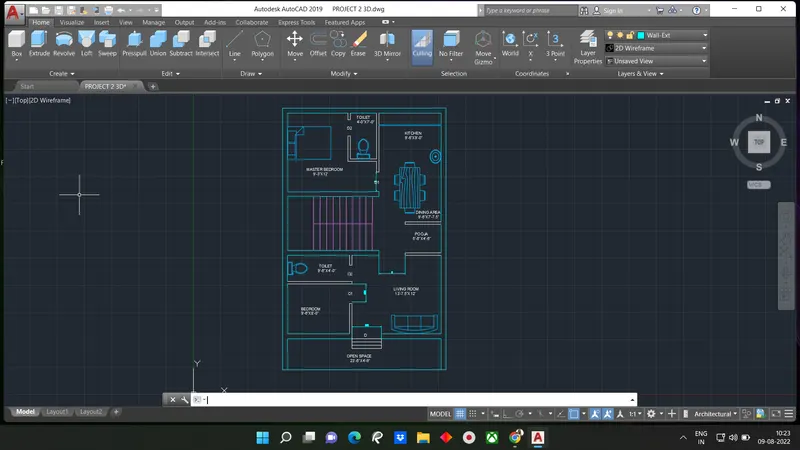
- By using Layer command allocate the properties in the suitable lines.
STEP-6:
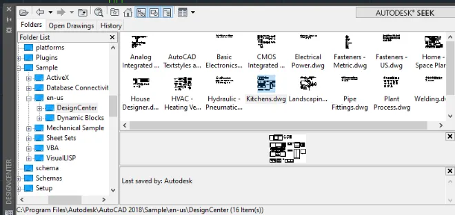
1) In the command prompt write DC
2) Select the suitable Component from the dialogue box for our plan
3) Drag the component into the plan area and place wherever necessary
STEP-7:
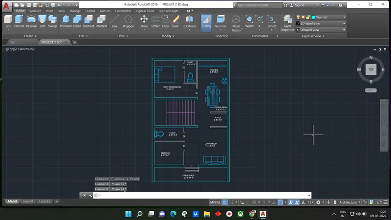
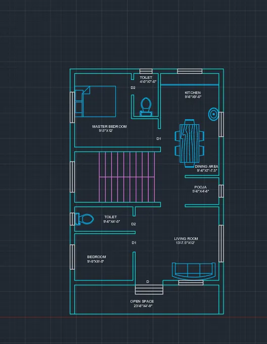
1) In the command prompt write TEXT
2) Write the text in the suitable area
3) In the command prompt write DIMLINEAR
4) Mark the dimension and complete the floor plan of the building
STEP-8:
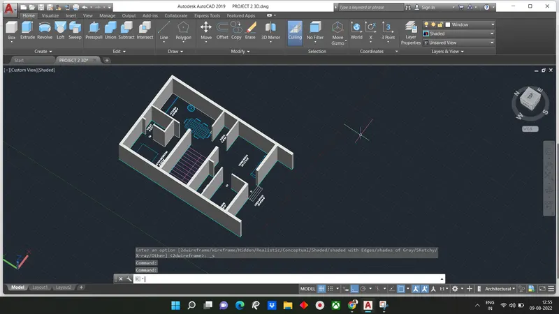
- Make the extrusion using Rectangle method
- In the command prompt write EXT
- Select Object
- Specify Extrusion height as 10'
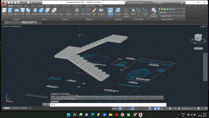
STEP-9:
- In the command prompt write L enter
- In the command prompt write 0,6"
- In the command prompt write 1',0 and close the line
- In the command prompt write Copy
- Select ARRAY
- Put 10 in the command box and join the base line to top
- In the command prompt write Join
- Select object and make all the line as poly line
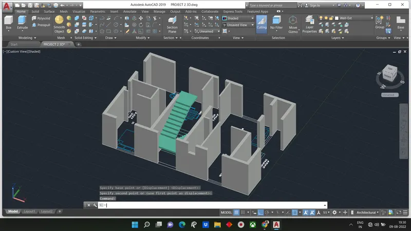
STEP-10:
Window space is presspull from wall portion
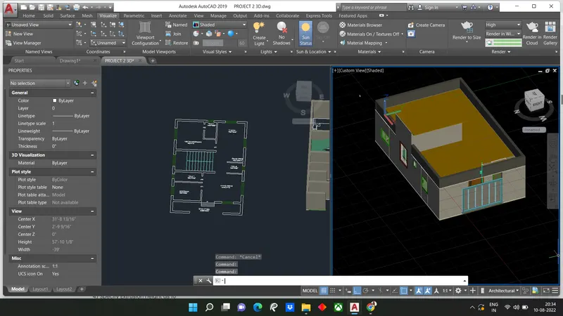
STEP-11:
- Click the icon of (-) in the drawing area
- Select 2 Vertical
- On the other side of the drawing area switch into the Isometric View
- Lock all the layer in the floor plan
STEP-12: Adding Doors to 3D model
Convert all types of doors into a 3D model blocks
Go to block editor and add rotate parameters and rotate action to all the door types
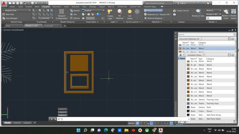
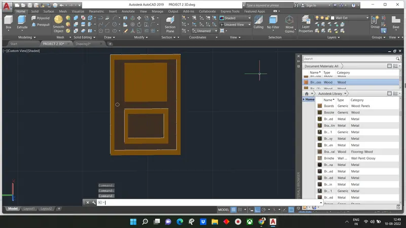
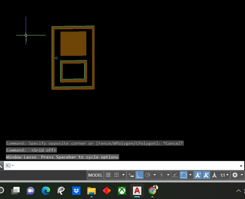
- Door D :
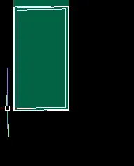
A model door as shown in figure is drawn with dimensions 4'6" x7'0"
Using line, circle and presspull command we draw door
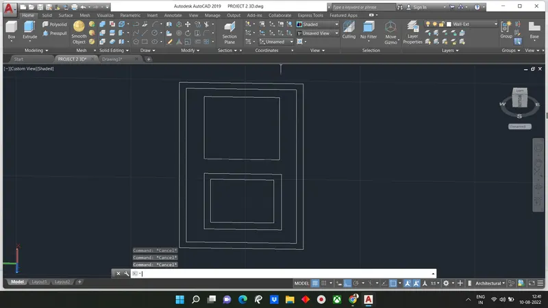
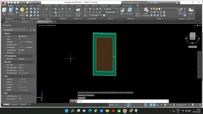
D1: 3'0" x 7'0"
Use line tool and rec , offset to draw door
Using Visualize>Material option we can give any material to door
D2: 2'6" X 7'0"
STEP-13: Creating Windows
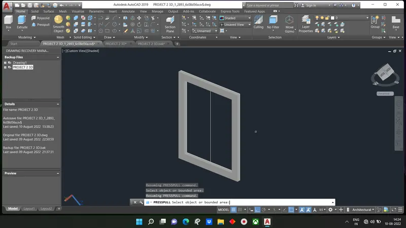
i. Window 1
Change the current layer to Window Frame
- Draw a window of dimension 5'X4'
- Offset the rectangle to inside distance of 6"
- Offset the same to a distance of 3" to inside
- Draw a line connecting midpoints of the inner rectangle
- Offset the same to a distance of 1" to inside
- Circle at mid inside in both side
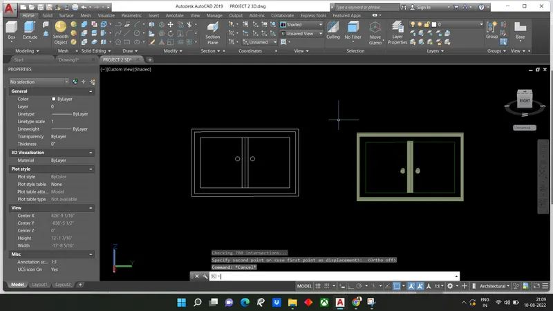
Draw other window using similar line , offset, rec, circle command.
W: 6' x 4'
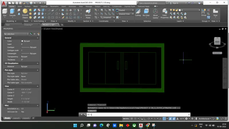
W2: 4'-0" x 3'-0"
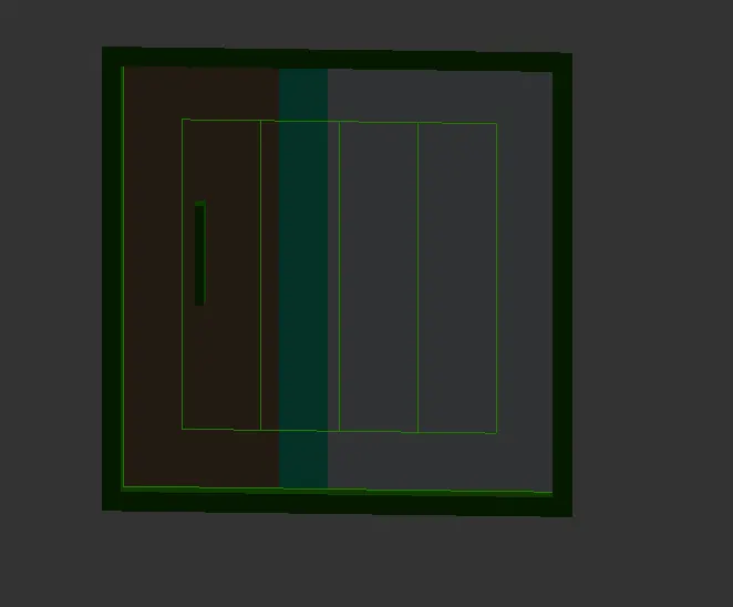
V: Ventilation 2'-0"x1'-0"
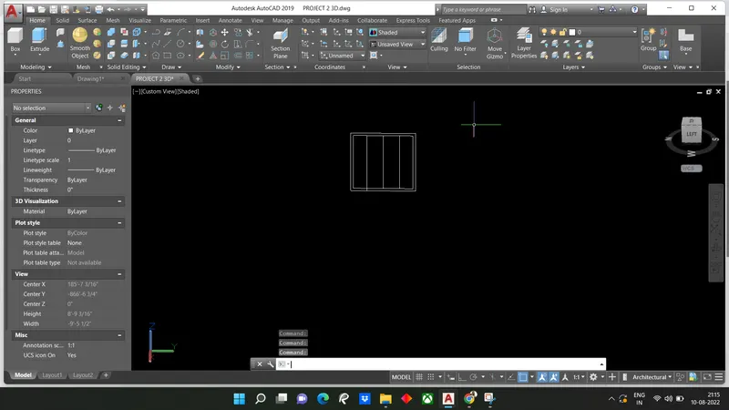
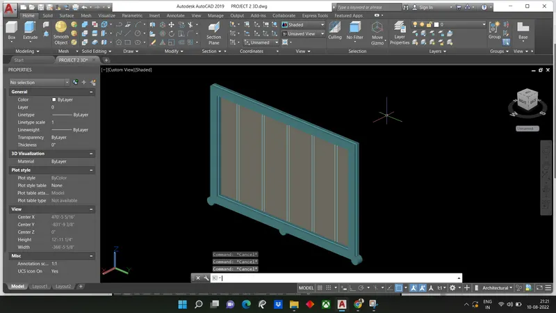
STEP-14: Creating Gate for Outside Open space
CReating a gate like portion with some distance and presspul its outer portion with some distance and provide plastic material in between that
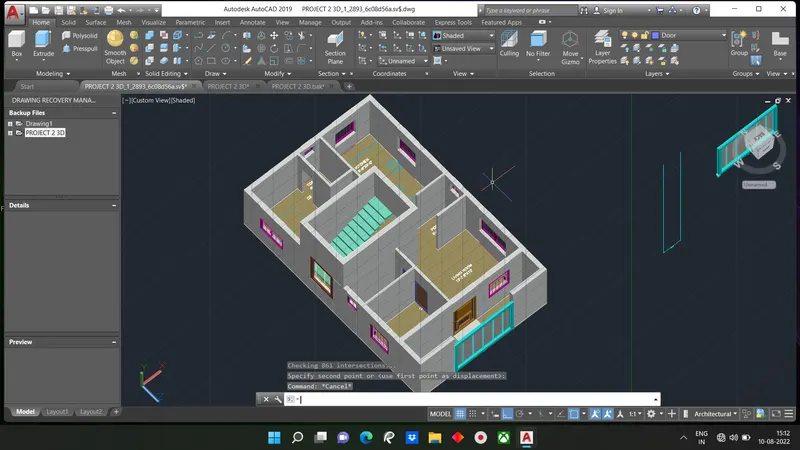
STEP-15: Creating Flooring at Base
- In the command prompt write Presspull
- Select the first copied object and presspull it at some distance
- Close the presspull command
- In the command prompt write Copy
- Select the source object and paste it at top of the object we created
- Close the copy command
STEP-16: Creating Tower
Using presspull tool create tower portion at staircase at height of 7'
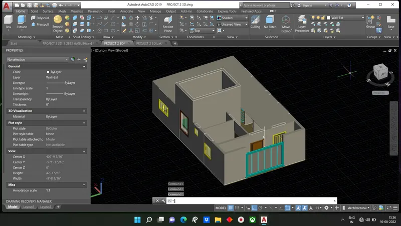
STEP-17:Top Slab
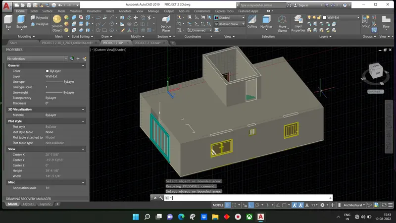
STEP-18: Parappet Wall
- In the command prompt write Layer
- Create a new layer and name it as Parappat
- Choose the suitable colour and set current layer
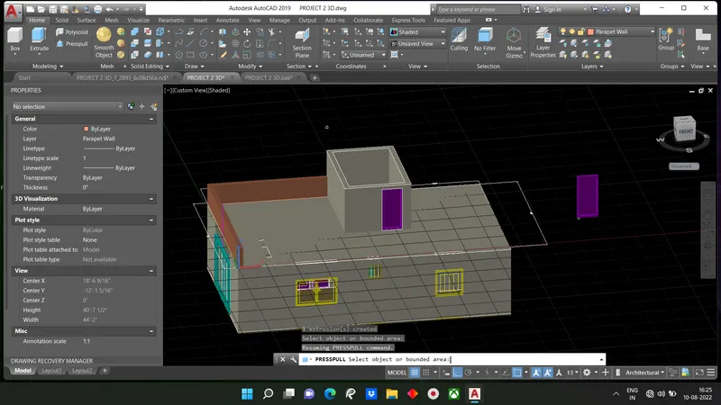
- In the command prompt write offset
- Specify offset distance as 31 (Wall thickness)
- Offset the parappat object and write Presspull in the command prompt
- Presspull it at some distance and close the command
- In the command prompt write copy
- Select source object and paste it on top of the slab object
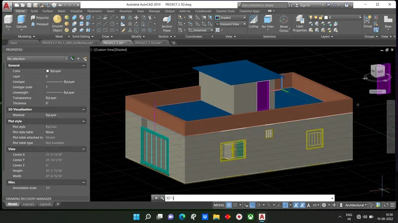
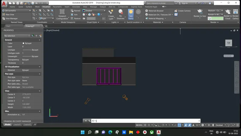
STEP-19: Elevation of the building
FRONT VIEW:1
SIDE VIEW
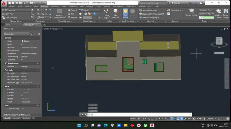
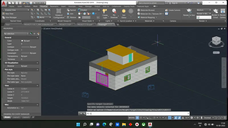
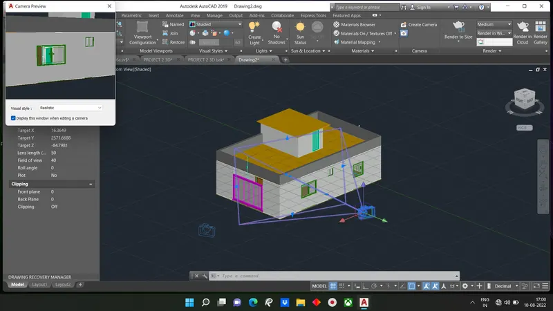
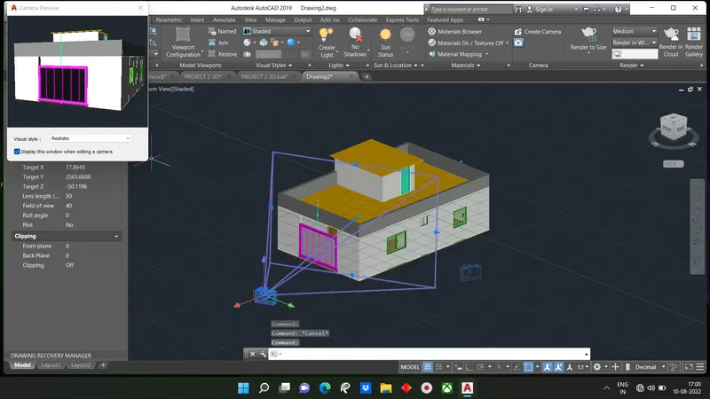
Rendering part: Using Camera
- In the command prompt write Camera
- Select Name and name it as View 1
- Place the camera and set the viewing angle
- similarly do this for another camera and name it as view 2
View 1
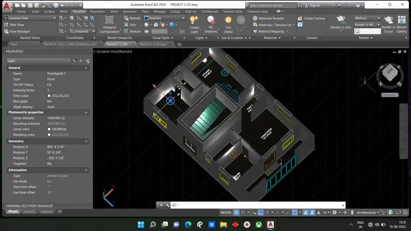
STEP-20: Light Affect
Sun affect
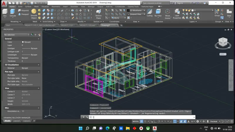
2D Wireframe
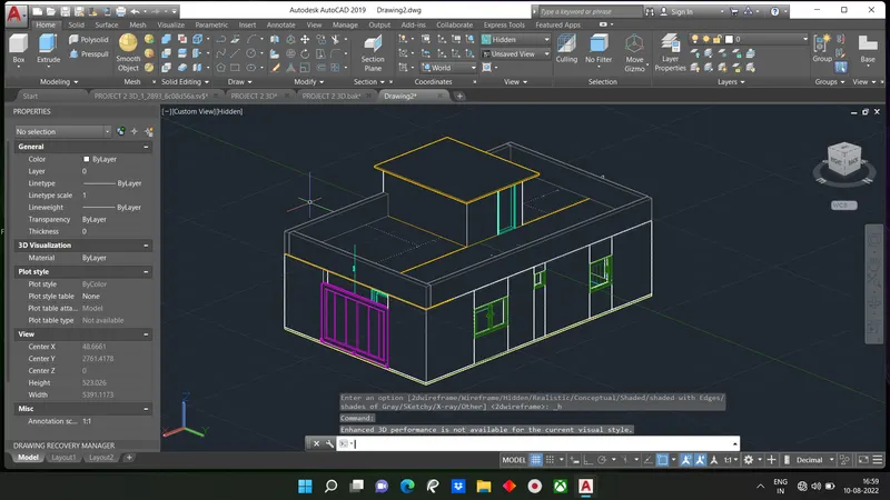
Hidden View
Result:
The project aims to draw a rendered view of a residential building. Initially, Layers are created in step 1. Then plan view of the residential building is drawn which is the same for all floors as shown in step 2. After that drafting and annotation settings are changed to 3D Modelling advanced for drawing a 3D view of the plan. From step 3, a 3D view of the residential building floor plan and extrusion of walls is done. In the next step 3D view of components of the building such as the staircase, doors and windows are drawn. In the next steps adding components to the building and created superstructure is done. In step 6 different views are created to show the result of the project. In the final step of the procedure, 3D Rendering process for the residential building and all the assigned materials are shown for both superstructure and also components of the building separately as most of them are not visible in the superstructure.