Drafting of various geometries using Chamfer, Fillet tool in AutoCad
Drafting of various geometries using chamfer, Fillet tool in Autocad
Drawing-1
Aim:
To determine drafting of various geometric using Chamfer, fillet tool in autocad
Introduction:
- Autocad offers various tools to perform different tasks. The various tools which are used for drafting in.
- This Project are briefly described here.
These tools include-
Modification tools: Chamfer,, fillet , offset, rotate, object snapping, trim and extend, Lengthen, Mirror and join
CHAMFER:
- A bevel or chamfer is:
An angled line that meets the endpoints of two straight 2D objects.
A Sloped transition between two surfaces or adjacent faces on a 3D solid
- The distances and angles that you specify are applied in the order that you select the objects.
Command Used: Chamfer
FILLET:
- The fillet tool helps form round corners between any two entities that form a sharp vertex.
- A round or fillet can be created between two objects of the same or different object types: 2D polylines, arcs, Circles, ellipses, elliptical arcs,lines, rays, splines, Xlines.
- If the two selected objects are on the same layer, the arc defined is created on that layer. Otherwise, the arc is created on the current layer. The layer affects object properties including colourand line types.
OFFSET:
- Create concentric circles, parallel lines and parallel curves.
- Command used: OFFSET 'O'
ROTATE:
- Used to rotate object in our drawing around aspecifiesd base point.To determine the angle of rotation, we can enter an angle value, drag using the cursor, or specify a reference angle to alignto an absolute angle.
- Command Used: ROTATE
OBJECT SNAP:
- Object snaps provide a way to specify precise locations on objects whenever you are prompted for a point within a command
- For example, you can use object snaps to create a line from the centre of a circle to the midpoint of another line. The available options are endpoint (end), midpoint(mid), centre(cen), geometric centre(gcen), nearest(nea), quadrant of circle(quad), intersection, perpendicular, tangent,parallel, extension, apparent intersection nodes, insertion points.
- Command Used: OS-Object Snap
TRIM and EXTEND:
- Trims objects to meet the edges of other objects
- Quick Mode.To trim object select the objects to be trimmed individually press and drag to start a freehand selection path, or pick two empty locations to specify a crossing fence.All object automatically act as cutting edges. selected objects that can't be trimmed are deleted instead.Standard mode To trim objects first select the boundaries and press enter. Then select the object to be trimmed. To use all objects as boundaries press enter at first select objects prompt.
- Command Used: TR
- Extends objects to meet the edges of other objects.To extend objects, first select the boundaries then press enter and select the objects that you want to extend.To use all objects as boundaries.Press enter at the first select object prompt.
- Command Used: EX
LENGTHEN:
- Changes the length of objects and the included angle of arcs.
- You can specify changes as a percentage, an increment or as a final length or angle. LENGTHEN is alternative to using TRIM or EXTEND
- Command Used: Lengthen
MIRROR:
- Create a mirrored copy ofselected objects
- We can create objects that represent half of a drawing select them and mirror them across a specified line to create the other half.
- Command Used: MIRROR
JOIN:
- Joins the endpoints of linear and curved objects to create a single object. Combines a series of finite linear and open curved objects at their common endpoints to create a single 2D or 3D object. The types of object that results repends on the types of objects selected the types of object selected first and whetherthe object are coplanar.
- Command used:MIRROR
Procedure:
STEP-1:
i) Open the AutoCAD software and Click on new drawing sheet.
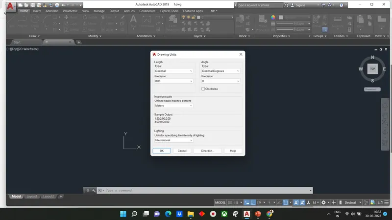
ii) Enter UNITS in command box
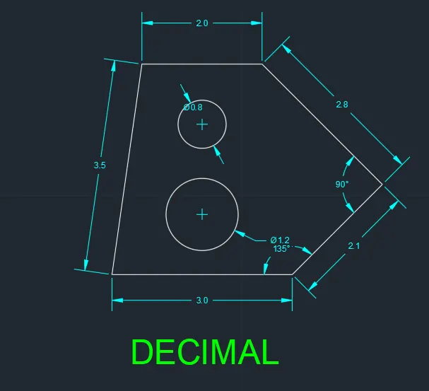
iii) Select DECIMAL in type, 0.00 in PRECISION and Meters in UNITS to scale inserted content Press OK.
STEP-2:
i) Turn off the ortho mode
ii)L for the line command
iii) Set the coordinate of origin as 0,0
iv) Drag the mouse rightwards
v) Type 3 as length of line and press enter
vi) Press escape
STEP-3:
i) Type OS in the command bar for object snap
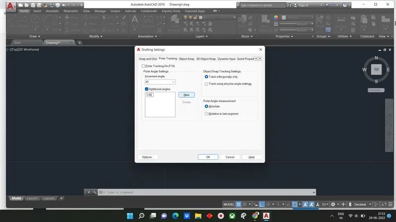
ii) Go to polar tracking settings in the dialogue box.
iii) There change the angle increment as 45 degree and can also add 135 degree in additional angle option.
iv) Also keep polar tracking mode
v) Then back to drawing sheet and L for the line command
vi) Start the line from the right end of the previously drawn line
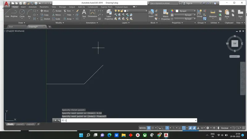
vii) Drag the mouse upwards and then polar tracking shows the135 degree angle indication as a dotted green line.
viii) Then type 2.12 in command bar as the length to line and press enter key.
STEP-4:
i) For the next line drag the mouse slightly left.
ii) As the angle increment is 45 degrees it indicates the 45 degree angle just as in the previous figure.
iii) Then type 2.83 in the command bar as the length to line and press enter key.
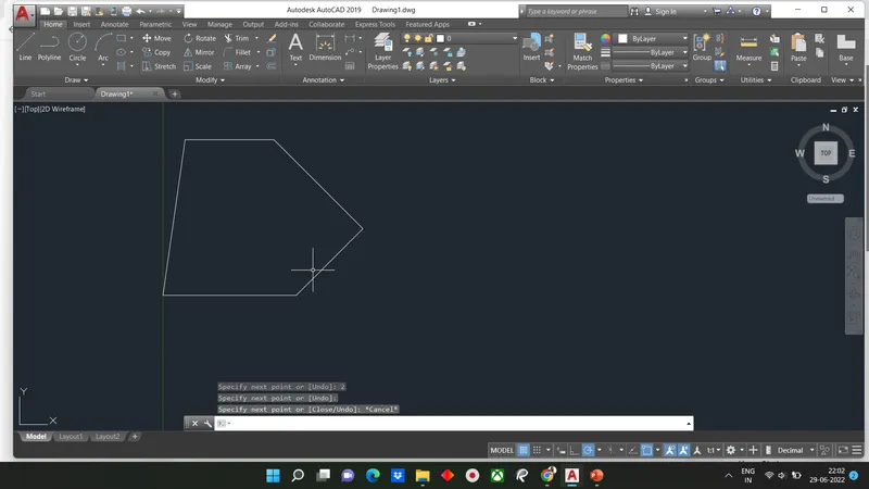
STEP-5:
i) This time turn on the ortho mode using F8 key or from the status bar.
ii)Type 2.00 as the length of line in command box
iii)Press enter
STEP-6:
i) Typing C and enter key will enclose the figure
ii) Press escape
STEP-7:
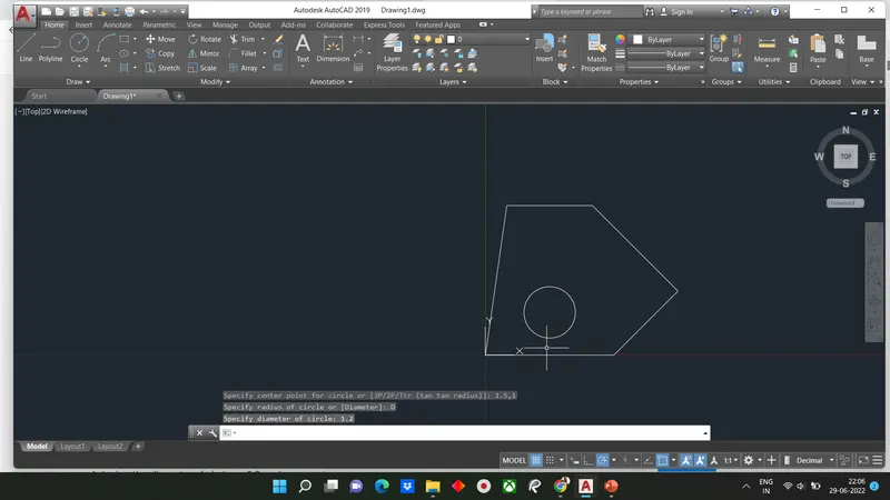
i) Now type C or circle in the command box for circle
ii) Now Type 1.5,1 as centre of circle and press enter key.
iii) Now in the command bar type D for diameter of circle
iv) Assign the diameter of circle as 1.20 and press enter
STEP-8:
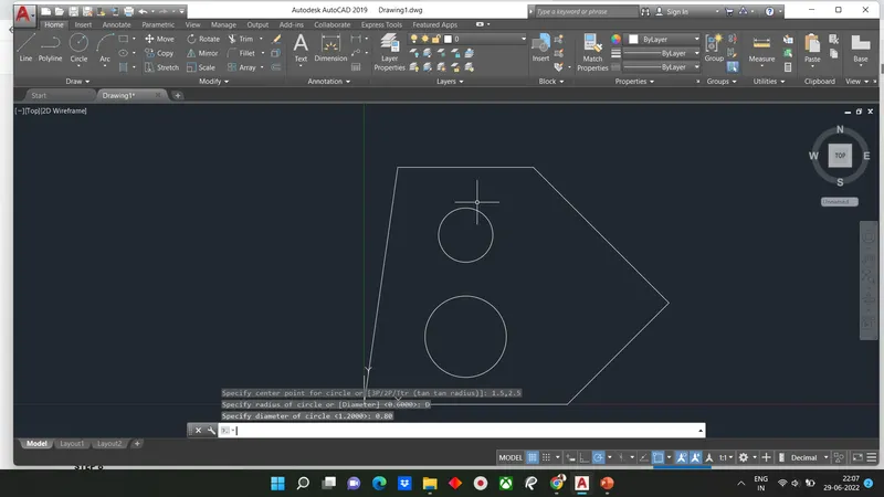
i) Now type C or circle in the command box for circle
ii)Now type 1.5,2.5 as centre of circle and press enter key
iii)Now in command bar type D for diameter of circle
iv)Assign the diameter of circle as 0.8 and press enter
STEP-9:
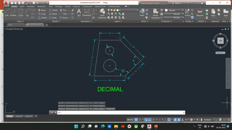
i)Enter DIMS in command box
ii)Click Modify
iii)Click SYMBOLS and ARROWS. Enter 0.05 in arrowsize
iv)Click TEXT Enter 0.05 in Text height
v)Click Ok
vi)Select STANDARD in style.Click SET CURRENT .Click Close
vii)Enter DIM in command BOx
viii)Click the first point and second point of the object. Drag it to the desired loaction.The dimension will be fixed in the preferred location in worksplace.
ix) Drag the dimension fall the objects in the workspace which arelocated in given diagram
RESULT:
Drawing-2
Aim: To draw the geometry using direct distance entry method.
Introduction: We can draw the given geometry using AUTOCAD tools
- Autocad offers various tools to perform different tasks. The various tools which are used for drafting in.
Procedure:
STEP-1:
i) Open the Autocad software and click on new for a new drawing sheet
ii) Enter UNITS in command box
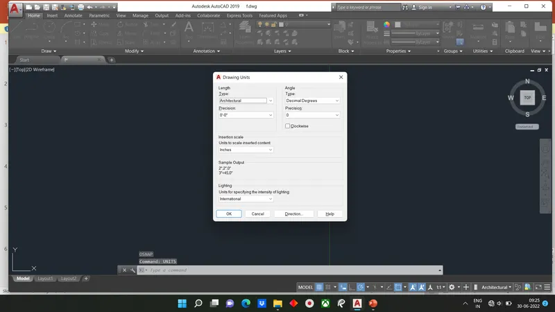
iii) 0'0.0" in Precision and Inches in UNITS to scale inserted Press OK
iv) Also Select Engineering in Dimension Style(Give command DIMSTYL)
STEP-2:
i) Before start drafting ortho mode turned off
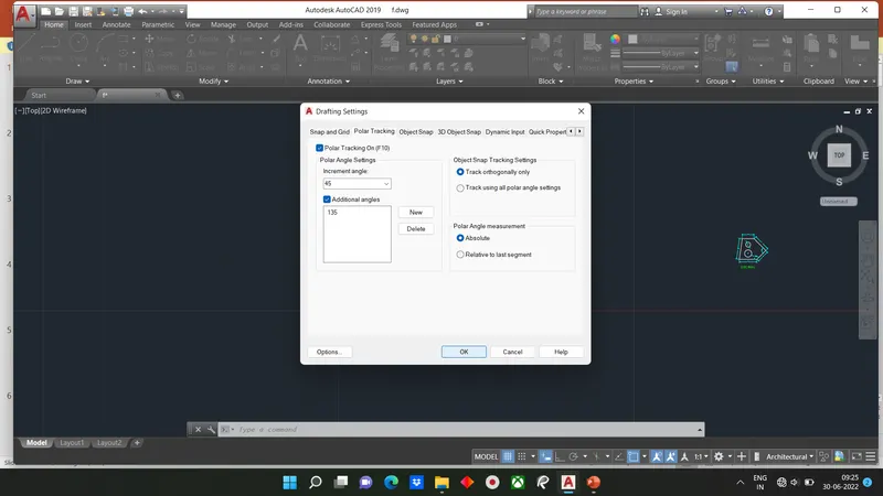
ii) Type OS in the command bar for object snap
iii) Go to polar tracking settings in the dialogue box
iv)There changes the angle
STEP-3:
i) L for the line and type 0,0 as origin and enter
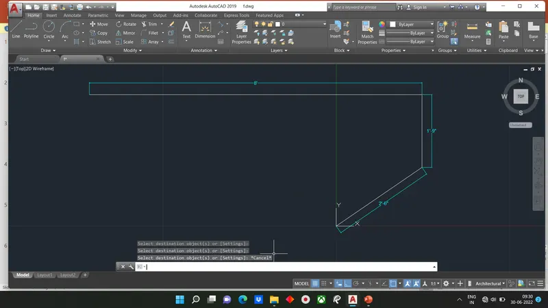
ii) Drag the mouse upwards and then polar tracking shows the 45degree angle indicationas a dotted green line
iii) Then type 2'10" in the command bar as the length to line and press enter key.
STEP-4:
i) Turn on ortho mode(F8)
ii) Now drag mouse upwards
iii) Typpe length as 1'9" in command box
iv) Press enter
STEP-5:
i) Keep ortho mode on
ii) Drag mouse leftwards
iii) In the command box types 8' as the length of line
iv) Press enter
STEP-6:
i) Keep ortho mode on
ii)Drag mouse downward
iii)In the command box type 2'5" as the length of line
iv) Press enter
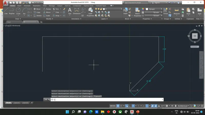
STEP-7:
i) Turn off Ortho mode
ii) Then type @3'<300 in command bar as the length to line and angle
iii) Press enter key
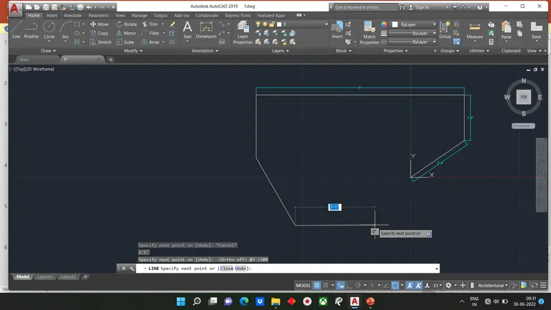
STEP-8:
i) Then type @2'6"<30 in command bar as the length to line and press enter key.
ii) And in command box type C and enter
STEP-9:
i) Enter DIMS in command box
ii) Click modify
iii) Click symbols and arrows. Enter required size of arrow
iv)Click TEXT.Enter 0.05 in Text height
v) Click ok
vi)Select STANDARD in style Click SET CURRENT. Click Close.
vii)Enter DIM in command box
viii) Click the first point and second point of the object,Drag it to the desired location.The dimension will be fixed in the preferred location in workspace.
ix)Drag the dimension of all objects in the workspace which are loacted in the given diagram.
RESULT:
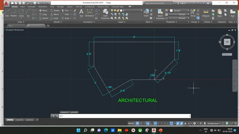
DRAWING-3
Aim: To draw given geometry using AUTOCAD
Introduction: Drafting the given geometry using chamfer, circle
- Autocad offers various tools to perform different tasks. The various tools which are used for drafting in.
Procedure:
STEP-1:
i) Go to start menu, select AUTOCAD 2022
ii) In command line type in: STARTUP(Enter)
iii) Enter new value of startup:1
iv) Go to application Menu and select New
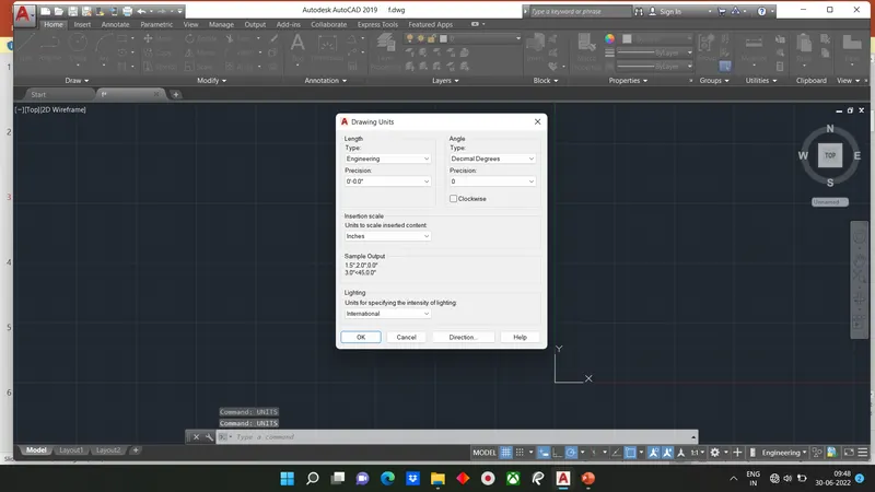
v) In the 'create new drawing dialog box' we do the advanced setup and select engineering unit of measurement and select precision as 0'-0.0"
vi) Enter 'UNITS' command in command tab
vii) In the drawing units dialog box, select Engineering in type; 0'-0.0" in precision and inches in insertion scale.
viii) Click on -ok
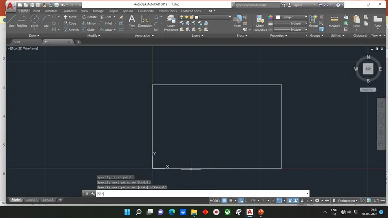
STEP-2:
i)Select the line tool by entering "Line" command in the command tab
ii)Specify the first point as 0'0",0'0" in the command line
iii)Specify the coordinate of nest point as @5'0.1",0'0"
iv)Specify the coordinate of next point as @0'0",3'3"
v) Specify the coordinate the next point as @-5'0.1",0'0"
vi) Click Close on the command line
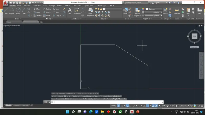
STEP-3:
i) Select the chamfer tool by entwring 'Chamfer' command in the command tab
ii)Select first chamfer line
iii)Specify the Distance option on the command line
iv)Specify the first chamfer distance as 19.0"
v)Specify the second chamfer distance as 25.6"
vi)Then select the second line
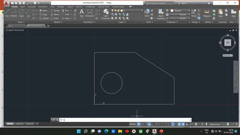
STEP-4:
i) Select the circle tool by entering CIRCLE command in command tab
ii) Specify the centre point of circle as 13.0",16.0" in command line
iii)Select the diameter option in command line
iv)Specify diameter of circlr as 16.0"
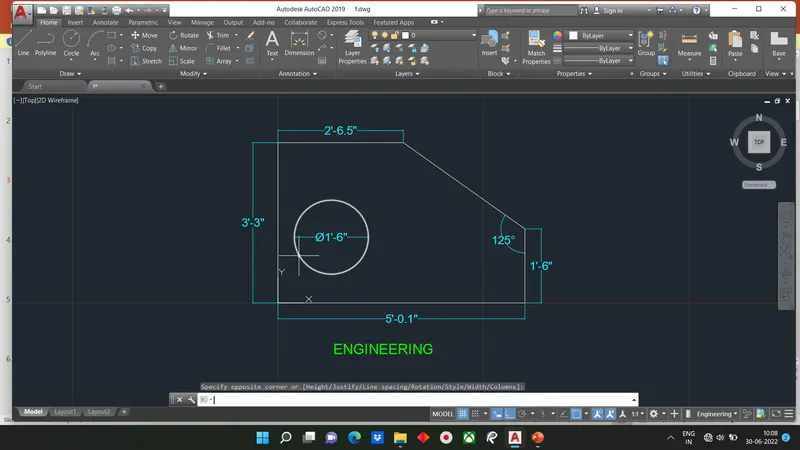
STEP-5:
i) Enter DIMS in command box
ii) Click modify
iii)Click Symbols and Arrows Enter 0.05 in arrow size
iv)Click TEXt enter 0.05 in Text Height
v) Select standard in style click SET CURRENT Click close
vi) Enter Dim in command box
vii)Enter DIM in command box
viii) Click the first point and second point of the object.Drag it to desired location.The dimension willbe fixed in the preferred loaction in workspace.
RESULT:
After following above steps and providing dimension we got result
DRAWING-4:
Aim: Drafting the given figure using chamfer or fillet or line or object snap options
Introduction: The given geometry in cretaed in AUTCAD using primarily the line tool.The procedure of drawing is explained in detail with diagrams of each step and final result is given.
Procedure:
STEP-1:
i)Go to Start Menu, Select AUTOCAD
ii)In command line type:STARTUP(ENTER)
iii) Enter new value of startup:1
iv)Go to application Menu and Select New
v) In create new drawing dialog box, we do the advance setup and select the DECIMAL unit of measurement
vi)Enter UNITS command in the command tab
vii)In drawing units dialog box is there, select decimal in Type '0.00'in precision and meter in insertion scale
viii)Click on ok
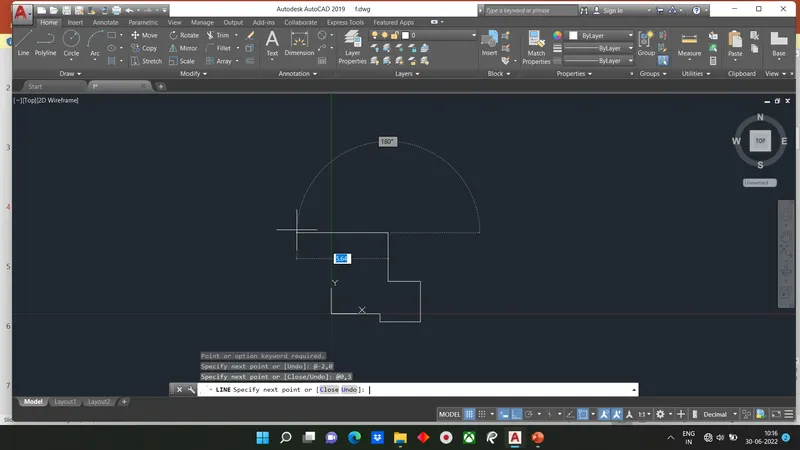
STEP-2:
i)Select the line tool by entering LINE command in the command tab
ii)Specify the first point as 0,0 in the command line
iii)Specify the coordinate of next point as @3,0 in command line
iv)Specify the coordinate next point as @0,-0.50 in command line
v) Specify the coordinate of next point as @2.50,0 in command line
vi)Specify the coordinate of next point as @0,2.5 in command line
vii)Specify the coordinate of next point as @-2,0 in command line
viii)Specify the coordinate of next point as @0,3 in command line
ix)Specify the coordinate of next point as @-2.50,0 in command line
x)Specify the coordinate of next point as @0,-2 in command line
xi)Specify the coordinate of next point as @-1,0 in command line
xii)Click close
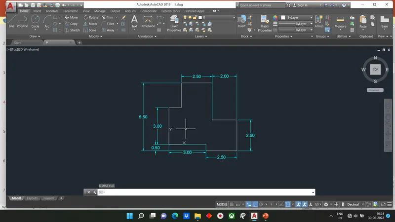
STEP-3:
i)Enter DIMS in command box
ii)Click Modify
iii)Click SYMBOLS and ARROW Enter 0.05in arrow size
iv)Click TEXT Enter 0.5 in text height
v)Click ok
vi)Select STANDARD in style Click SET CURRENT Click close
vii)Enter DIM in command box
viii)Click the first point and second point of the object drag it to the desired loaction. The dimension will be fixed in the preferred location in the workspace.
ix)Drag the dimension of all the objects in workplace which are located in given diagram
RESULT:
DRAWING-5:
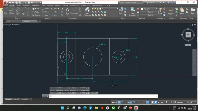
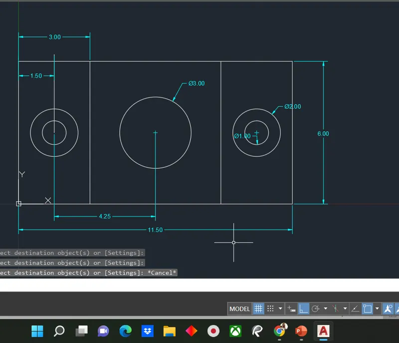
Aim: To draw given geometry 5
Introduction:
- Autocad offers various tools to perform different tasks. The various tools which are used for drafting in.
Procedure
Step-1:
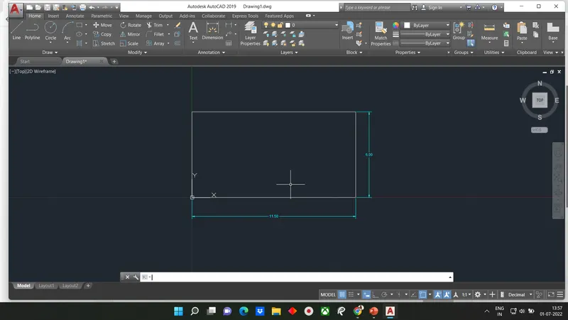
i) Open the AutoCAD software and click on new for a new drawing sheet
ii) Enter UNITS in command box
iii) Select Decimal in type 0.00 in precision and meter in unit to scale inserted content Press ok
iv)Switch on orthomode
v) Enter L in command box
vi)Enter 0,0 as first point
vii)Enter @11.50,0 as next point
viii)Enter @0,6 as next point
ix)Enter @-11.5,0 as next point
x)Enter @0,-6 as next point
xi)Press Enter or click close
STEP-2
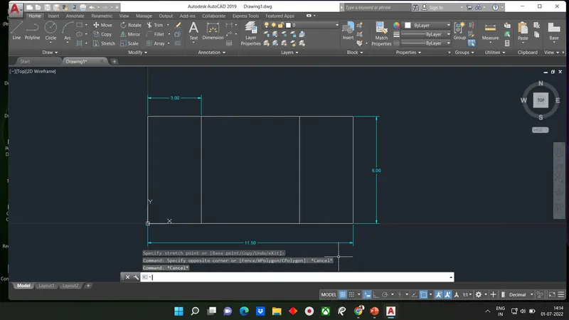
i)Enter o in command box
ii)Enter 3 as offset distance
iii)Select left line and drag it at 3 distance
iv)Select right line and drag it at 3 distance
v)Press enter or click Exit
STEP-3
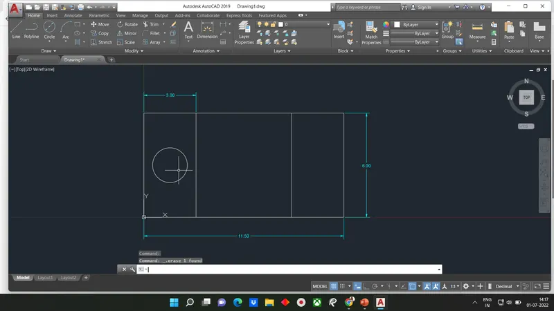
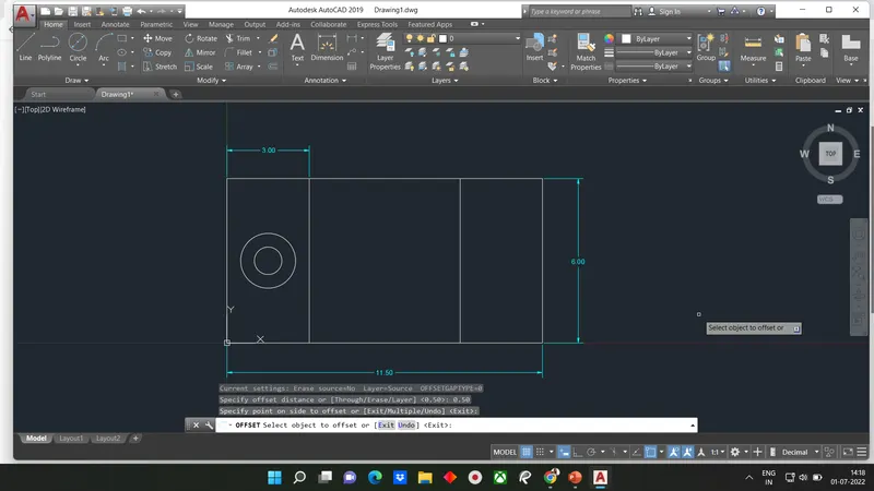
i)Click circle Diamter in ribbon
ii)Enter 1.5,3 as centre point for circle
iii)Enter 2 as diamter of circle
iv)Enter o and click layer
v)Click source and enter 0.50 as offset distance
vi) Select the circleand click point inside the circle
vii)Press Enter or Click Exit
STEP-4
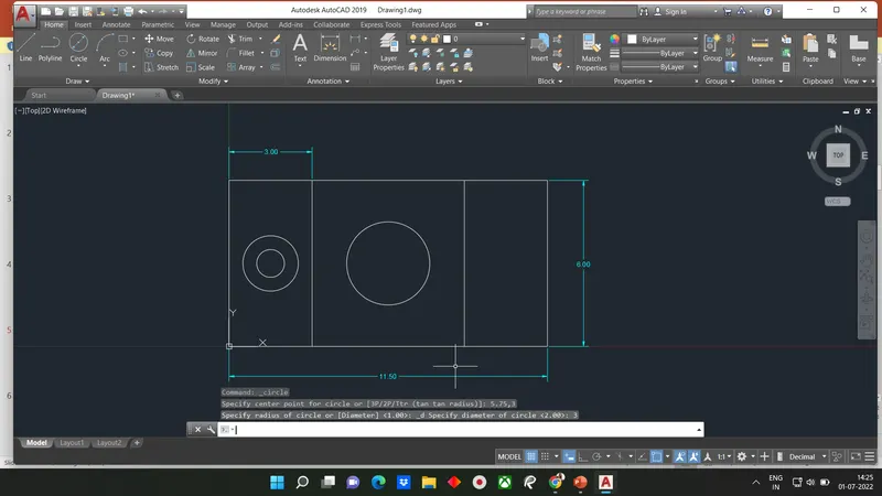
i)Click Circle Diameter in ribbon
ii)Enter 5.75,3 as centre point for circle
iii)Enter 3 as diamter of circle
STEP-5
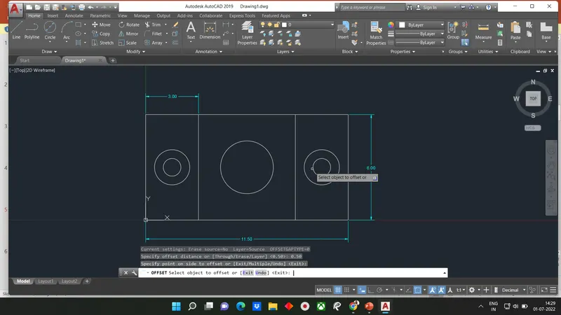
i)Click Circle, Dimater in ribbon
ii)Enter 10,3 as centre point for circle
iii)Enter 2 as diameter of circle
iv)Enter 0 and click layer
v)Click Source and enter 0.5 as offset distance
vi) Select the circle and click point inside the circle
vii) Press Enter or click Exit
STEP-6
i)Enter DIMS in command box
ii)Click modify
iii)Click SYMBOL and ARROW Enter 0.05 inarrow size
iv)Click Text.Enter 0.05 in arrow size
v)Click ok
vi)Select Standard in style, Style SET CURRENT, Click Close
vii)Enter DIM in command box
viii)Click the first point and second point of the object,Drag it to the desired location.The dimension will be fixed in the preferred location in the workspace.
ix)Drag the dimension of all the objects in the workspace which are located in the given diagram
DRAWING-6:
Aim: To create the given geometrical figure using autocad
Introduction: The geometry 6 unit using AUTOCAD iscreated by lines.The procedure and result should be written after creating the geometry 6.
Procedure:
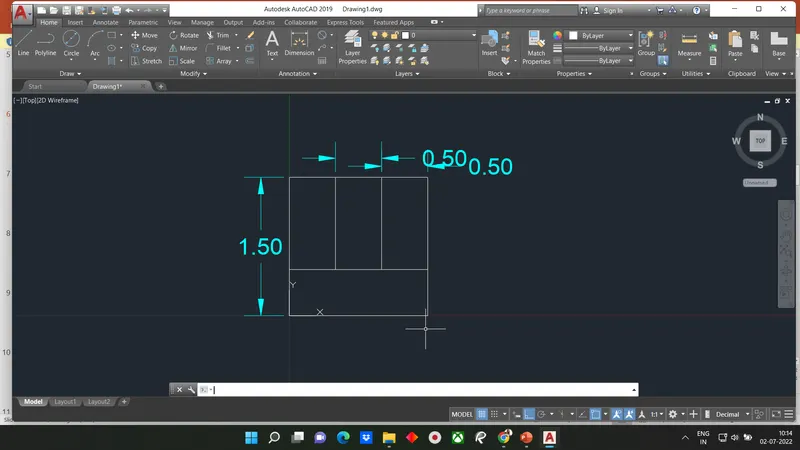
STEP-1 for Drawing 1:
i)Open AutoCad software and click start drawing tab
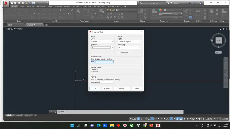
ii)Enter UNITS in command box
iii)Select DECIMAL in type 0.0 in precision and Meter in UNITS, press ok
iv)Switch on orthomode
v)Enter L in command line
STEP-2 for Drawing 1:
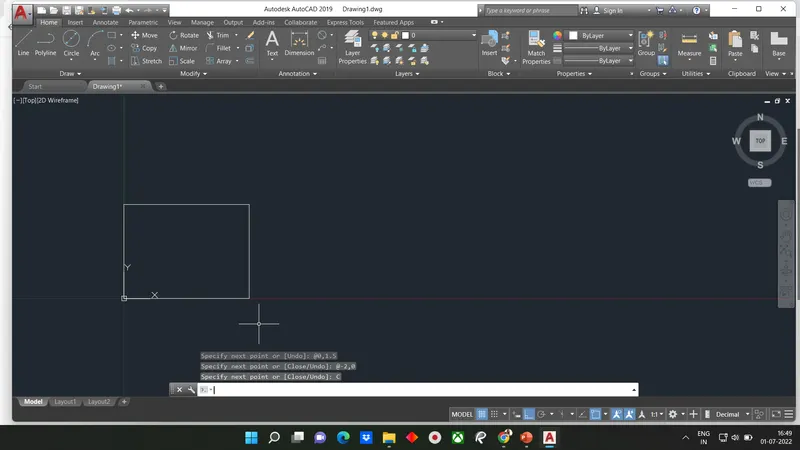
i)Enter 0 as first point
ii)Enter @2,0 as next point
iii)Enter @0,1.5 as next point
iv)Enter @-2,0 as next point
v)Enter @0,-1.5 as next point
vi)Press Enter
STEP 3 For Drawing 1:
i)Enter 0 and 0.5 as offset distance
ii)select the line and drag it as 0.5 distance
iii) Select the upper line and drag it at 0.5 distance
iv)Press Enter or click Exit
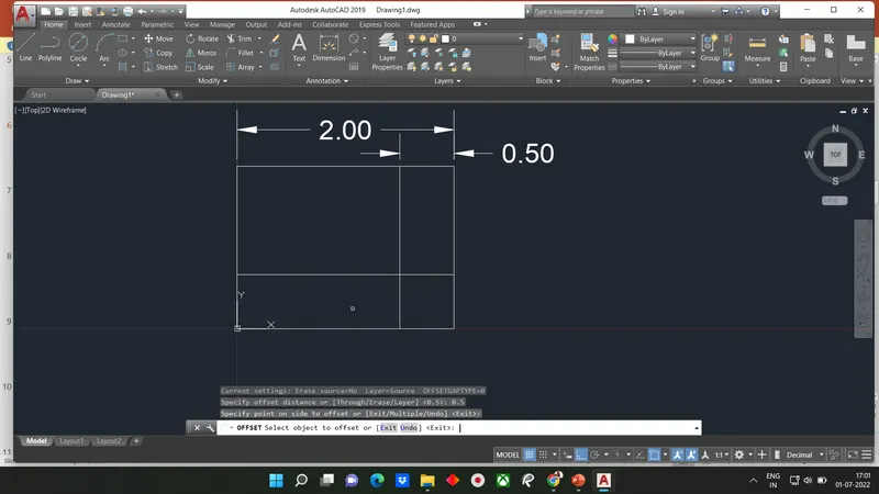
STEP 4 For Drawing 1:
i) Enter TR and press Enter
ii) Click Edge and Extend
iii) Click the extruded line
iv) Press Enter
STEP5 5 For Drawing 1:
i)Enter DIMs in command box
ii) Click modify
iii) Click Symbols and Arrows enter required size
iv)Click Text Enter text height
v) Click Ok
vi)Select Standard in style, click SET CURRENT click Close
vii)Enter Dim in command box
viii)Click the frist point and second point of object .Drag it to the desired location.The dimension will be fixed in preferred location in workspace
ix) Drag the dimension of all the object in workspace which are loacted in given diagram
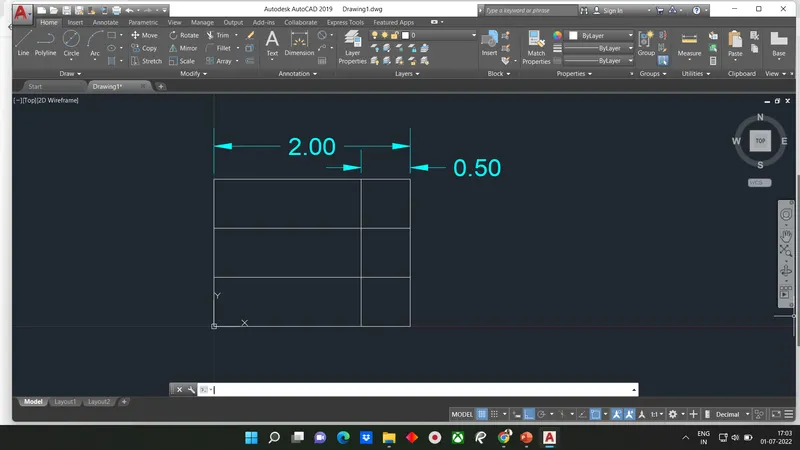
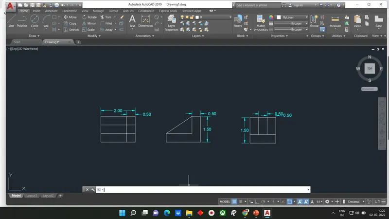
STEP 1 For Drawing 2:
i) Enter L in command box
ii)Enter 0,0 as first point
iii)Enter @2,0 as next point
iv)Enter @0,1.5 as next point
v)Enter @-2,0 as next point
vi)Enter @0,-1.5 as next point
vi)Press Enter or click Close
vii)Offset o @0.5 from downside & side
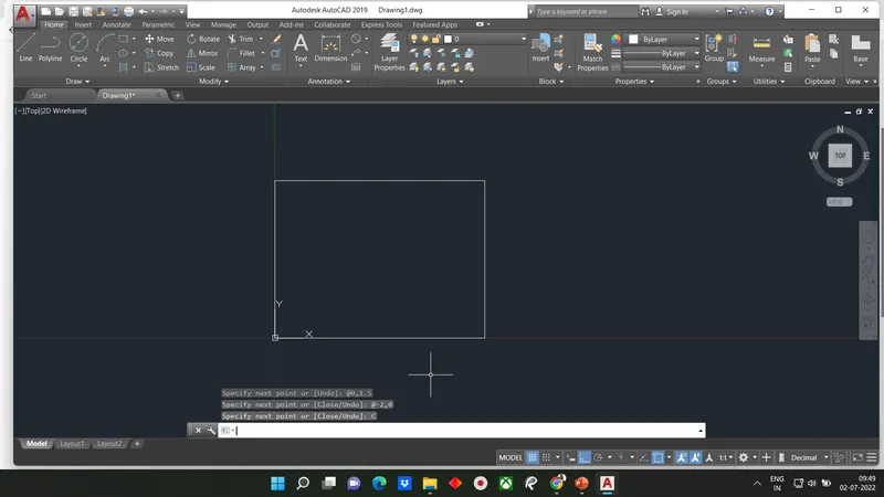
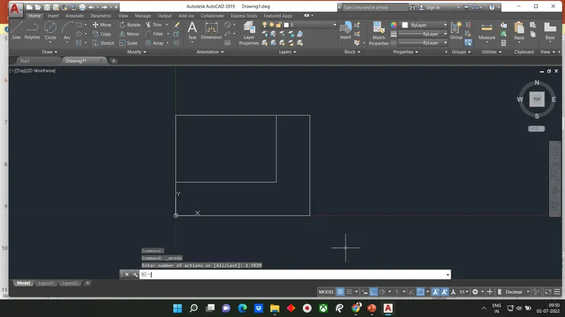
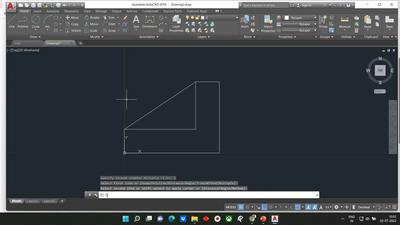
STEP 2 For Drawing 2;
i)Specify the two chamfer distance using DIMLIN
ii)Enter CHA and click Distance
iii)Enter 1.5 as first chamfer distance
iv)Enter 1.0 as second chamfer distance
v)Select the first line
vi)Select the second line
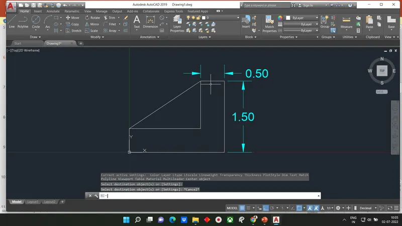
STEP 3 For Drawing 2:
i) Enter Dimlin
ii)Press Enter
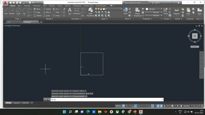
STEP 1 For Drawing 3:
i) Enter L in command Box
ii) Enter @0,0 as first point
iii)Enter @1.5,0 as next point
iv)Enter @0,1.5 as next point
v)Enter @-1.5,0 as next point
vi)Enter @0,-1.5 as next point
vii)Press Enter
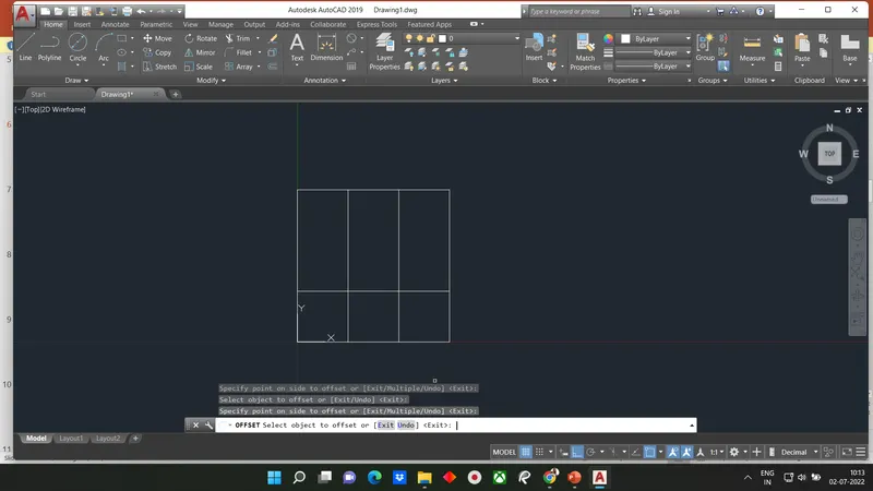
STEP 2 For Drawing 3:
i)Enter o and 0.5 as offset distance
ii) Select the lowest horizontal line and drag it at 0.5 distance
iii)Select the vertical line and drag it at 0.5 distance two time
iv)Press enter
STEP 3 For Drawing 3:
i)Enter TR in command Box
ii) Click Edge and Extend
iii)Select extruded line
iv)Press Enter
v)Enter DIMLIN and mention dimesion
vi)Press Enter
RESULT:
DRAWING 7
Aim:
Introduction
Procedure:
STEP-1:
i) Open the AUTOCAD software and click start drawing tab
ii)Enter UNITS in command box
iii)Select DECIMAL in type 0.00 in Precision and meter in UNITS Press ok
STEP-2:
i)Switch on orthomode
ii)Enter L in command box
iii)Enter 0,0 as first point
iv)Enter @70,0 as next point
v)Enter @0,40 as next point
vi) Enter @90,0 as next point
vii)Enter @0,-15 as next point
viii)Enter @50,0 as next point
ix)Enter @0,75 as next point
x)Enter @-210,0 as next point
xi)Enter @0,-100 as next point
xii) Press Enter or Close
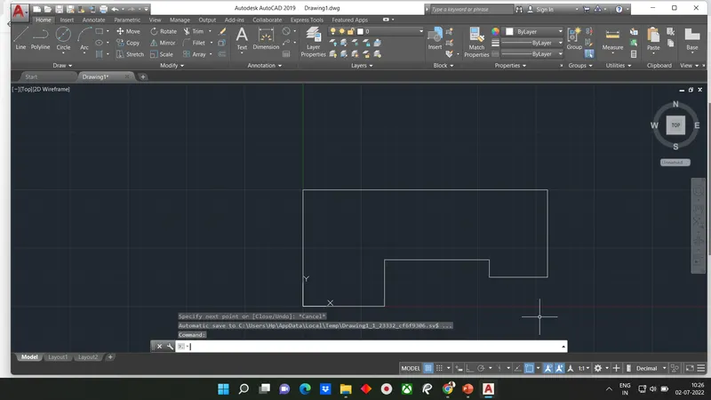
STEP-3
i)Click arc tool in ribbon
ii)Click Start, End Radius from the dropdown
iii)Click start and end point
iv)Enter 35 as radius
v)Click arc tool in ribbon
vi) Click start end ,radius from dropdown
vii)Enter 25 as radius
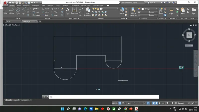
STEP-4:
i) Click circle Diameter in ribbon
ii) Enter 35,0 as centre
iii)Enter 50 as diameter
iv)Click circle Diameter in ribbon
v)Enter 185,25 as centre
vi)Enter 30 as diameter
vii)Delete two unconnected lines
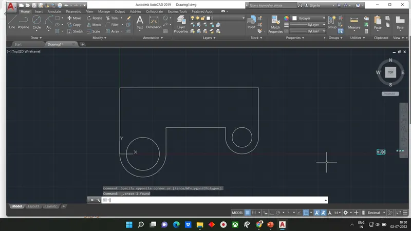
STEP-5:
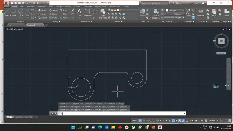
i)Enter F and select radius
ii)Enter 20 as fillet radius
iii)Select 1st object and 2nd object
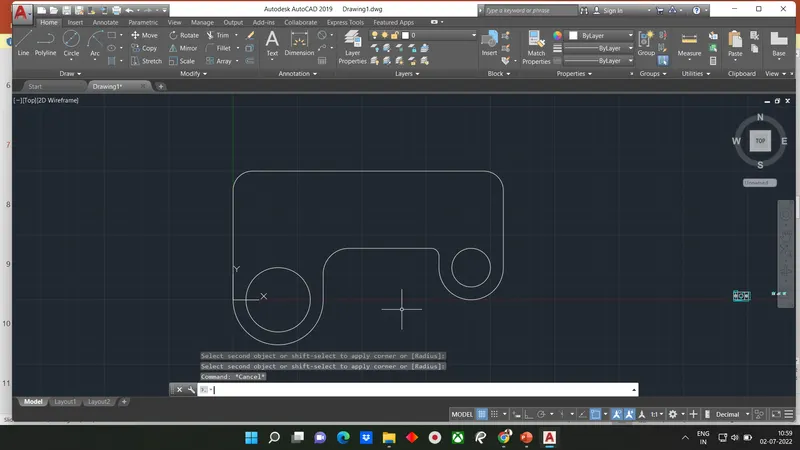
iv)Enter F and select radius
v)Enter 6 as Fillet Radius
vi)Select 1st object and 2nd object
vii)Enter F and select radius
viii)enter 15 as fillet radius
ix)Select 1st object and 2nd object
STEP-6:
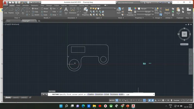
i)Enter REC
ii)Enter 20,90 as first corner point
iii)Click Dimension
iv)Enter 70 as length and 30as width
v)Enter 90,60 as another corner point
vi)Enter REC
vii)Enter 120,90 as first corner point
viii)Click Dimension
ix)Enter 70 as length and 30as width
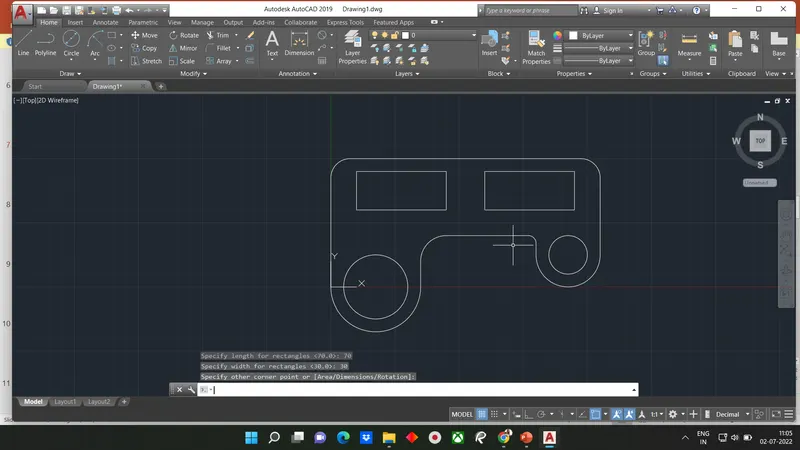
RESULT:

DRAWING-8
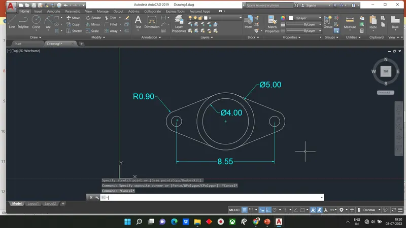
Aim: To create the geometry 8 using AUTOCAD
Introduction:The geometry of 8 drawing units using AUTOCAD is created by lines,arcs, circles and object snapping.The procedure and results should be written after creating geometry 8
Procedure:
STEP-1:
i) Open the AUTOCAD software and click start drawing tab
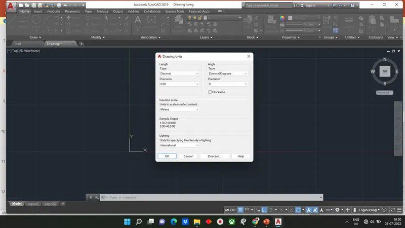
ii)Enter UNITS in command box
iii)Select DECIMAL in type 0.00 in Precision and meter in UNITS Press ok
STEP-2:
i)Select the line tool by entering LINE command in command tab
ii)Specify the first point as 5,5 in command line
iii)Specify the coordinate of next point as @8.55,0 in command line
iv)Press ESC
v)Select circle toold by entering Circle command line in command tab
vi)Specify the centre point of circle as mid point of line drawn previously
vi)Select the diameter option in command line
viii)Select the diameter of circle as 5
ix)Select the offset tool by entering offset command in the command tab
x)Enter 0.5 as offset distance in command line
xi)Select the circle of diameter 5 unit
xii)Click on inside of the circle
xiii)Press ESC
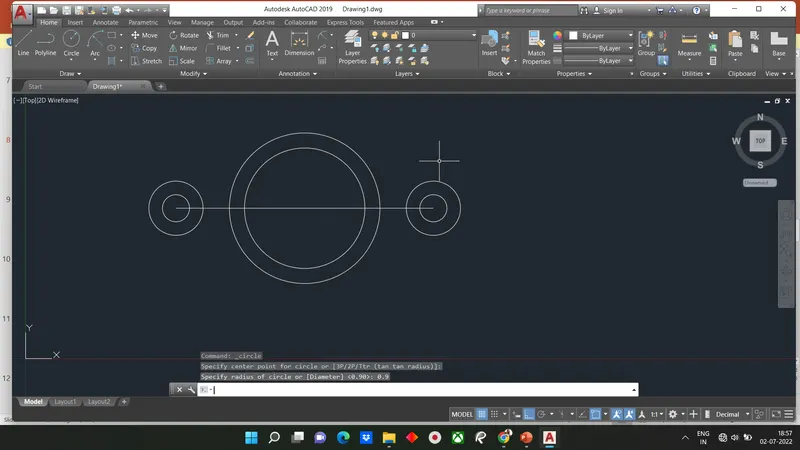
STEP-3:
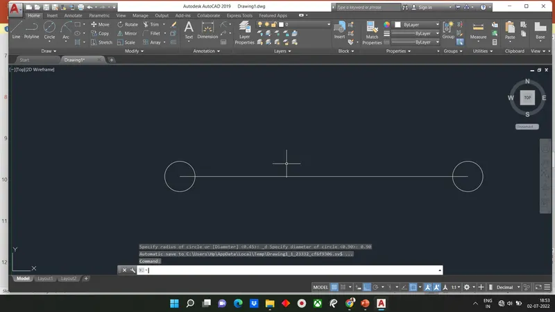
i)Select the circle tool by entering CIRCLE command in commamd tab
ii)Specify the centre point of circle as the start point of the line length 8.55 unit created in above drawing
iii)Select the diameter option in command line
iv)Specify diameter of circle as 0.90
v)Select the circle tool again by entering CIRCLE command in command tab
vi)Specify the centre point of circle as the end point of the line of length 8.55 units created in the previous step
vii) Select the diameter option in command line
viii)Specify diameter ofcircleas 0.90
STEP-4:
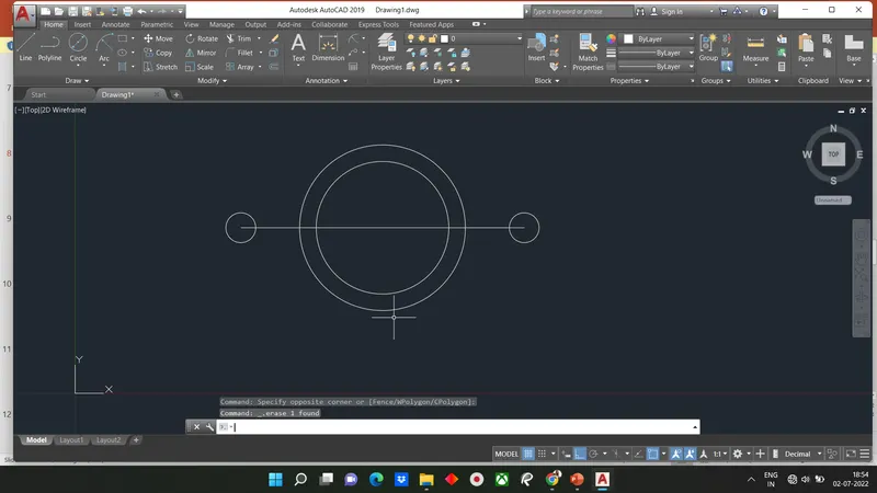
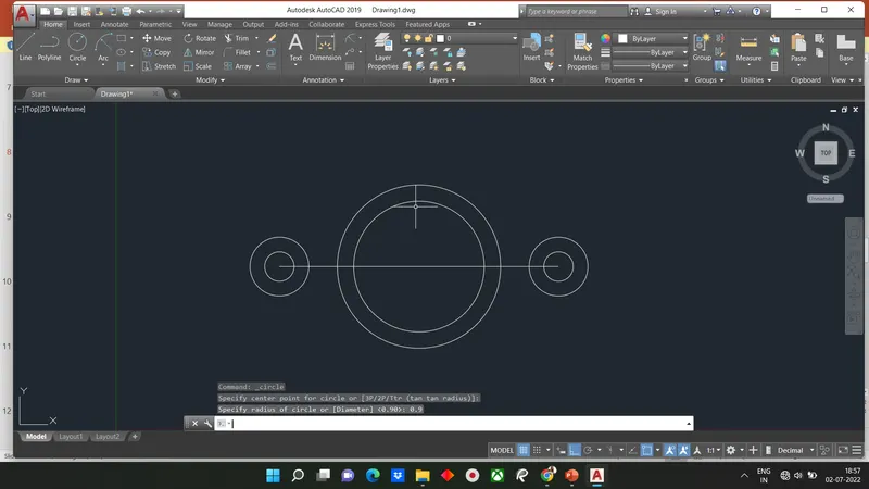
i)Select the circle tool by entering CIRCLE command in cimmand tab
ii)Specify the centre point of circle as the start point of the start point of the line of length 8.55 units created in step 2
iii)Specify radius of circle as 0.90
iv) Select the circle tool again by entering CIRCLE command in command tab
v)Specify the centre point of circle as the end point of the line of length 8.55 units Created in step 2
vi)Specify radius of circle as 0.90
STEP-5:
i)Enter OSNAP in command line
ii)In the drafting setting dialog box, unde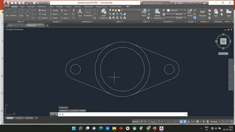 r object snap option, deselect all the snap modes and turn on only the tangent mode.
iii)Select the line tool by entering LINE command in command tab
iv)Draw a line joining the tangent point of the circle of radius 0.90 on the right side and the circle of diameter 5
v)Press Esc to cancel the line tool
vi)Repeat the above procedure to draw all four tangents
vii)Press Esc to cancel the line tool
viii)Select the trim tool by entering TR command in command tab
ix)Press Enter
x)Select Edge option and click on NO extend
xi)Select the unwanted lines to be trimed
xii)Press Esc
STEP-6:
i)Enter DIMS in command box
ii)Click modify
iii)Click Symbols and Arrow Enter required size
iv)Click Text Height
v)Click ok
vi) Select standard in style,Click SET CURRENT.Click close
RESULT:
DRAWING-9
Aim: To create the geometry 9 using AUTOCAD
Introduction: The geometry 9 units Using AUTOCAD is created by lines.Circles and object snapping the procedure and result should be written after creating the geometry 9.
Procedure:
STEP-1:
i)Go to start menu select AUTOCAD 2022
ii)In the command line type in: STARUP(Enter)
iii)Enter new value of startup 1
iv)Go to application menu and select new
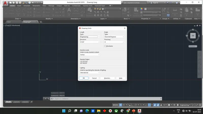
v)In the Create New Drawing Dialog Box, we do the advanced setup and select the engineering unit of measurement and select precision as '0'-0.0"
vi)Enter UNITS command in command tab
vii)In the drawing Units dialog box select Engineering in type '0-0.0"in precision and inches in insertion scale
viii)Click on Ok
STEP-2:
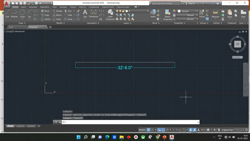
i)Select the line tool by entering LINE command in the command tab
ii)Specify the first point as 10',10' in command line
iii)Specify the coordinate of next point as in command line
iv)Press Esc to cancle line tool
v)Select the circle tool by entering CIRCLE command in command tab
vi)Specify the centre point of circle as the start point of the line of length 32'6" units created before.
vii)Specify radius of circle as 8'
viii)Specify the circle tool again by entering CIRCLE command in command tab
ix)Specify the centre point of circle as the end-point of the line of length 32'6"Units
x)Specify radius of circle as 9'
STEP-3:
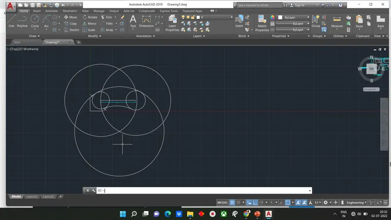
i)Select the circle tool by entering CIRCLE command in the command tab
ii)Specify the centre point of circle as the centre of the circle of radius 8' drawn in step2
iii)Specify radius of circle as 33'8"
iv)Select the circle tool again by entering CIRCLE command in command tab
v)Specify the centre point of circle at the centre of circle of radius 9' drawn in step 2
vi)Specify radius of circle as 32'8"
vii)Again select the circle tool again by entering CIRCLE command in the command tab
viii)Specify the centre of the circle tool again by entering CIRCLE command in the command tab
ix)Specify the radius of the circle as 41'8"
STEP-4:
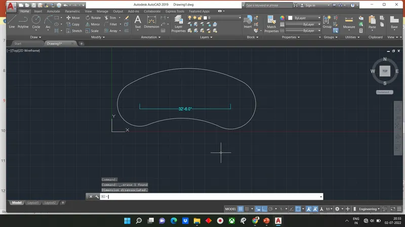
i)Select the circle tool by entering CIRCLE command in the command tab
ii)Select the 'tan tan radius' option in the command line
iii)Select the first tangent at bottom of left circle
iv)Specify the second tangent at the bottom of the right circle
v)Specify the radius of the circle as 20'10"
vi)Select the trim tool by entering TR command in command tab
vii)Press Enter
viii)Select Edge option and click on no extend
ix)Select the unwanted lines to be trimmed
x)Press Esc to cancel
RESULT:
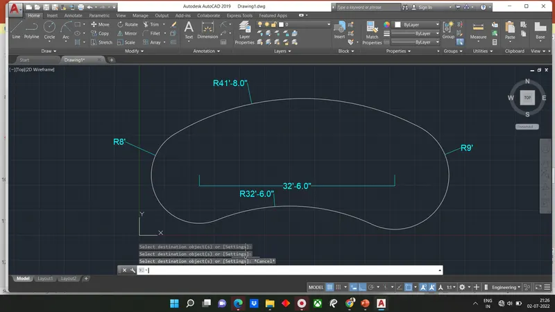
DRAWING-10:
Aim: To create geometry 10 using AUTOCAD
Introduction: The geometry 10 units using AUTOCAD is created by lines, arcs, circles and object snapping.The Procedure and result should be written after creating the geometry 10
Procedure:
STEP-1:
i) Open the AUTOCAD software and click start drawing tab
ii)Enter UNITS in command box
iii)Select DECIMAL in type 0.00 in Precision and meter in UNITS Press ok
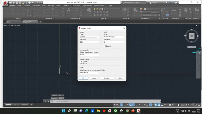
STEP-2:
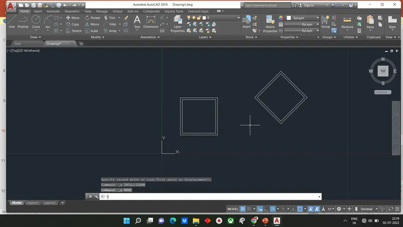
i)Select the rectangle tool by entering Rec command in the command tab
ii)Specify the first point as 5,5 in command line
iii)Select dimension option in the command line
iv)Specify length of rectangle as 10 in the command line
v)Specify width of rectangle as 10 in the command line
vi)Move the cursor towards the upward and click Enter
vii)Select the offset tool by entering offset command in the command line
viii)Enter 0.5 as offset distance in the command line
ix)Select the rectangle of size 10x10
x)Click on the inside of the rectangle
xi)Press Esc
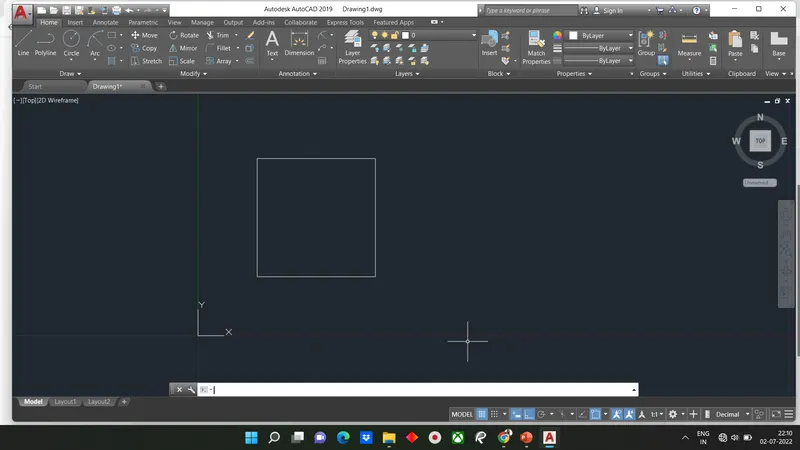
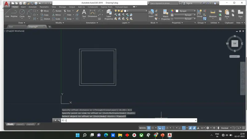
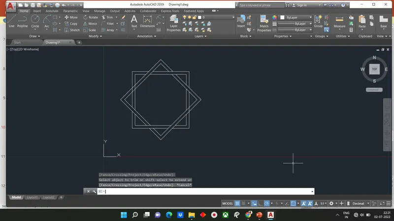
STEP-3:
i)Select the copy tool by entering copy command in the command tab
ii)Select the drawing created in step2
iii)Specify the base point and click enter
iv)Select the rotate tool by entering RO command in the command tab
v)Select the copied object and specify the base point
vi)Specify rotation angle as 45
vii)Select the move tool by entering M command in the Command tab
viii)Select the rotated object and specify the base point
ix)Move the object to the desired location(Keep ortho mode off)
x)Select the trim tool by entering TR command in the command tab
xi)Press Enter
xii)Select unwanted lines to be trimed
xiii) Press Esc
RESULT:
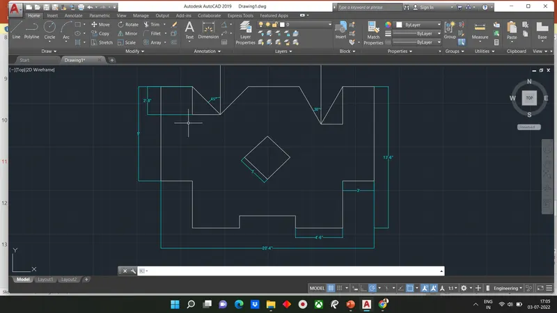
DRAWING-11:
Aim:To create the geometry 11 using AUTOCAD
Introduction:The geometry 11 units using AUTOCAD is created by lines.Circled and object snapping.The procedure and result should be written after creating geometry
Procedure:
STEP-1:
i)Go to START menu, Select AUTOCAD 2022
ii)In the command line type in: STARTUP (Enter)
iii)Enter new value of startup:1
iv)Go to application menu and select new
v)In the Create New Drawing Dialog Box, we do the advanced setup and select the engineering unit of measurement and select precision as 0'-0.0"
vi)Enter UNITS command in the command tab
vii)In the drawing units dialog box, selecy Engineering in type 0'-0.0" in precision ad inchesin insertion scale
viii)Click on ok
STEP-2:
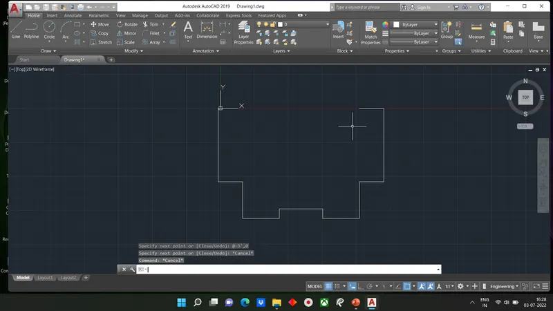
i)Select the line tool by entering LINE command in the command tab(keep ortho mode on)
ii)Specify the first point as 0,0 in th command line(point a_
iii)Specifythe coordinate of next point as @-3,0 in command line
iv)Specify the coordinate of next point as @0,-9 in the command line
v)Specify the coordinate of next point as @3,0 in command line
vi)Specify the coordinate of next point as @0,-4'6" in the command line
vii)Specify the coordinate of next point as @4'6",0in command line
viii)Specify the coordinate of next point as @0,1'2" in command line
ix)Specify the coordinate of next point as @5'4",0 in command line
x)Specify the coordinate of next point as @0,-1'2" in command line
xi)Specify the coordinate of next point as @4'6",0 in command line
xii)Specify the coordinate of next point as @0,4'6" in command line
xiii)specify the coordinate of next point as @3,0 in command line
xiv)Specify the coordinate of next point as @0,9 in command line
xv)Specify the coordinate of next point as @-3,0 in command line(point b)
xvi)Press Esc
STEP-3:
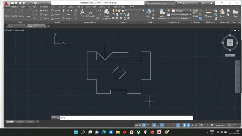
i)Turn ortho off and click on polar tracking from the status bar and select 30,60,90... from the drop down list
ii)Select the line tool by entering LINE command in command tab
iii) Specify the first point at b, then pointing the cursor downward enter a length of 3'7"
iv)Next, pointing the cursor towards left draw a line of any arbitary length of over 2
v)Press Esc
vi)Select the mirror tool by entering MIRROR command in the command tab.
vii)Select the objects to mirror (ie the line drawn just before) and click Enter.
viii)Select first point mirror line
ix)Select second point of mirror line
x)Click No in erase source object 1?prompt
xi)Again click on the polar tracking from the status bar and select 45,90,135...From the dropdown list.
xii)Select the line tool by entering LINE command in command tab
xiii)Specify the first point at a, then pointing the cursor downward enter a length of 2'8".
xiv)Next, pointing the cursor towards left draw a line of any arbitary length of over 3'
xv)Press esc
xvi)Select the mirror tool by entering MIRROR command in command tab
xvii)Select the object to mirror(ie the line drawn just before)and click enter.
xviii)Select first point of mirror line
xix)select second point of mirror line
xx)Click no in Erase Source Object? Prompt
xxi)Select the line tool and join the two open ends of the drawing
xxii)Press Esc to cancel
xxiii)Again select the line tool and draw bisecting both the angles
xxiv)Press esc
STEP-4:
i)Trim and erase the unwanted lines in the drawing
ii)Select the line tool and draw a line from the midpointof base line, such that it divides the geometry into two halves
iii)Press esc
iv)select the rectangle tool by entering Rec Command in command tab
v)Specify the first point as 7'2',-9' (i.e coordinates from point a) in the command line
vi)Seleict dimensions option in the command line
vii)Specify length & width of rectangle as 3' in command line
viii)Move the cursor towards the upward and click Enter
ix)Select the rotate tool by entering RO command in command tab
x)select the rec of size 3',3'and specify the base point at the bottom left corner of the rectangle.
xi)Using polar tracking rotate the rectangle to an angle 45 about the middle line
RESULT: