Creating a Floor plan, Footing detail and Isometric view using AutoCad
DIAGRAM 1:Cross-section of load bearing wall over spread footing
AIM: To create a cross-section of load bearing wall over spread footing using AutoCAD.
Introduction: The cross-section of load bearing wall over spread footing using autoCAD is created by lines and rectangle command. The procedure and result are written after creating the cross-section of the load bearing wall over spread footing using autoCAD.
Command Used:
Line
Rectangle
Trim(TR Double Enter)
Procedure:
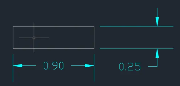
Step-1: Create rectangle by typing "REC" in command box
- Specify first corner point as (5,5)
- Specify Length of rectangle 0.9
- Specify Width of rectangle 0.25
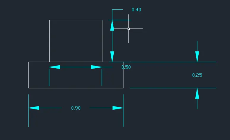
Step-2: Create another rectangle "REC"
- Specify first corner point as 0.2 from starting point of first rectangle
- Specify length of rectangle as 0.5 and width of rectangle as 0.4
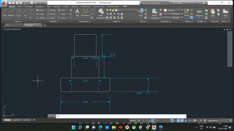
Step-3: Create 3rd reactangle
- Specify first corner which is 0.05 units from starting point of second rectangle
- Enter length of rectangle 0.4 and width of rectangle as 0.4
Step-4: Line(command L) is drawn from corner of third rectangle
- Give length as 1.15unit
- Move cursor downward and give value 0.15 unit & Right give 1.15 unit
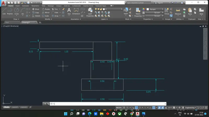
Step-5: Fourth rectangle is drawn by Command Rec
- Specify 1st corner point at a distance of 0.05 from 3rd rectangle
- Give length as 0.3 & width as 0.6
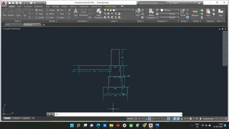
Step-6: From line draw step in 4, at a distance of 0.3, draw another line with distance of 0.15 units vertically & 0.3 units horizontally
- Continue it 2 more time, untill 3 more steps are created.
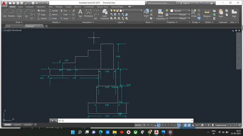
Step-7: Draw another rectangle above 4th rectangle Command REC
- Specify corner point as corner of fourth rectangle
- Give length as 0.3 and width as 0.05
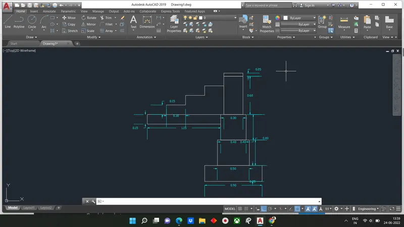
Step-8: Draw 5th rectangle by command REC
- Specify corner point as corner of fourth rectangle
- Give dimension length as 0.3 unit width as 1 unit
- Erase unwanted line by Trim
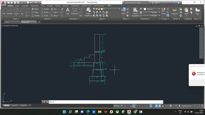
Result
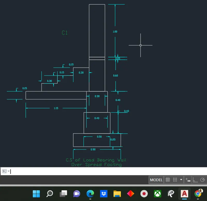
DIAGRAM-2 : C.S Isolated Footing
AIM: To Create a Cross-Section of Isolated Footing
Introduction: The Cross-Section of the isolated footing using AUTOCAD is created by lines and rectangle command.The Procedure is written and results are written after creating the cross-section of a the isolated footing using.
Command Used:
Line (L)
Offset (O)
Trim (Tr Double Enter)
Mirror (Mi)
Procedure:
Step-1: Draw a line with command "L" and give 1 unit
- Give command "L" and give the relative coordinate as @0,0.15
- Give next coordinate as @0.38,0.25
- Next coordinate is given as @0,1.6
- Give @0.28,0
- Next coordinate @0,-1.6
- Next coordinate @0.38,-0.25
- Next @0,-015 or Close
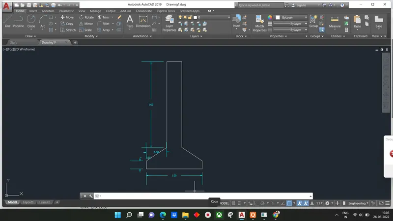
Step-2: Draw an offset with the command at a distance of 0.04 from the bottom line to up wards
- Give command of "o" and select the object and give offset distance as 0.04
- Do the same at right and left bottom end
- Trim unwanted lines
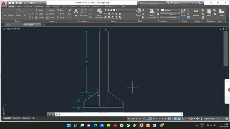
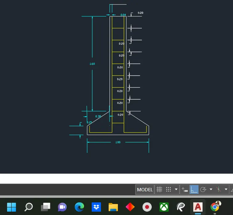
Step-3: Give offset from the top line with an offset distance of 0.2 units.
- Give command "o" an select object
- Give the oofset distance as 0.2
- Select multiple option a 9 such lines
- Trim excess lines
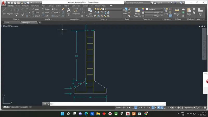
Result: Cross-section of Isolated footing is drawn
C3 Line Diagram of 2 Bedroom building
Aim: To draw Line diagram of 2 bedroom building
Introduction: The line diagram of 2 bedroom building using autocad is created by lines and rectangle command. The procedure is written and results are written after creating line diagram of 2 bedroom building using AutoCAD.
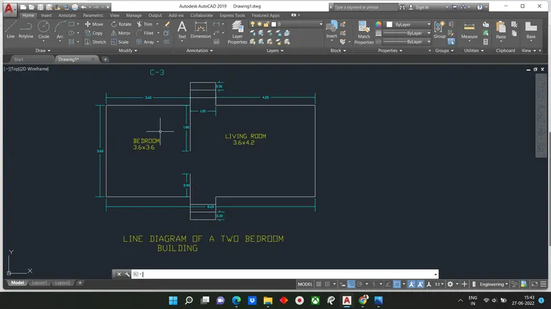
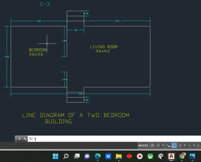
Line Drawing are drawing with detailsof dimensions and component of building.The 2 bedroom consist of 1 -Living room & 1- Bedroom and stairs in both direction.
Command Used:
Line
Offset
Rectangle
Trim
Procedure:
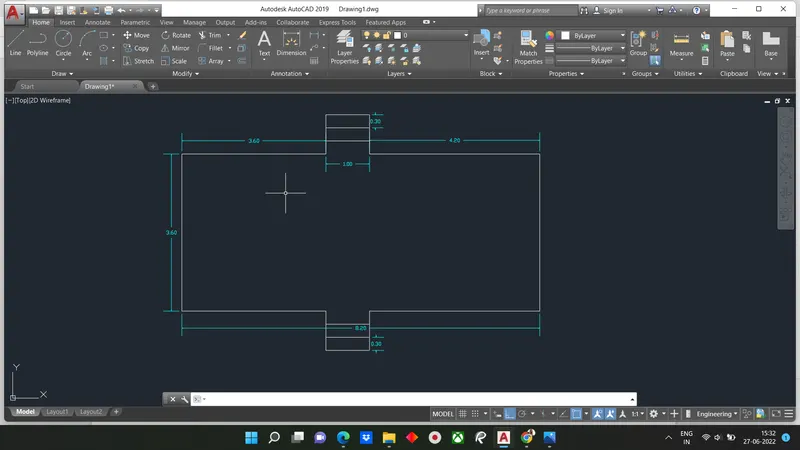
Step-1: Creating Bedroom (8.2x3.6) by rectangle
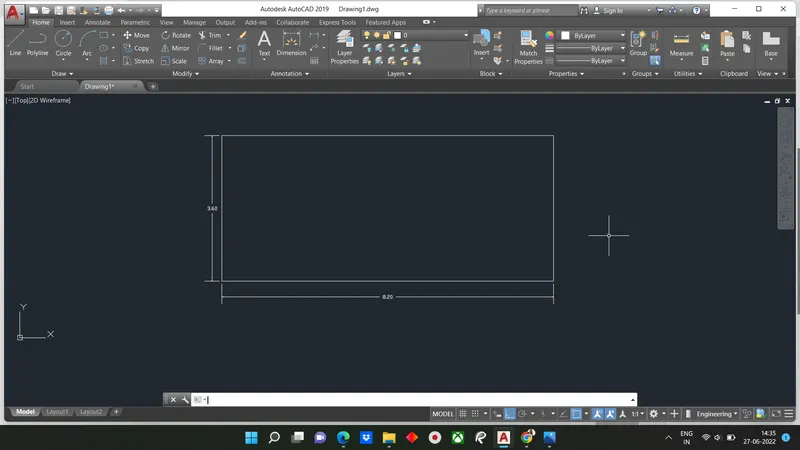
Step-2: Use command "explode" and select the rectangle
- Draw an off set using the command "o"
- In the command line enter "o" and specify the distance of 3.6 units from left bottom end
- Draw an offset using the command "o" at a distance of 4.2unit from right bottom end
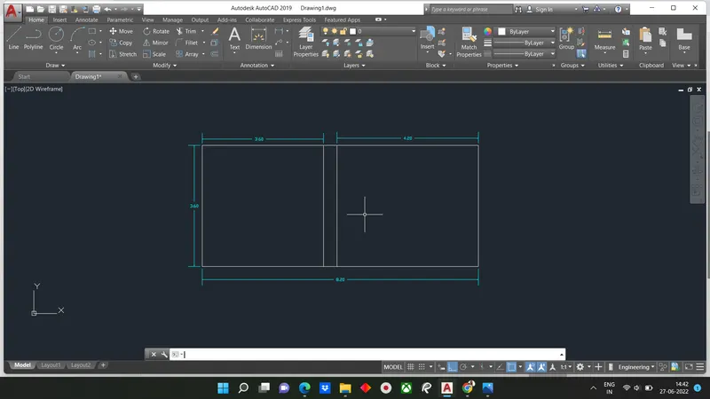
Step-3: EXtend the two line in the bottom and in the top
- Draw an off set at a distance of 0.3 between the two line to bottom side
- Repeat the same step and create two offsets
- Do the same process in the top
- Trim the unwanted lines
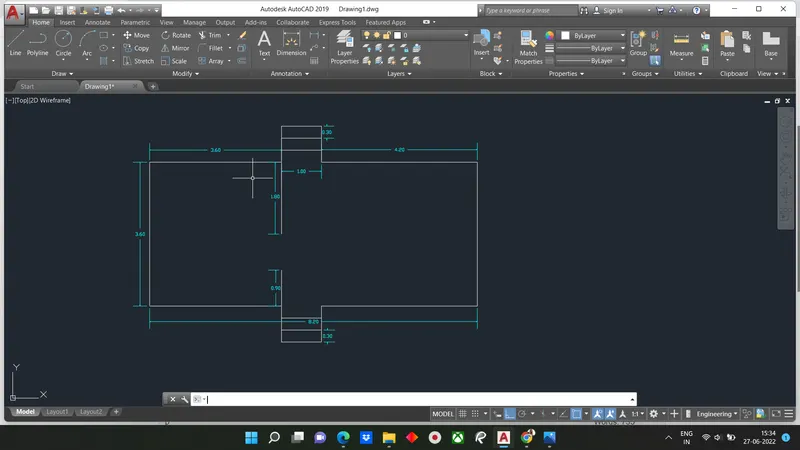
Step-4:
- Using Line commande draw a line at a distance of 3.2units from left bottom end to up wards 0.9 units
- Using line command draw a line at a distance of 3.2 units from the left top end to downward 1.8 units
RESULT:
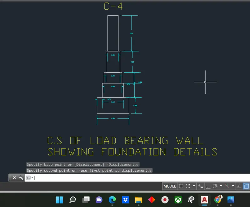
C-4: Cross-section of load bearing wall showing foundation details
Aim: To draw cross-section of load bearing wall showing foundation details
Introduction: Cross-section of load bearing wall showing foundation using AutocCAD is created by lines and rectangle command. The procedure and result are written after creating c/s of load bearing wall showing foundation.
This type of foundation or load bearing wall is a wall that takes loads column, beams and slab & transfer load coming from those to ground below.
Command Used:
Line
Rectangle
Trim
Procedure:
Step-1 -Create rectangle by typing REC in command box
- Specify first corner point as(5,5)
- Specify length of rectangle -0.9 units in command box
- Specify width of rectangle -0.45 unit in command box
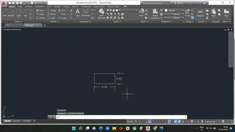
Step-2 -Create another rectangle REC in command box
- Specify first corner point which is 0.15 units from starting point of second rectangle
- Enter length of rectangle as 0.6 unit the width of rectangle as 0.4 unit
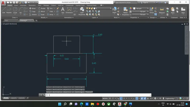
Step-3 -Create 3rd recatngle REC
- Specify first corner point which is 0.05 unit from starting point of second rectangle
- Enter length of rectangle as 0.5 unit width of rectangle as 0.3 units.
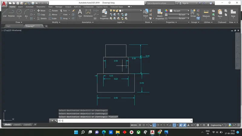
Step-4 -Create 4th rectangle command REC
- Specify first corner point which is 0.05 units from the starting point of second rectangle
- Enter the length of rectangle as 0.4 units the width of rectangle as 0.6 unit
Step-5 -Drawn the fifth rectangle command REC
- Specify the corner point as corner of fourth rectangular
- Click on dimension give length as 0.3 units abd width as 1 unit
- Erase the unwanted line by trim
RESULT:
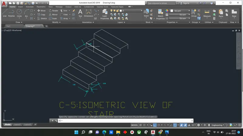
C-5: ISOMETRIC VIEW OF STEP
Aim: To draw isometric view of step
Introduction: Isometric view of staircase using AUTOCAD is created by lines and rectangle command.The procedure and result are written after creating the isometric view of step.
Stairs are important component of building which used to join different floor at different heights, stairs have 2 component 1 vertical known as rise and 1 horizontal known as thread to run
Command Used:
Line
Isometric Plane
Trim
Procedure:
1. To work with isometric view command "ds" snap off, grid off put isometricsnap on
2. Make sure that ortho mode is on
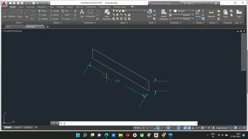
Step-1: From isometric drafting select iso plane left
- Give command L and moving cursor to x direction(left) and give unit 1
- Moving cursor to +y direction(top ) give 0.15 units
- Moving cursor to +x direction again give1 unit and cursor to y direction(downward) give 0.15 unit
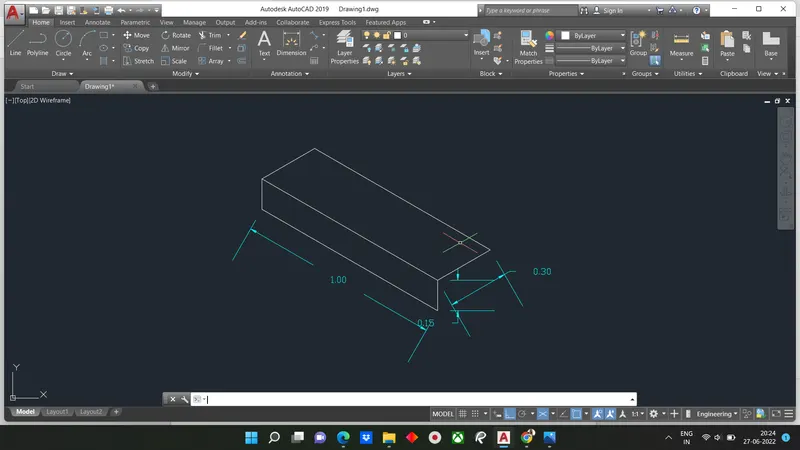
Step-2: Change the isometric drafting to iso plane top
- Move cursor to back and give 0.3units fromthe last drawn point
- Move the cursor to right direction and give 1 unit
- Move the cursor to front give 0.3 unit
Step-3: Change the isometric drafting to iso-plane right
- Copy The object drawn ortho off
- Command "co" and specify the base point and place it to new point
- Repeat it until 4 steps are formed
Step-4: With isoplane right join two ends with ortho off
Result: The steps are drawn in isometric view
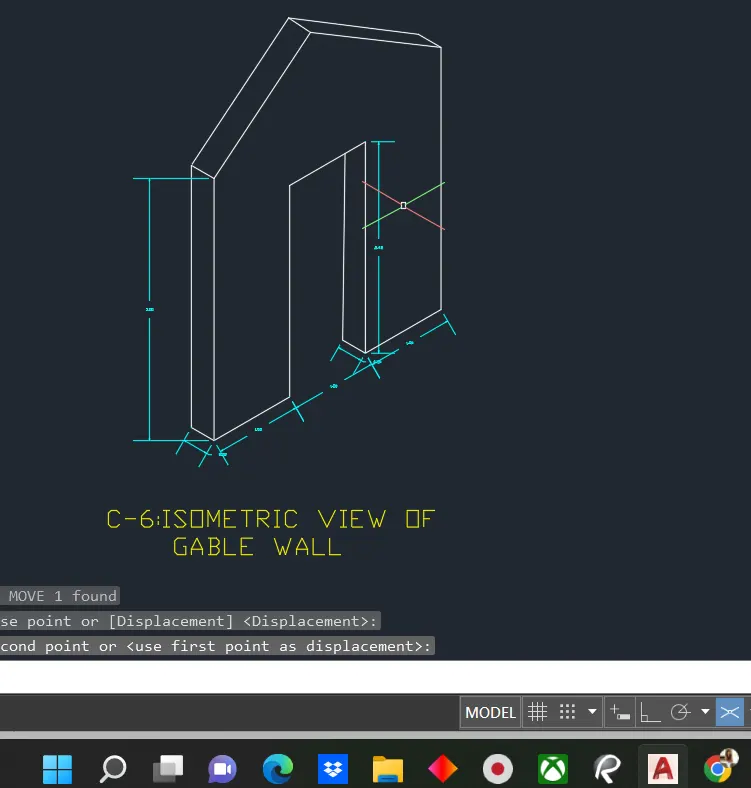
C-6: Draw a Isometric tube of Gable Wall
Aim: Draw an isometric view of gable wall
Introduction: The isomteric view of goble wall using AUtocad is created by lines and rectangle command. The procedure and result are written after creating isometric view of gable wall using AUTOCAD
Command Used:
Line
Isometric Plane
Procedure:
Step-1: From isometric drafting select isoplane left
- Give command L and moving the cursor to right give 1 unit
- Pointing the cursor upward give 3 unit
- Draw 0.3 units to left and 3 units downward and 0.3 units to left
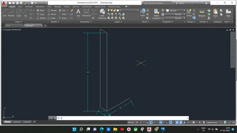
Step-2: Using isometric right take line command and drawline upward of 2.42 unit from the starting point of step 1
- Draw 1 unit towards right and 2.42 unit downward
- using isometric left again using line command draw 0.3 unit to left side and draq a line whichintersects the top line
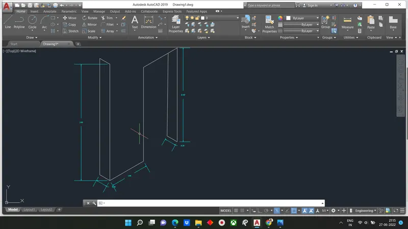
Ste
p-3: Using Isometric right with the line command draw1 unit to right Side and 3 units upwards.
Step-4: By Usingthe line command draw a line bottom left corner @1.5 units and extend line 4 units upwards i.e total 3.25 units from bottom
Step-5: With ortho off draw a line between the corner of left side and projected line done in step 4
- Draw it to other side also till it meetsthe right corner
Step-6: Draw the vertically line with ortho on @0.3 and join the vertical line using from left and right end same as in step 5 remove unwanted lines by using erase.
Result: