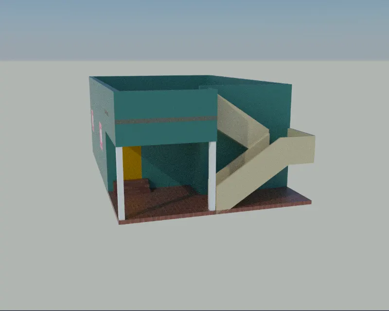
Project 2_Creating a 3D rendered model for a Residential Building in AutoCad
Create a 3 dimensional model of the residential building with a rendered view.
Aim:
To create a 3 dimensional model of the residential building with a rendered view by using the Revit software
Introduction:
Create a 3 dimensional model of the residential building with a rendered view
Procedure:
- First star the model drawing with using the Drafting & Annotation workspace in the AutoCAD software
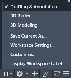
- Here, I want to draw the residential building plan in the units
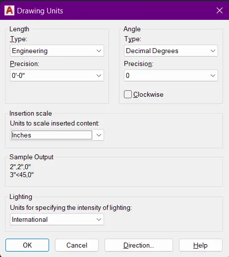
- Uisng the UN command for Units
- Length type is Engineering, Precision is 0'-0" and the Insertion scale is Inches
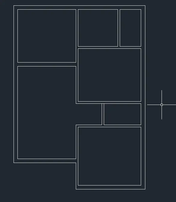
- And draw the plan view of the residential building by using the command of Line in the flat size of 25' x 45'
- By using the Offset command for give a wall thickness of the building. The thickness of the wall is 9" and 5"
- Using the Chamfer command for join the all corners in the drawing
- And using the Join command for join the all the lines inbetween the gapes
- The plan of the building is as shown in below figure
- Then take the dimension lines in the plan vertical and horizontal distance of the building
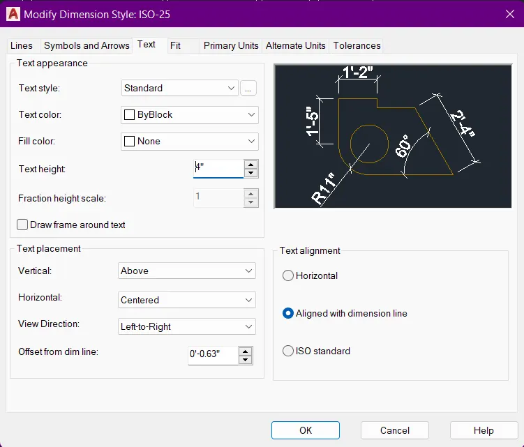
- Here using the Dimstyle command for create the Dimensions as I want
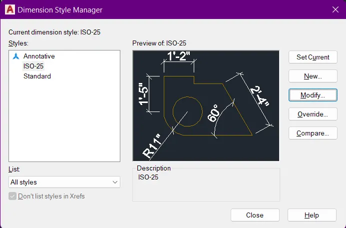
- And edit the option in the dimstyle dialogue box
- First select the Modify option for edit the sub options what I want
- Click lines option then give the offset from origin is 2"
- Then select the symbols and arrows option and give the arrowhead is Oblique
- And select the Text option and give the text height is 4"
- Finally I select the Primary units option and give the Length type is Engineering, Precision is 0'-0" and the Insertion scale is Inches
- The Dimstyle is finalised and click OK button and select Setcurrent option then click the Close button
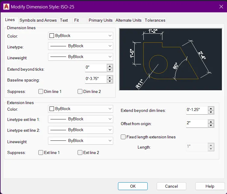
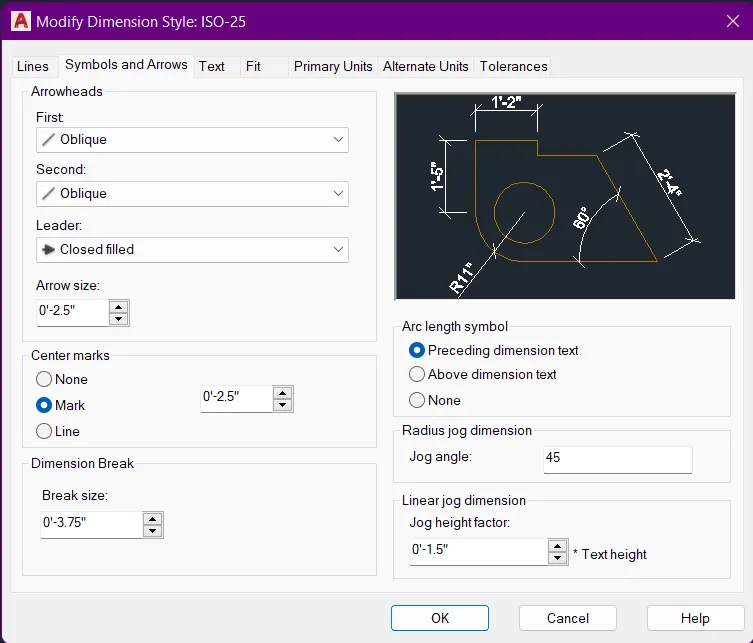
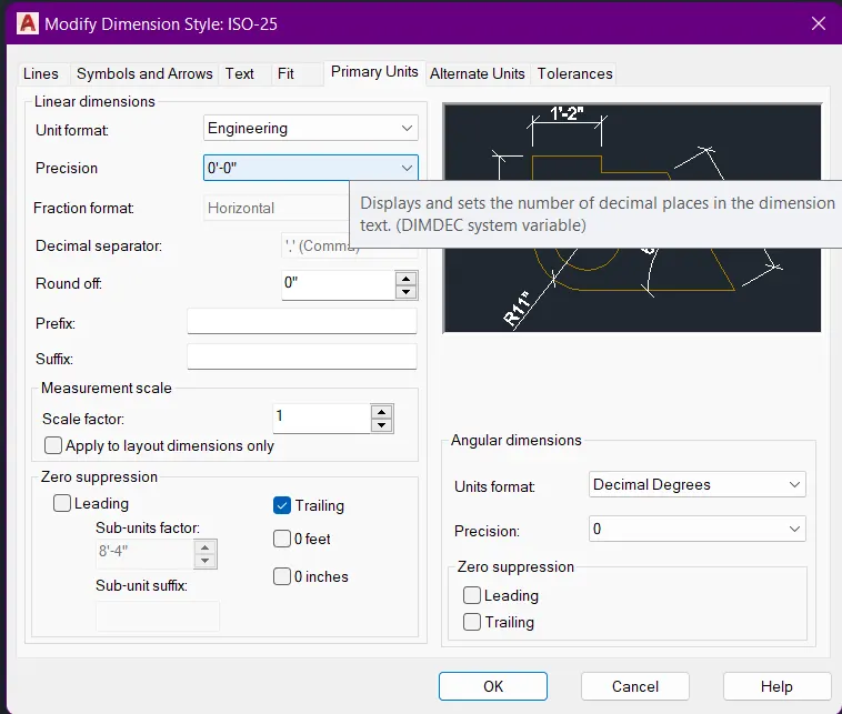
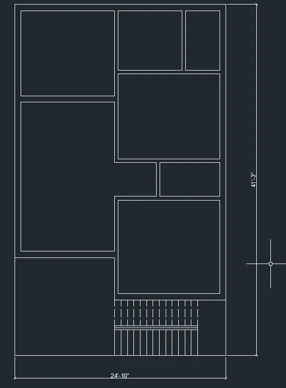
- Here, using the Dimlinear option for take the dimension of the building plan
- And draw the Staircase by using the Line command and give a dotterline for upward direction second flight of the staircase
- Here, I am used the staircase is Doglegged staircase
- And then give a layer for the all lines by using the Layer properties option in the Home toolbar
- Then take the new layers for the individual components in the plan as my wish
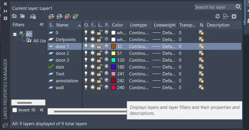
- Here, I am given the layers to the building plan for the identifications of the line layers
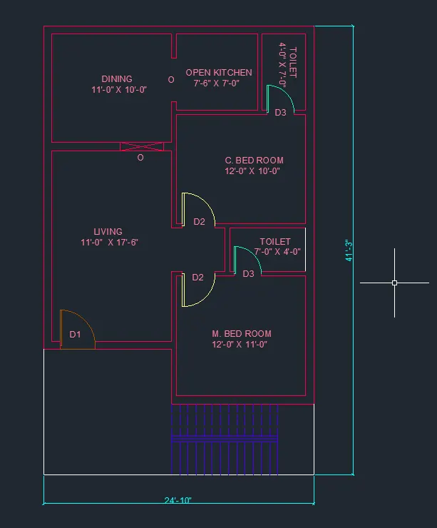
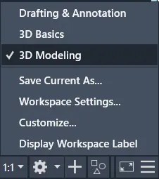
- After that I am move to the 3D Modeling workspace for create the 3D model of the building by using the Setting toolbar
- And here I am created the windows in plan by using the Line command
- Then click the 3D View cube in the workspace

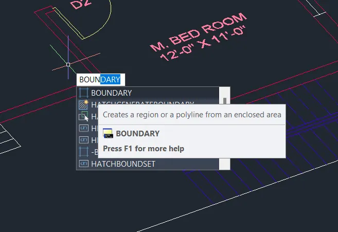
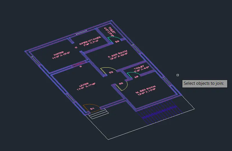
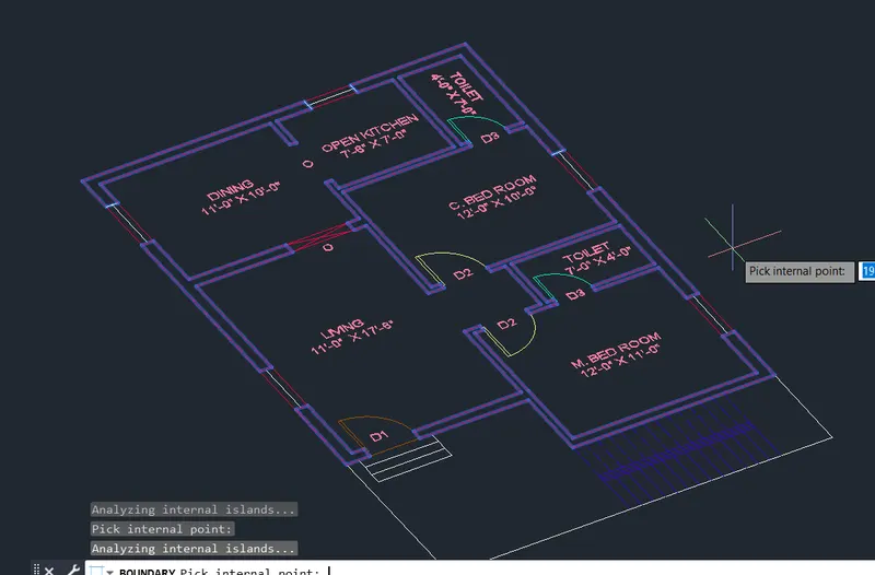
- Create the boundary for extrude the walls in 3D view using the Boundary command
- Ans select the all wall areas
- Then finalise the the boundaries in the building plan
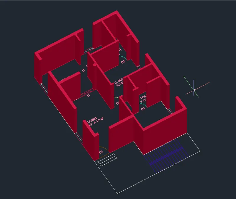
- The boundaries are as shown in below figures
- And here Extrude the walls using the Extrude command the height of 10' from the floor area
- The height of the basement is 2'
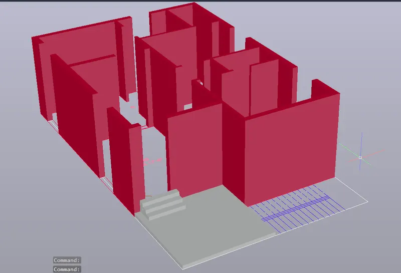
- And create the steps and parking area by using the Extrude command
- The parking area height is 6" from the GL
- The below figure is shows the steps and the parking areas
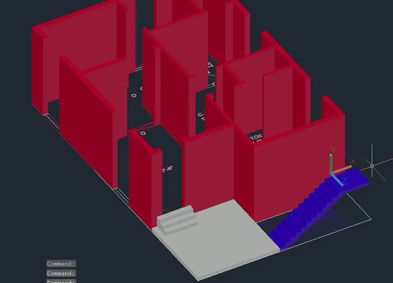
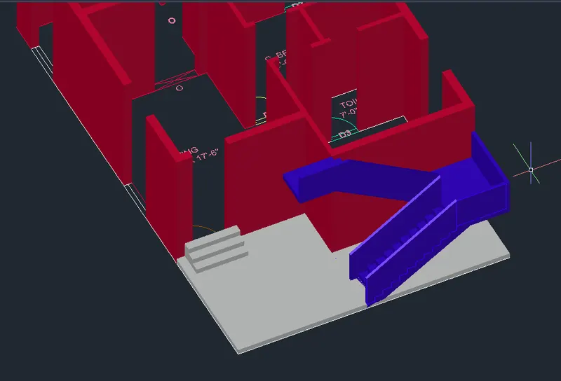
- Next I am ceated the steps using the Line command and UCS command for draw the side elevation of the staircase
- In UCS command I am selec the Face option and select the face
- After created the side elevation drawing using the Extrude command then extrude the stair in 3'-3" width
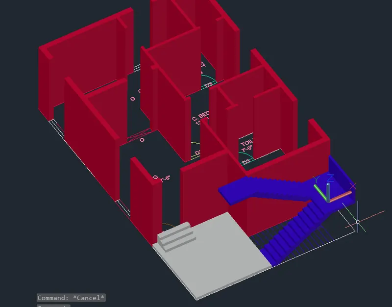
- And create the seconf flight of the stair is copy the extruded portion and mirror it and drag to move the portion
- And then fix the position where I want
- Then create the landing also the above given commands
- Then create the above form lintel level wall by using the UCS command and select the Face option
- Then draw the Rectangle in that position by using REC command
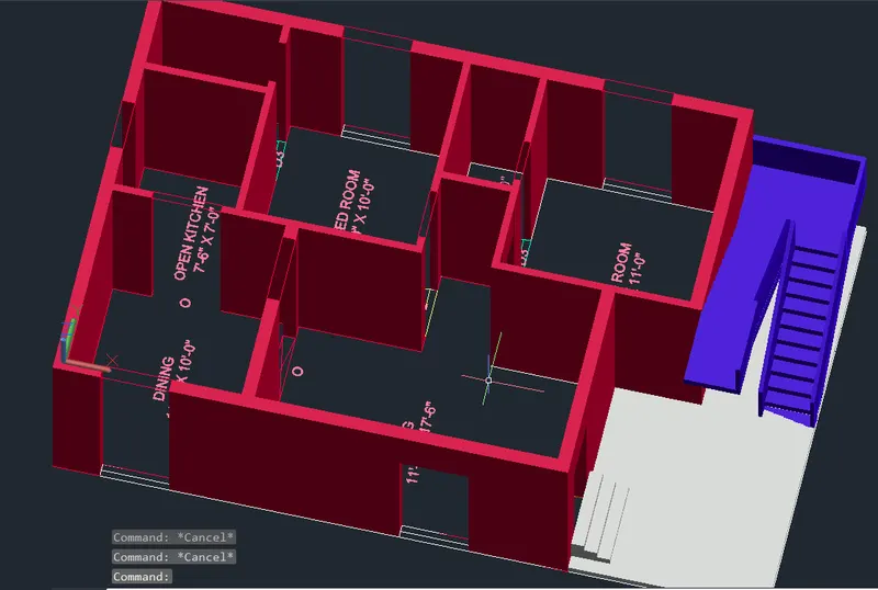
- Finally create all walls, window openings and wall openings
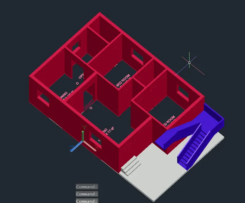
- And then create floor area by using the PLine command for create the floor area inside the wall
- Then using the Extrude command drag the floor in 2' from the actual drawn level
- And give the door colors as given in the plan
- The below figure shows the doors and floor area drawn
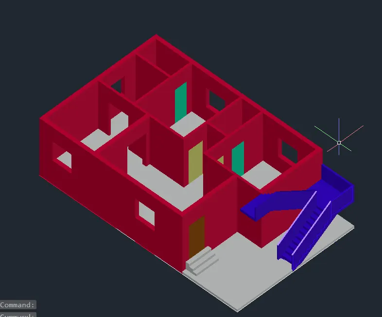
- Then create the roof by using the PLine and Extrude command
- And make finishes in the roof area
- Draw the Column area in the corner of the roof area and drag to extrude the column roof to parking area floor
- As shown in the below figures
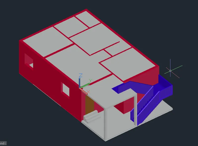
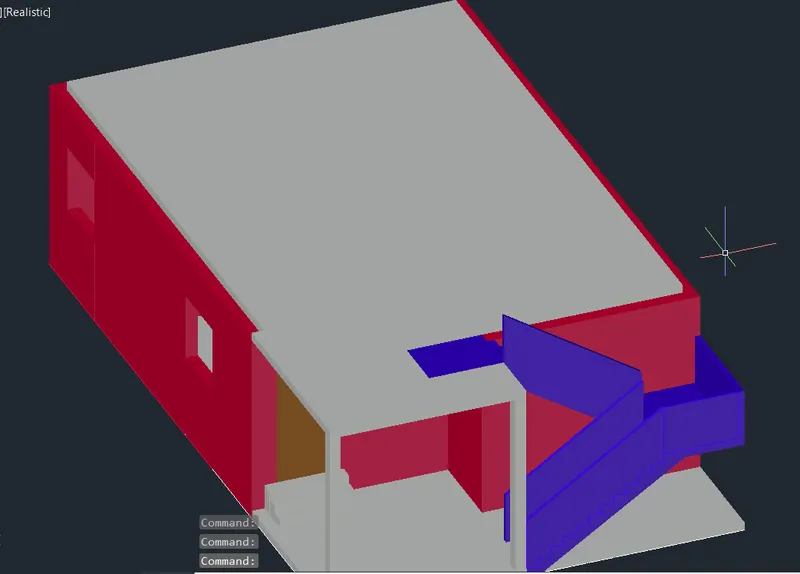
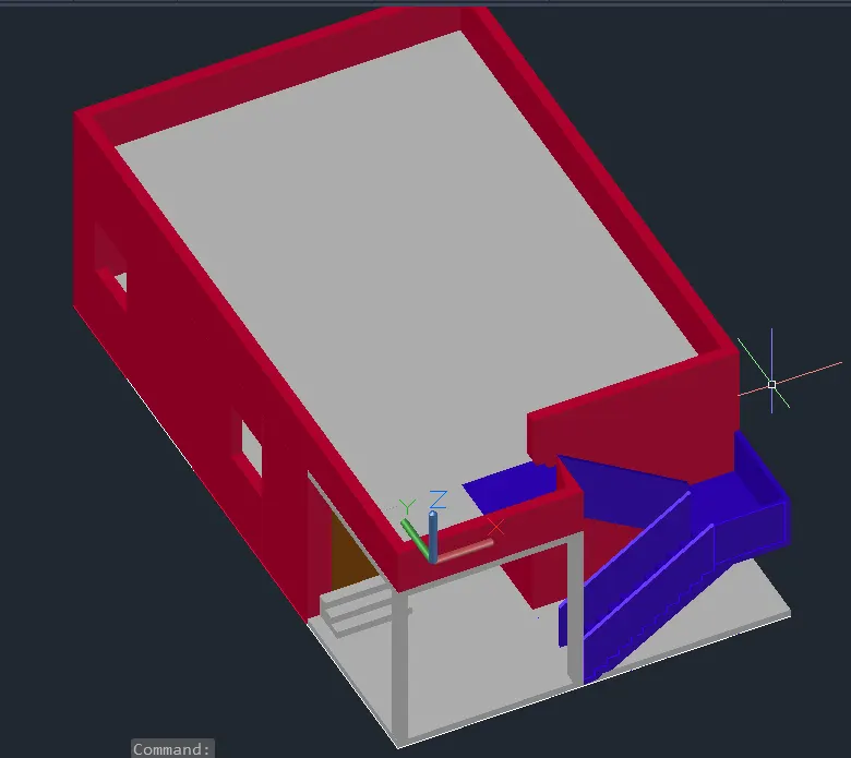
- And here, create the Parapet wall by here also the PLine and Extrude commands for creating the wall height of 3'
- Finally the creation of 3D view of the building is created using the ablove given process
- The below figures shows the 3D view of the buinding
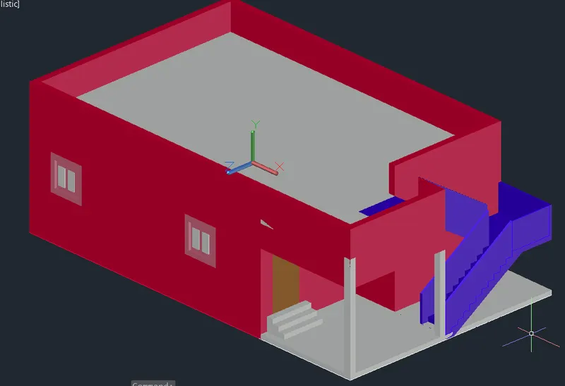
- Here create the window as I want
- using the Extrude, Rectangle and UCS commands for create a window and copy the wondow to the next one
- The final process of the creation is material apply in the model
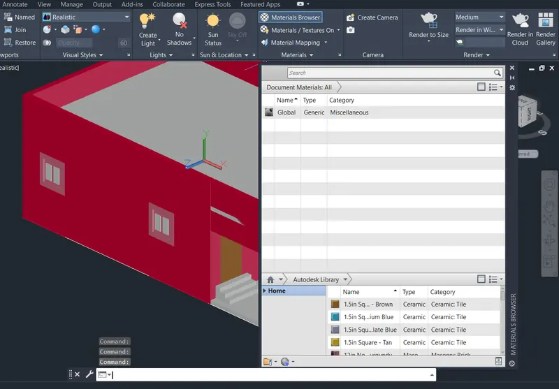
- By using the Materials Browser option in the Visualize toolbar tab
- After select the Browser the Materials browser dialogue box is open
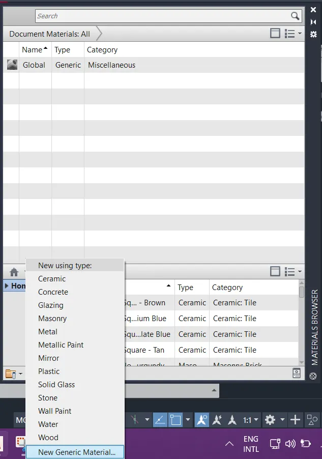
- And Add a New generic material
- Then select the Material which one is I want to give the building
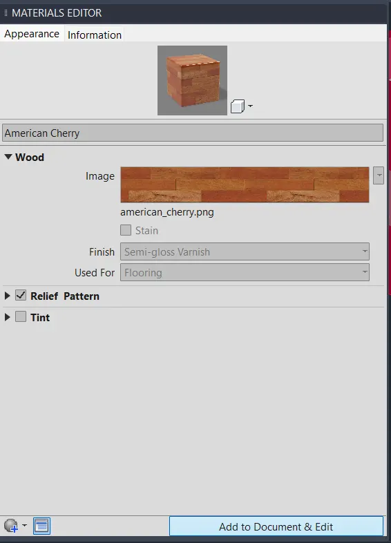
- After click this option the Material editor dialogue box will appear
- Finally click the Add to Document & Edit option in the Material editor dialogue box
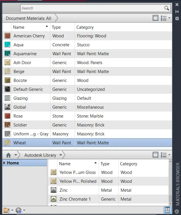
- And select the materials which one is want to provide in the building components
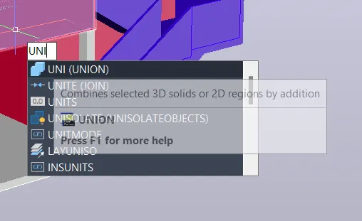
- Using the Union command to connect all the extruded components in the building created
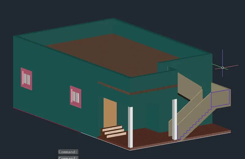
- After finish this process apply the materials to the building created
- The finished building is appear as given in below figure
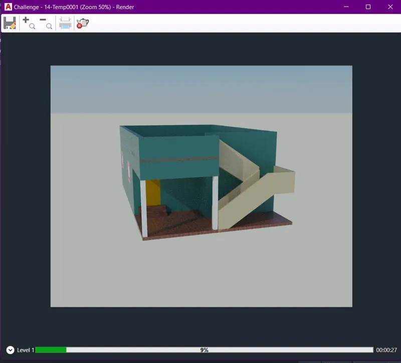
- And Render the building by using the Render (RR) command
- Here select the Sun status and Sky backround and illumination option in the Visualize toolbar
- Select the render quality is High
- And render the view
- The below figure shows the rendering progress of the 3D model

Result:
The creation of a 3 dimensional model of the residential building with a rendered view by using the Revit software is created successfully