Creating a Floor plan, Footing detail and Isometric view using AutoCad
Aim:
To creating a floor plan, footing details and isometric view of the given drawings using AutoCAD software as shown in the result
Introduction:
- The drawing is given in the attachment
- Use the AutoCAD 2023 software
- Refer the dimesions as in the drawings and draw the sketches
- Procedure of how to draw the drawing is given below
- Take the screenshot using the snipping tool
Procedure:
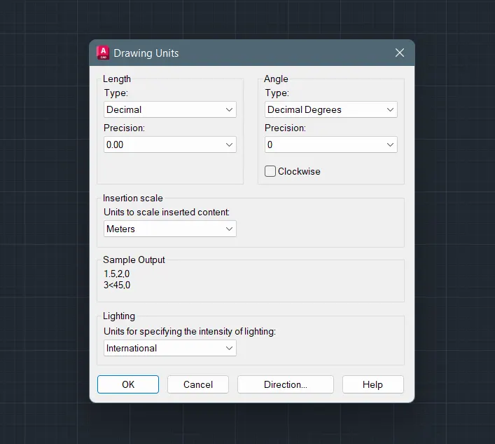
Step-1: Open the AutoCAD software and set the units and limits
- First open the software and type the shortcut of units (UN)
- The limit is using 5000,5000 and enter the Zoom (Z) enter and then, All (A) enter
- And set the decimal, meter and decimal degree as shown in below figure
Step-2: To set the dimensions
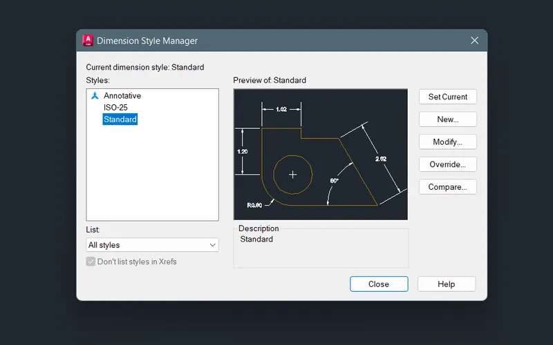
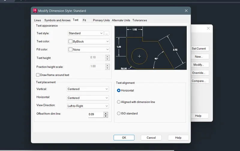
- Then, set the dimension as we need for the project
- We can set the text, symboland arrows, lines and the primary units as shown below
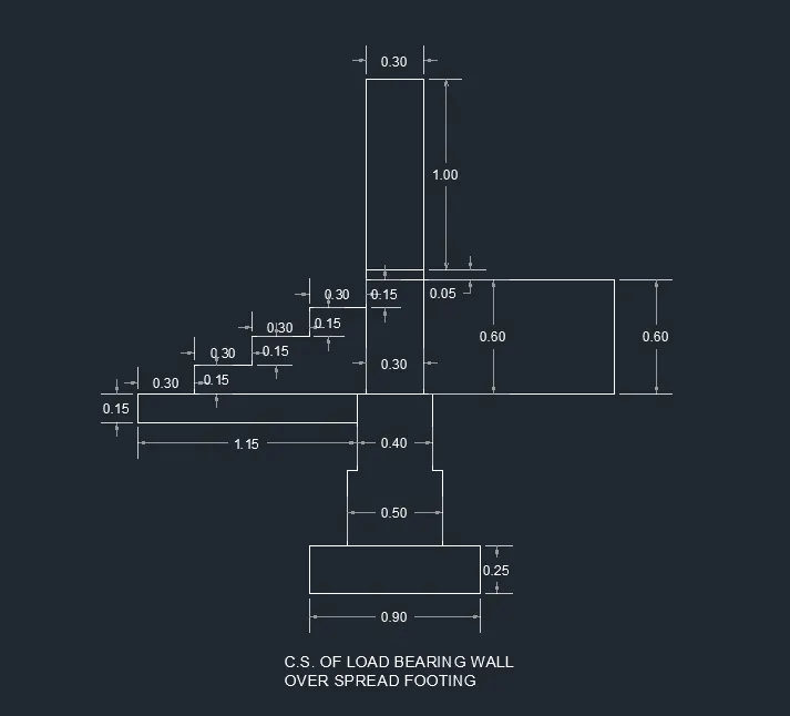
Step-3: To draw the cross-section of load bearing wall over spread footing
- Draw the sketch using the line command and the shortcut is L
- This drawing started from the point of footing bottom line
- And draw as the figure shows
- I refer the dimesions as given in the question
- And use the dimesion the shortcut is DIM
- The size of the text is 0.10
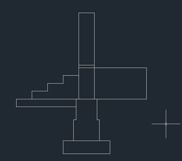
- This drawing is after mark the dimesions
- Take the screenshot using the snipping tool
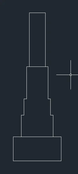
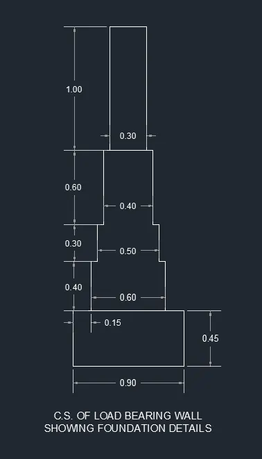
Step-4: To draw the cross-section of load bearing wall showing foundation details
- As the command have been used in previous drawing
- And mark the dimesions also
- Take the screenshot using the snipping tool
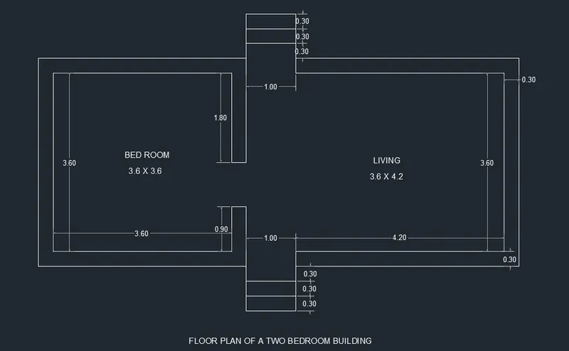
Step-5: To draw the floor plan of the given line drawing
- The floor plan was drawn using the line plan of a two bedroom building as in the question
- Here these commands are used: Line (L), Chamfer (CHA), Trim (TR), Extend (EX), MText (MT) and Offset (O)
- Then draw the as the given dimesions
- Line command is using for draw the all lines
- Chamfer is connect the two lines in the border
- Trim is to cut the excessive lines between the tow perpendicular lines
- Extend is extend to the next end line
- MText is to give a name of individual portions in the building and give a title of the drawing
- Offset is to make the wall lines in the drawing
- And take the screenshot using the snipping tool
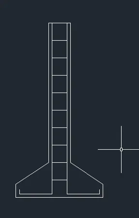
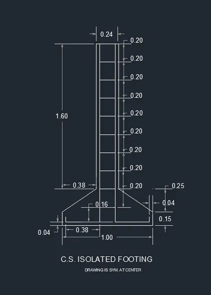
Step-6: To draw the cross-section of isolated footing
- This drawing is also using those commands as shown in the step-3
- And take the screenshot using the snipping tool
- The drawing is shown in below
Step-7: To draw the isometric view of the staircase
- In this drawing the view of the drawing haveto change as shown in figure
- These three types view is used in this drawing
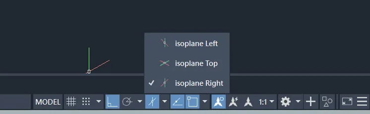
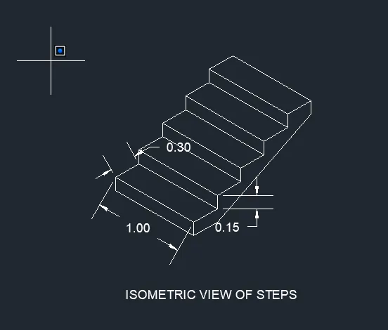
- And then draw the isometric view of the staircase
- Then, give the dimesion using the dimesion command (DIM)
- Give the title name using the MText command
- The isometric view of the staircase is shown below
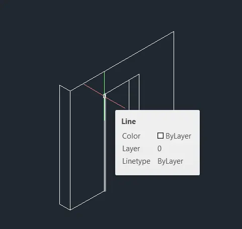
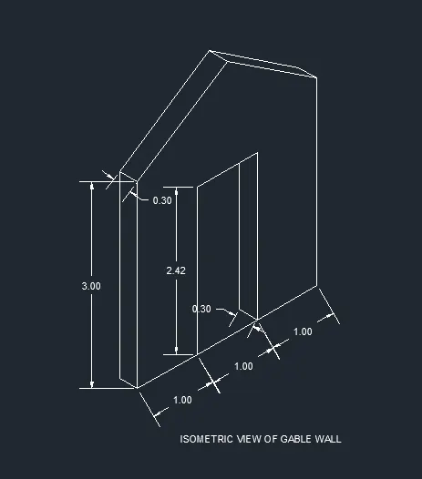
Step-8: To draw the isometric view of gable wall
- Here also use the isometric viewing command
- And take those three view of line and draw the gable wall drawing
- Give the dimensions as shown in above steps
- Take the screenshots using snipping tool
Result:
The drawing is drawn using those commands as shown in the detailed procedure and finish those drawings as given in the question attachment successfully using the AutoCAD 2023 software.