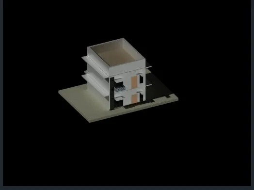
Project 2_Creating a 3D rendered model for a Residential Building in AutoCad
1.)
AIM
To Create a 3 dimensional model of the residential building with a rendered view.
Procedure
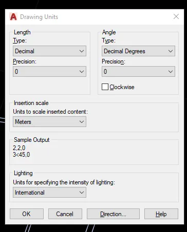
- set the units
- set dimesional style manager foe units
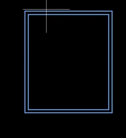
- Use the plyline and draw a rectagle.
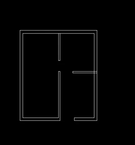
- use the pl line and make partician the wall.
- Set the layers as per the form.
- Set the colour.
- set the layers line type.
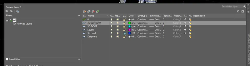
- Extrude the given lines.
- Extrude to the height of the 3.0m.
- Provide the hiden lines.
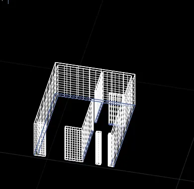
- Provid the walls
- set the layers in proper manner
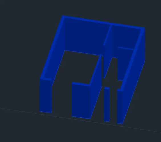
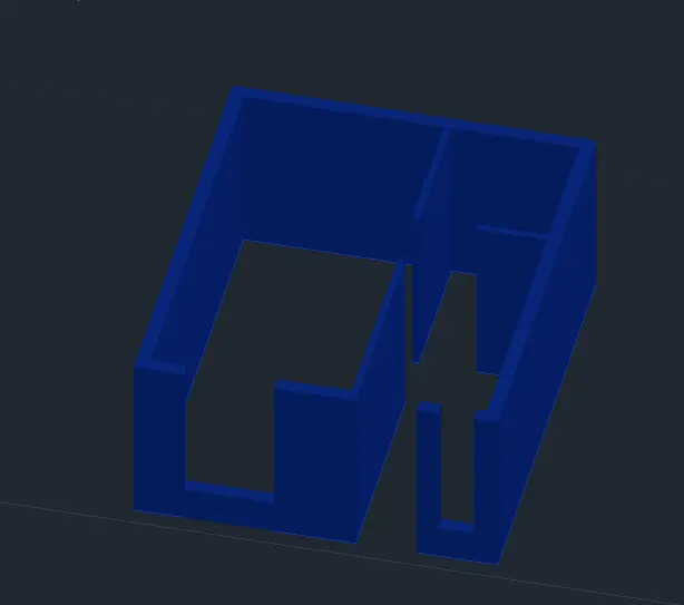
- Make boundary.
- So that it can be in solid state.
- Pick the oints in the layout.
- Seth the window.
- Extrude the wall to the sill height .6m.
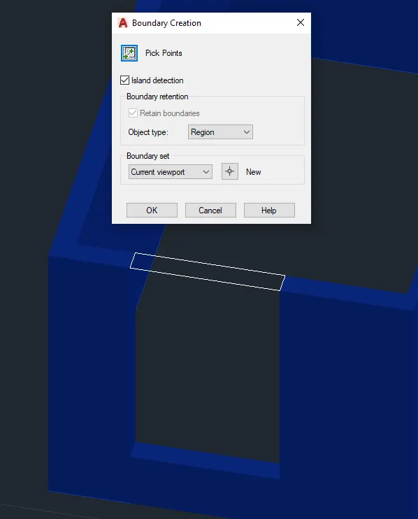
- Extrude the lintel level.
- Change the wall materials.
- Global generic misslienous material,
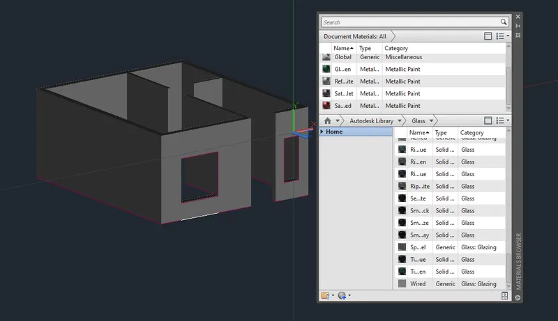
- Make the boundary of the selected portion for window.
- give th egiven materials
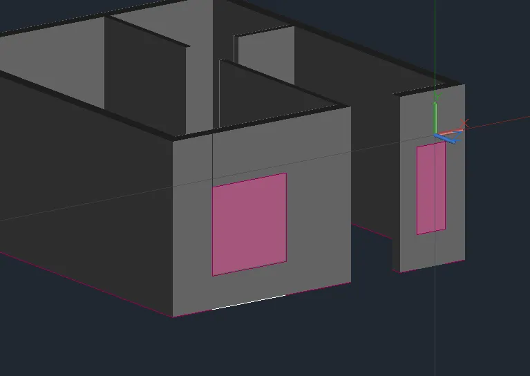
- Provide the openings.
- Provide the proper rectangle.
- Provide the materials.
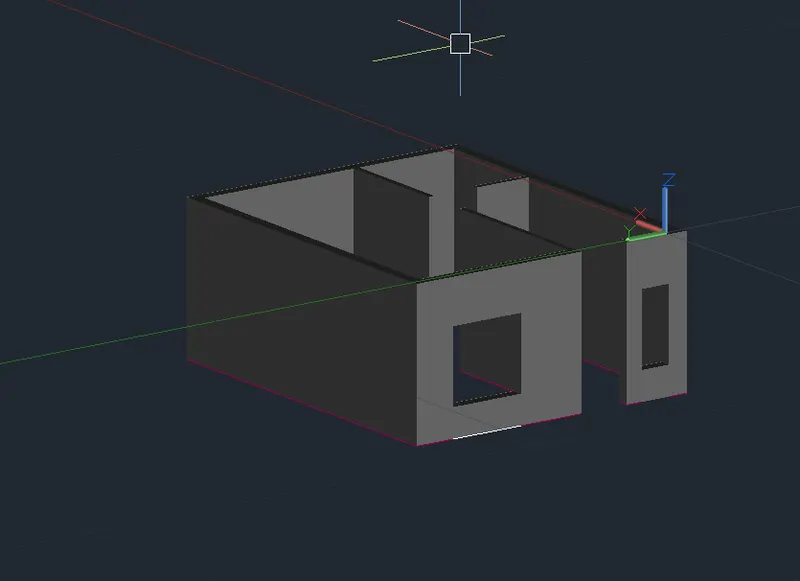
- provide the glass in the given portion.
- select it from the material browser.
- select the propewr glass.
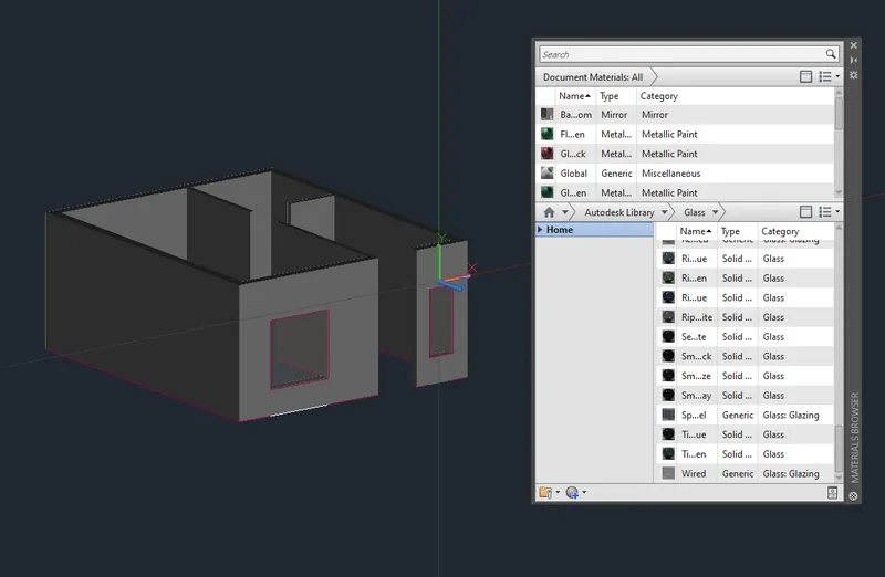
- Provide the tileing floor
- From the material browser.
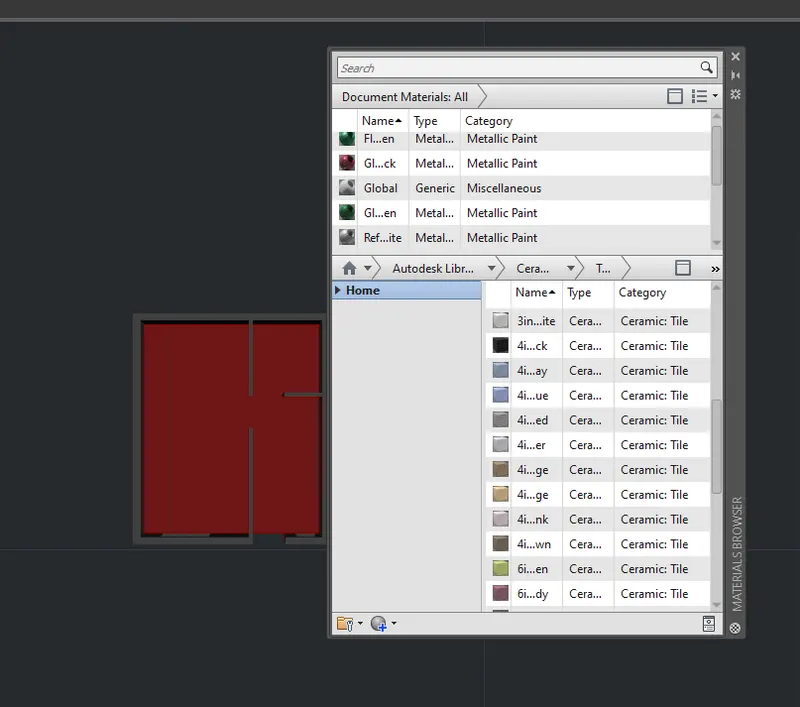
- Ther fore teh tile if fixed from the material browser .
- Put in the correct position.
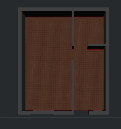
- Provide in corect measurement.
- opening sshould be in correct position.
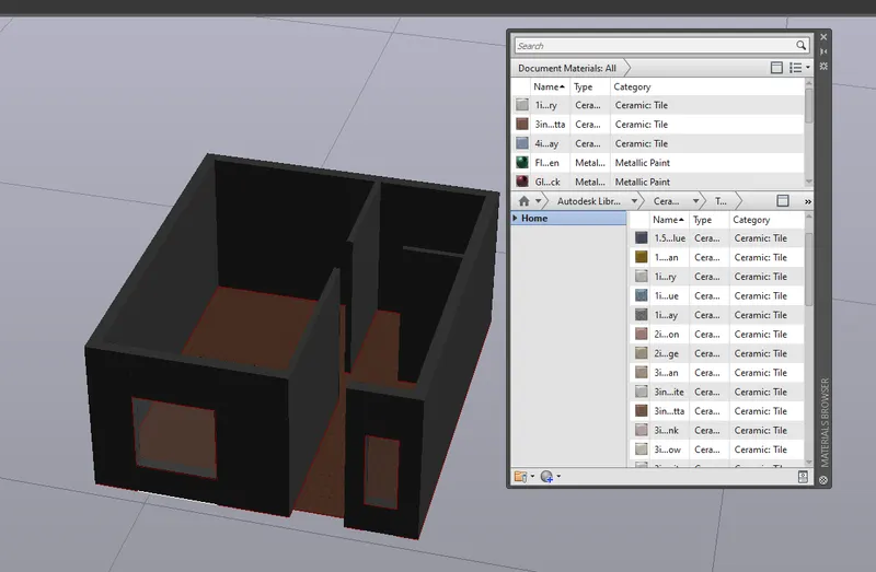
- Provid ethe door
- From the material browser.
- Corect position shopuld have to be done.
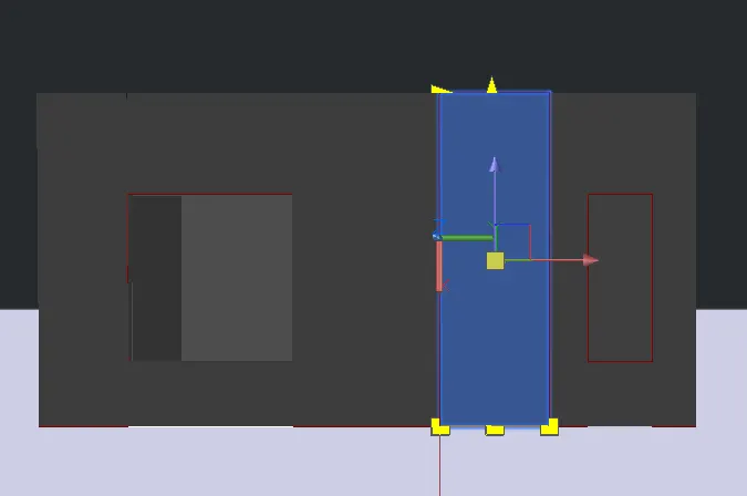
- Should select in layer.
- put dowN thw 3d-DOOR.
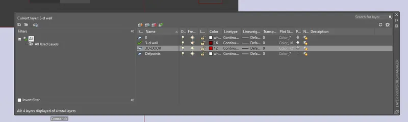
- The dor fixed from the material browser.
- wooden dorr is fixed.
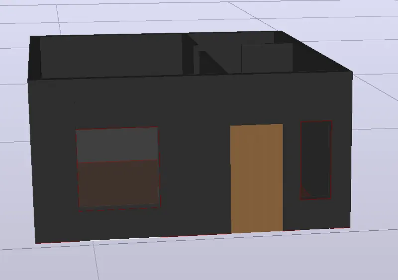
- The view is changed to parallel.
- from the given system is provided
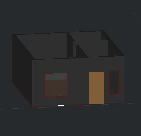
- The layers are fixed in the given form.
- Proper layers are fixed.
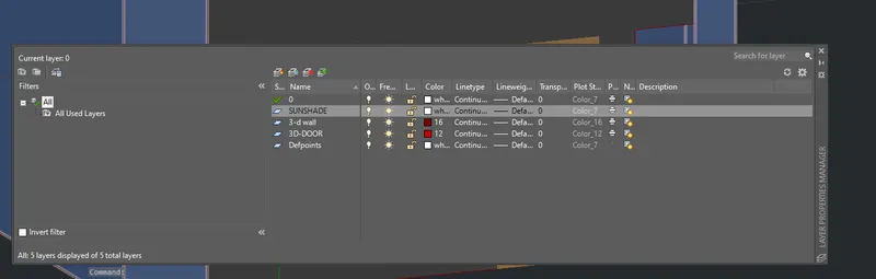
- The floor slab is fixed.
- peoper dimension provided.
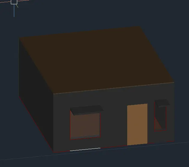
- The floor to floor connection is done.
- the floor copy is done.
- from one florr toi another.
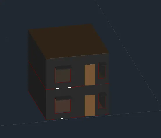
- The balcony is provided.
- Extruded from the given form.
- The stone is provided.
- the balcony is well setuped.
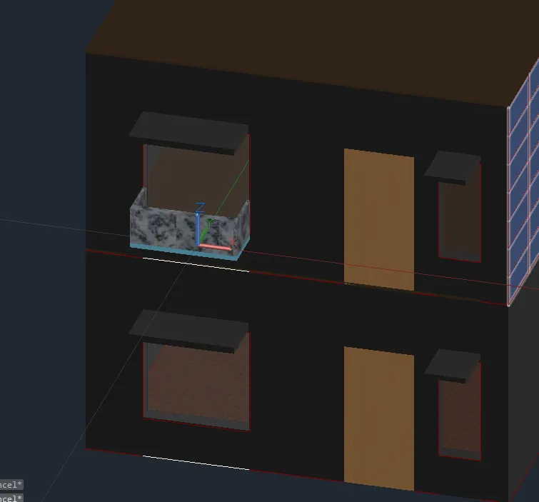
- The Match propertoies are done.
- Therefore the floor to floor connection is done.
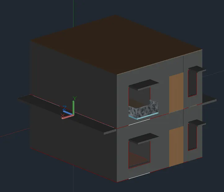
- The extrued part is done
- there are the elogation.
- In front odf the house.
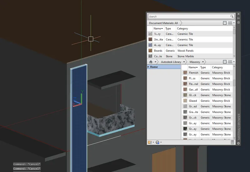
- Sunshade is created.
- In both sides.
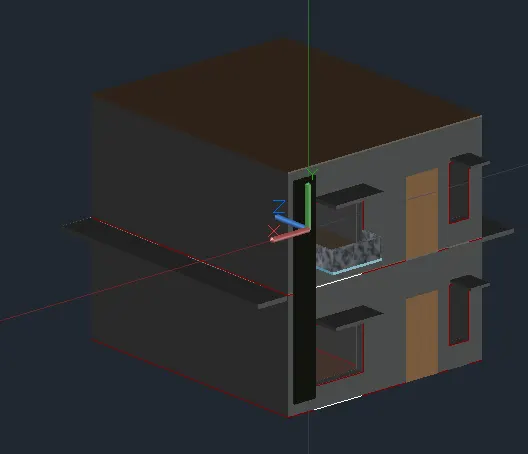
- The down ground is created.
- The material is provided from the material browser.
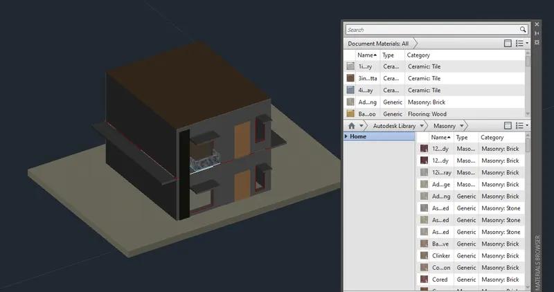
- The top slab is applied.
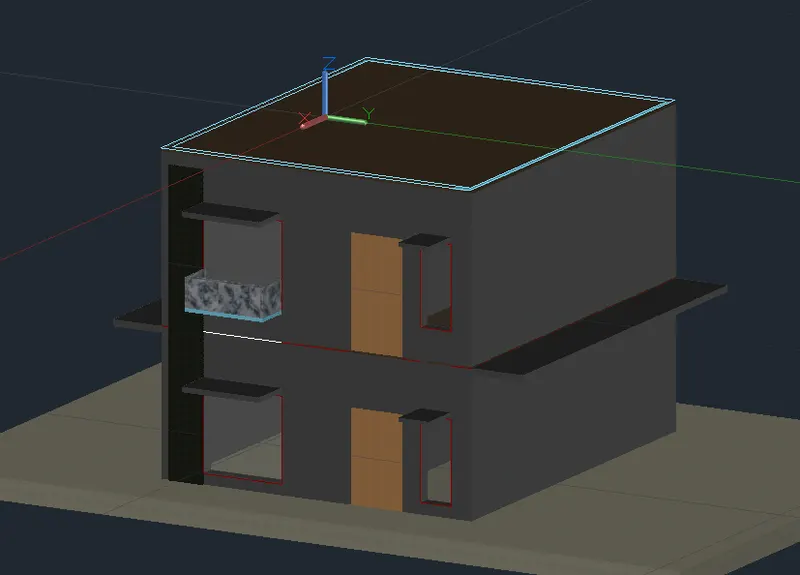
- The slab is done.
- Thew thickeness is assumed for the slab.
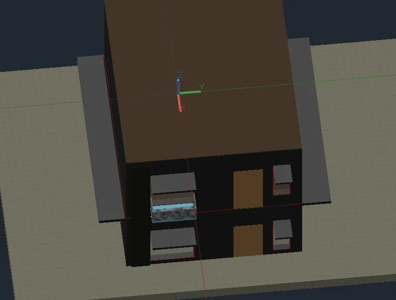
- The openings are done.
- In teh general form.
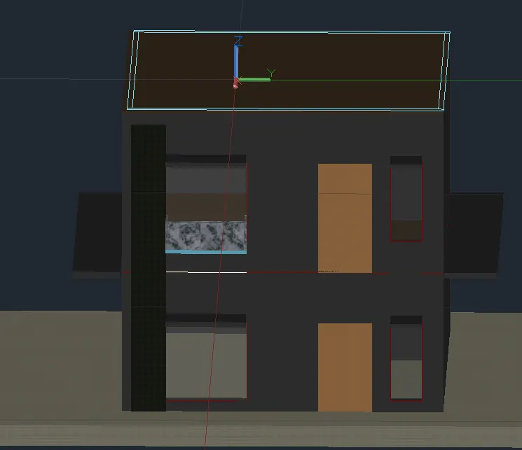
- ucs is fixed every object.
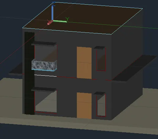
- The glasses is vissible one.
- The balcony is provided.
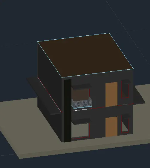
- The slab is done withj general form.
- The sunshade is drawn and copy pasted in the every side.
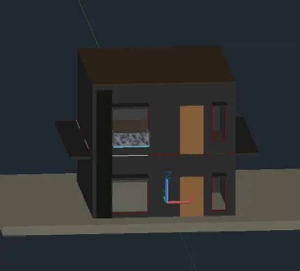
- The siunshade is done.
- through the lines in the form.
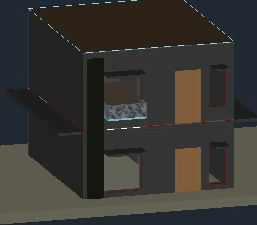
- THe sunshde is done.
- in every sides.
- in gneral position.
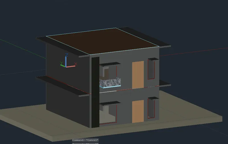
- The process is done for the parapet.
- the lines are drwan in the top of the slab.
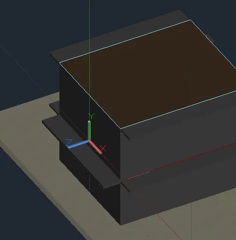
- The ucs is fixed in the every drawing
- The object is done every position.
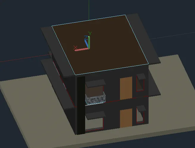
- The parapet is done from the subtraction.
- Then the parapet is doen every position.
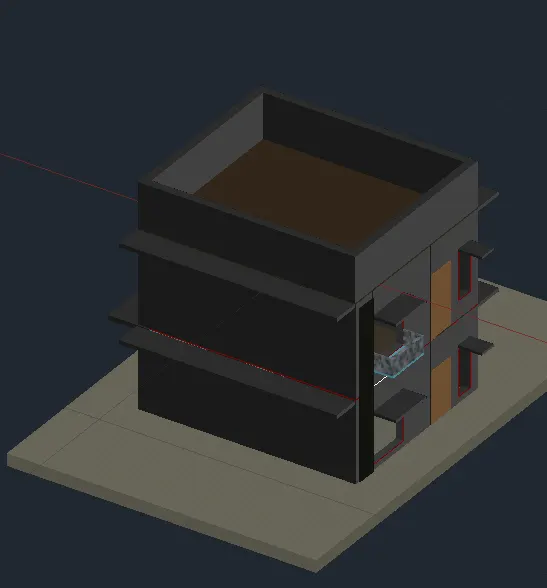
- The parapet is done in the general form.
- The line is exrtuded
- Then the extruded part is subtracted.
- To get the parapet.
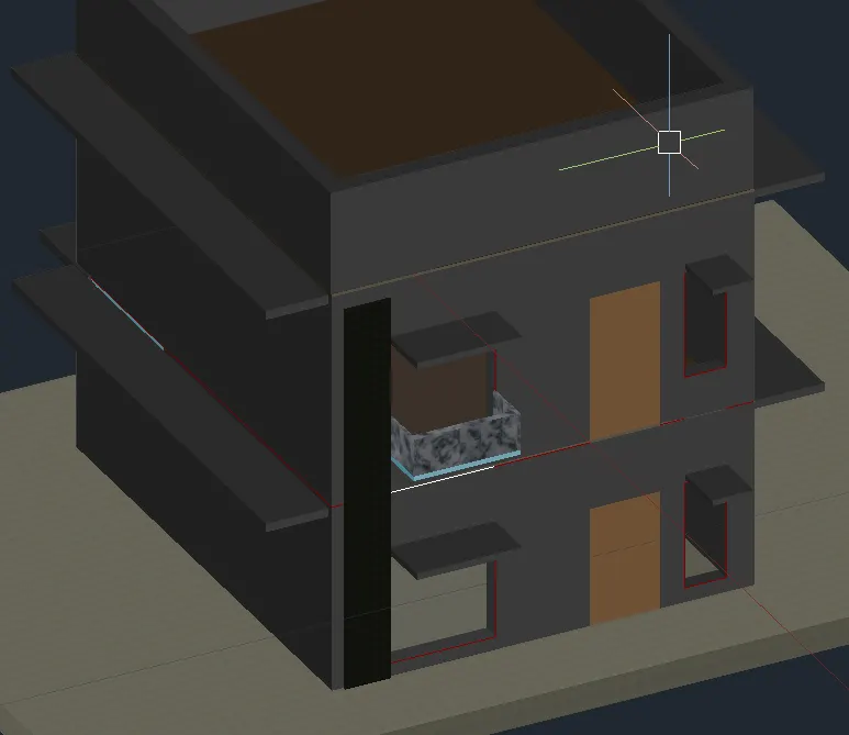
- The rendering process is allowed.
- From the gieven form.
- Rendering is done in the form.
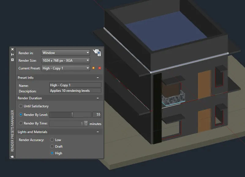
- In the give form the rendering is selected.
- The rendering is done in th egiven pixel.
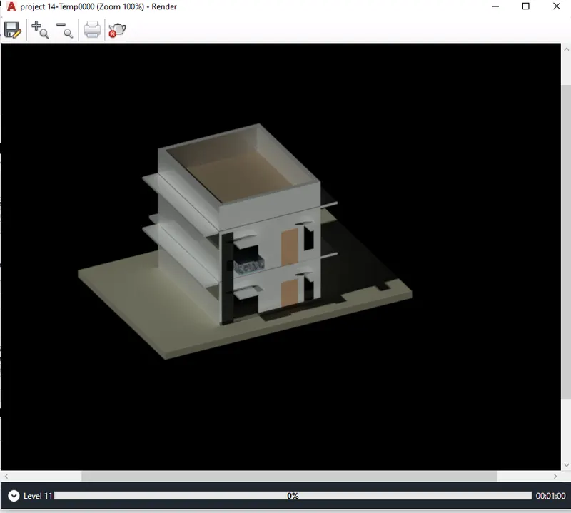
- The renderoing process is done.
- In the process thre rendering is done
- The general rendering process is done here.
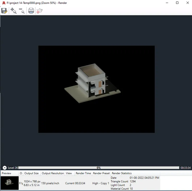
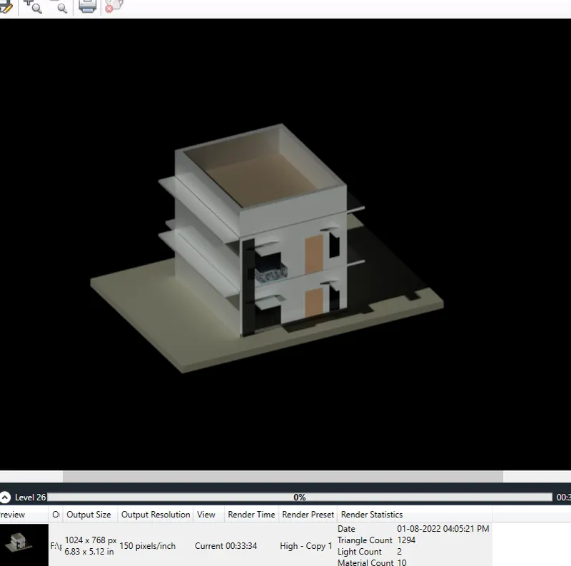
Result
- Thus the rendering is done in the form.
- The given lsyout is taken from the rendering