Project 2_Creating a 3D rendered model for a Residential Building in AutoCad
Aim: To Create a 3 dimensional model of the residential building with a rendered view.
Intorduction: To Create a 3 dimensional model of the residential building with a rendered view using Autocad.
Procedure:
- In the command prompt type limmax >100',100'
- In the command prompt type limits > 0',0'
- In the command prompt type zoom > a
- Go to the top view.
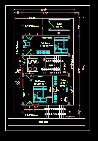
- First we need to take the 2D drawing in Autocad to create the 3D model.
- 2D model is attached below which is to be taken for 3D design.
-
- After taking the 2D drawing, now we have to convert the drawing in to 3d view.
- By taking the views in custom view we can get the 3d view from the drawing.
- Then by using line command draw te lines for clear visibility of 3d view.
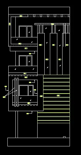
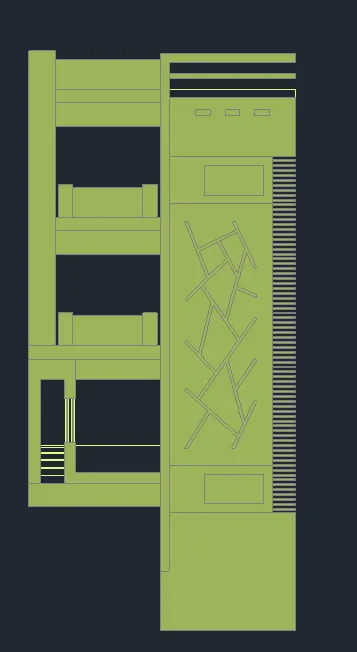
- Then the front elevation part is to be by our own design.
- Finally the front view of the drawing is attached below.
-
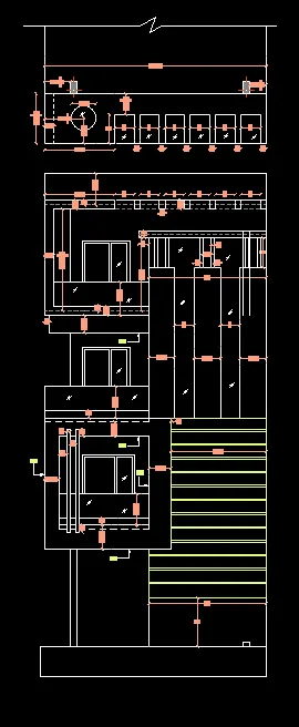
- Then as per the client requirement we have to show the floor areas.
- And at the top of the floor, there should be a overhead water tank.
- As per vaastu we have to mention the place where it is.
-
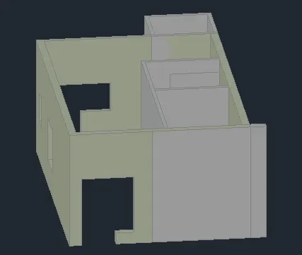
- Now taking the ground floor area first we have to create the layers separately.
- Then taking boundary command and select the outer portion.
- Then by using extrude command extrude the drawing to the floor height.
- In the same way extrude all the wall areas inside the room areas also.
- Leave the window and door portion areas.
- And by using union command, combine all the wall portion areas.
-
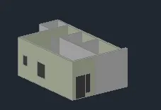
- Now after extruding the wall portions, take the window area.
- Take the window portion with the correct dimensions, then draw the inner lines for the window.
- By using bo command, apply the material for the window panel, window frame and window.
- Now by using subtract command,apply the material to the window portion separetly.
- After preparing the window, now copy the window to the window portion areas in the building.
- In the same way prepare the door frame and complete the door areas also as attached below.
-
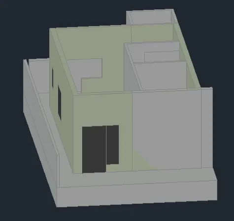
- Now we have to prepare the compound wall for the building.
- Take the plinth portion area and by taaking the floor area by using solid edit command,
- Take the small rectangle and apply extrude command for extruding the parapet wall.
- Now in the extrude command take the path and extrude through out the path.
- Then move the wall to the plinth wall, now parapet wall is ready as shown in the below attachment.
-
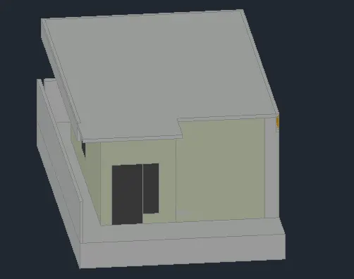
- Then now we have to place the slab at the floor height area.
- Now take the rectangle command and draw the rectangle at the top of the wall.
- this rectangle has to draw from the inner wall area from one corner to another corner point.
- By using UCS icon, draw the rectangle.
- Then extrude the rectangle to the slab height as shown in the below attchment.
-
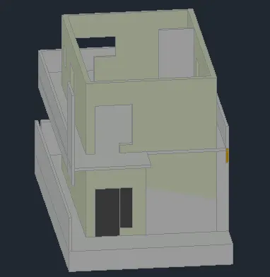
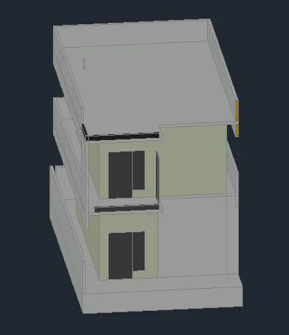
- Now we have to take number of floor areas.
- We have to copy the wall portion of the ground floor area, then to the slab height.
- Up to number of floors we have to take the wall portion areas by copy command to the slab height.
- After that, we have to copy the windows and door areas as shown in the below attachment.
-
- Then after copying the floor areas, at the top floor we hae to shown the parapet wall.
- Now hide the floor area, so that we can take from the wall portion easily.
- Take the rectangle for the outer portion of the wall at the top floor and do the offset for the rectangle.
- Now do the region for the rectangle.
- Extrude the regio portion to the parapet height as shown in the below attachment.
-
-
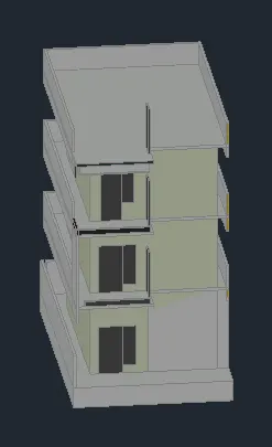
- After preparing the floor areas we have to design for the front view of the building.
- By using rectangle command, we have to design for the balcony area.
- For this by using plan command also we have to take the glass material for the requirement.
- Now after that apply the material to the portion.
-
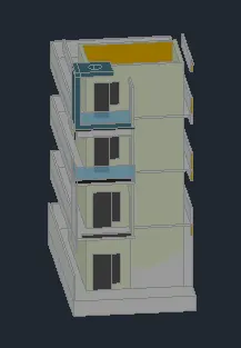
- After preparing the floor areas we have to design for the front view of the building.
- By using rectangle command, we have to design for the front view of the drawing.
- For this by using plan command also we have to take the front view of the building.
- Now after that apply the material to the portion.
-
-
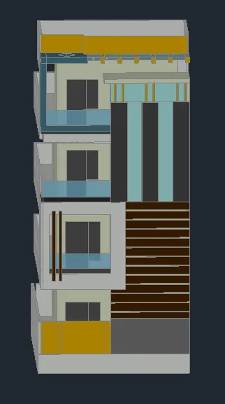
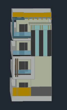
- After completing 3d drawing, now we have to take the view by rotating in the 3d oribit view.
- Back view of the drawing is taken and attached below.
-
Result:-