Project 2_Creating a 3D rendered model for a Residential Building in AutoCad
AIM: -
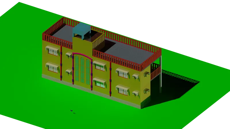
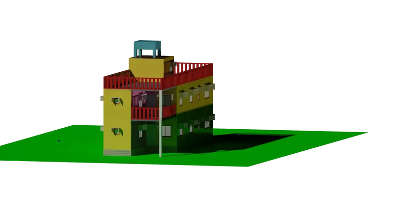
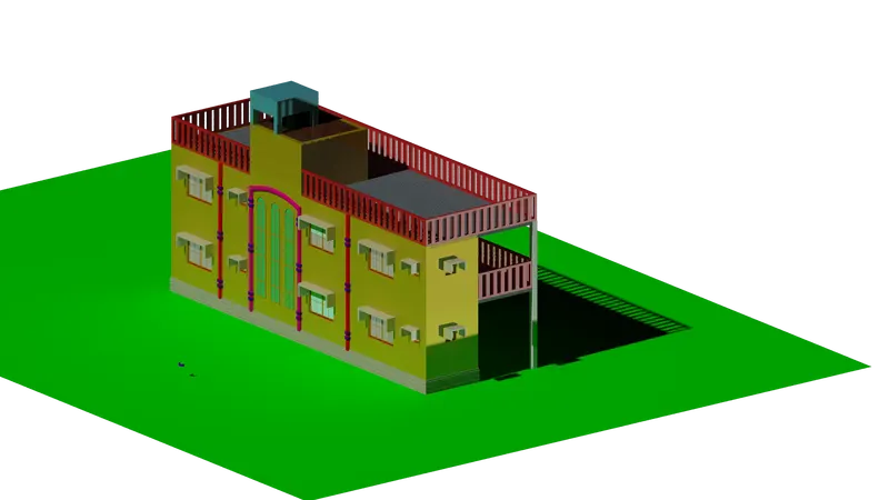
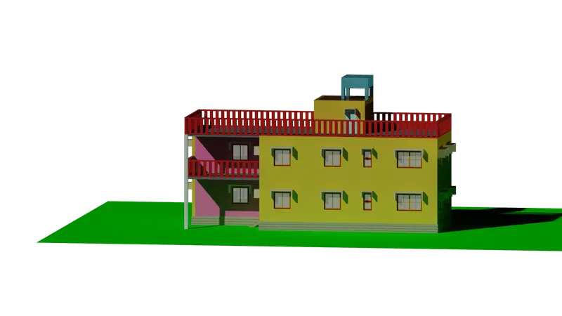
Create a 3D model of a Residential Building.
Apply Material to the Building.
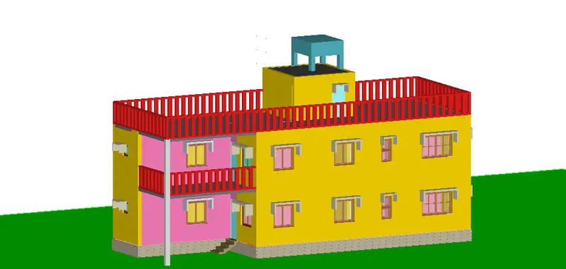
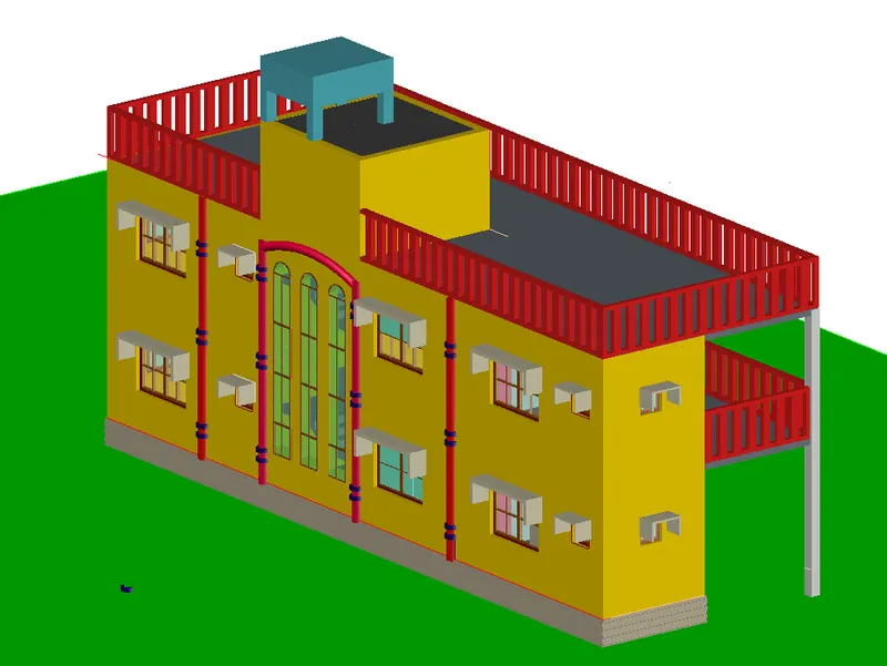
Create a render view of the model.
PROCEDURE: -
Start the AutoCAD with units as IMPERIAL
Set the Units to ENGINEERING.
In RIBBON, got to VIEW palette.
In VIEW, go to Viewport tools and turn on the UCS icon, NAVIGATION bar, and VIEW CUBE
Switch the Workspace to 3D MODELLING
Set the VIEW CONTROL to TOP
Type LAYERS
Create New Layer: 2D-Floor Plan
Assign Colour to the Layer.
Draw the Floor Plan under the created Layer.
Open the PROJECT_8 file
Type COPY
Select the Plan
Select the base Point
Paste the drawing in the Current file.
Draw the Floor Plan under the created Layer.
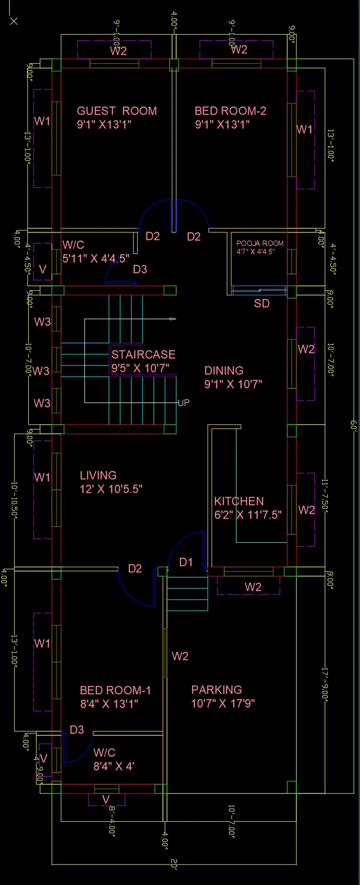
Set the VIEW CONTROL to FRONT
Type LAYERS
Create New Layer: 2D-Elevation
Assign Colour to the Layer.
Open the PROJECT_8 file
Type COPY
Select the Plan
Select the base Point
Paste the drawing in the Current file.
Draw the Elevations under the created Layer.
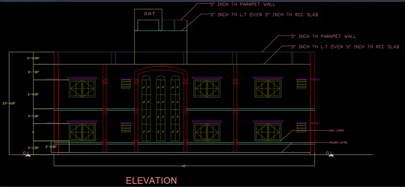
Set the VIEW CONTROL to SE ISOMETRIC
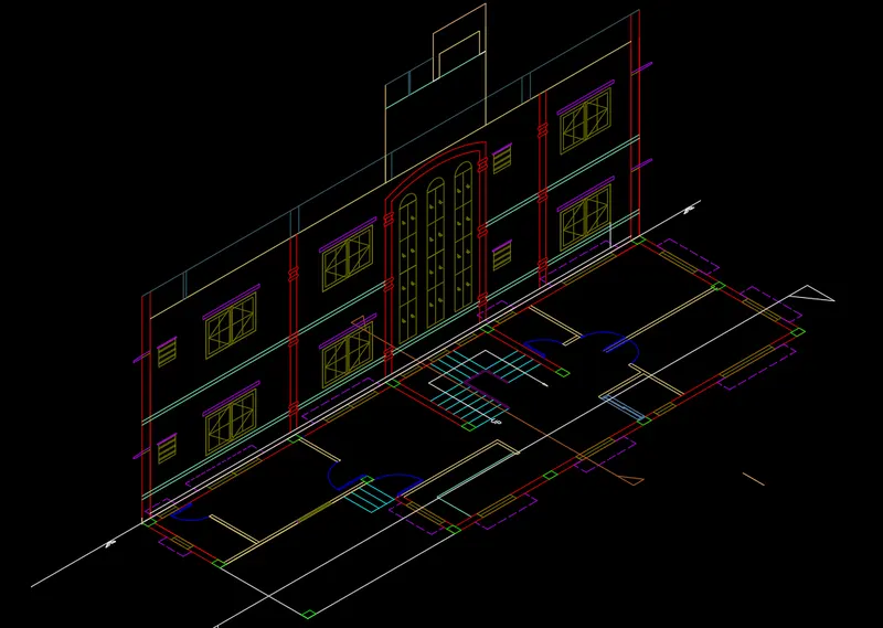
Type ALIGN
Select objects to align
Choose 1st Source point as point on Elevation
Choose 1st destination point as point on plan
Choose 2nd Source point as point on Elevation
Choose 2nd destination point as point on plan.
Press Enter.
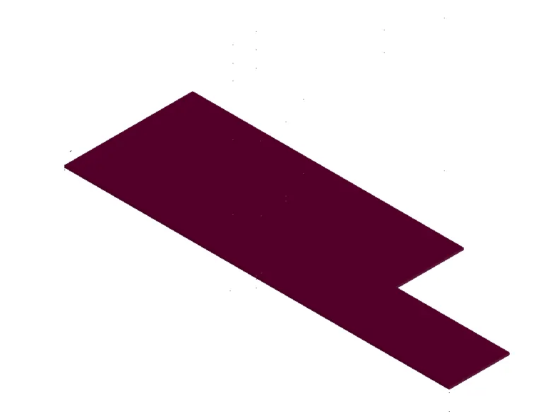
Create 3D model of FLOOR SLAB
Type LAYERS
Create New Layer: 3D- FLOOR SLAB
Assign Colour to the Layer.
Set the current Layer as 3D- ROOF SLAB.
Type LINE
Draw Rectangle as per the floor plan.
Press ENTER.
Type BOUNDARY
Object Type: Region
Pick points as the internal points on the SLAB.
Press Enter
Type EXTRUDE
Select the SLAB.
Enter the Height for Extrusion: 5” units
Press Enter.
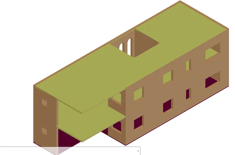
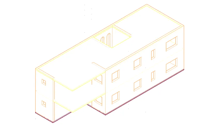
Create 3D model of
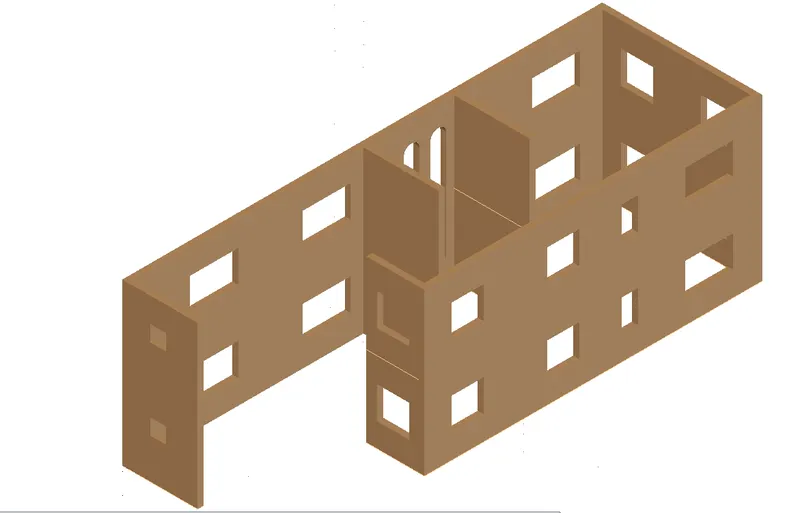
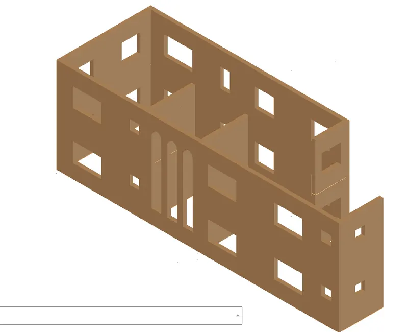
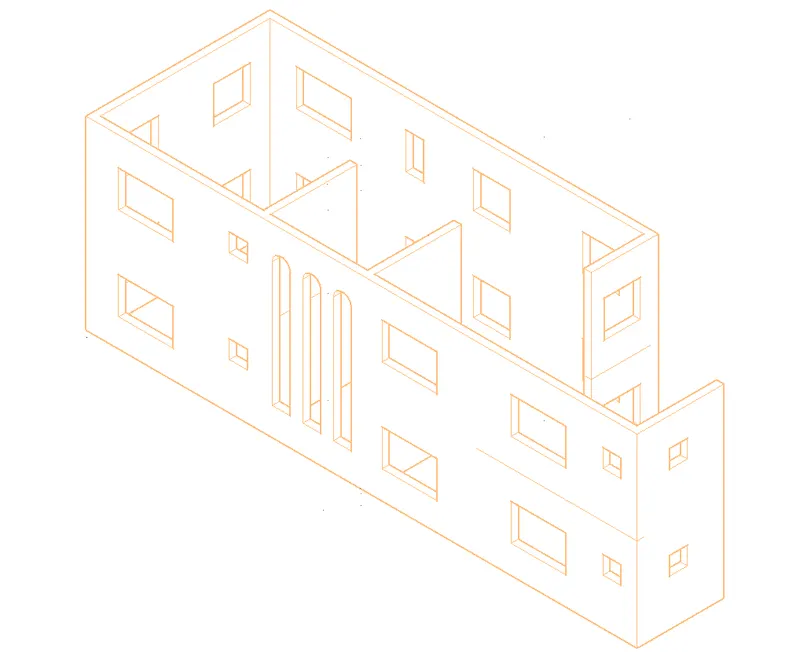
1] OUTER WALLS with Window Openings of GROUND FLOOR and FIRST FLOOR
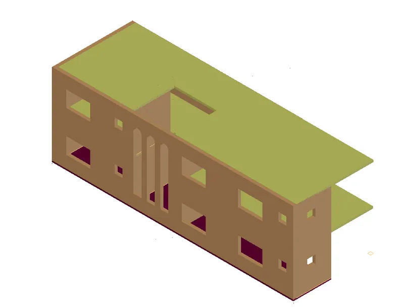
2] ROOF SLABS WITH STAIRCASE OPENING OF GROUND FLOOR AND FIRST FLOOR
Type LAYERS
Create New Layer: 3D-OUTER WALLS
Assign Colour to the Layer.
Set the current Layer as 3D-OUTERWALLS
Type BOUNDARY
Object Type: Region
Pick points as the internal points on the WALLS.
Press Enter
Type EXTRUDE
Select the WALLS
Enter the Height for Extrusion: 10’-1” units.
Turn off the 3D-OUTER WALL layer.
Now create window openings for size:
W1= 6'x 4' units
w2= 4' x 4' units.
V= 2' x 2' units.
Type LAYERS
Create New Layer: 3D-WINDOWS
Assign Colour to the Layer.
Set the current Layer as 3D-WINDOWS
Type LINE
Draw Rectangle over the windows in Floor Plan.
Copy the Rectangles to the Sill Level from Elevation.
Press Enter.
Type EXTRUDE
Select the windows
Enter the Height for Extrusion: 4’ units.
Press Enter
Type SUBTRACT
Select the Outer Walls
Press Enter
Select the Windows
Press Enter
Openings for the windows are created.
Type UNION
Select all the 3D-OUTER WALLS drawn
Press Enter
Type LAYERS
Create New Layer: 3D- ROOF SLAB
Assign Colour to the Layer.
Set the current Layer as 3D- FLOOR SLAB.
Type LINE
Draw Rectangle of size:20’ x 60’ units. as per the floor plan.
Press ENTER.
Type BOUNDARY
Object Type: Region
Pick points as the internal points on the SLAB.
Press Enter
Type EXTRUDE
Select the SLAB.
Enter the Height for Extrusion: 5” units
Press Enter.
Place the Roof SLAB at the Outer Wall Height
Type Rectangle
Draw Rectangle of size 9'5" x 10'7" units from Floor Plan.
Press Enter
Type EXTRUDE
Select the SLAB.
Enter the Height for Extrusion: 1' units
Press Enter.
Type SUBTRACT
Select the Roof Slab
Press Enter
Select the Rectangle
Press Enter
Opening for the Staircase is created.
Type COPY
Select the WALLS and ROOF SLAB
Choose the base point
Locate the walls at appropriate position.
Press OK
First Floor OUTER WALLS and ROOF SLAB are created.
Type UNION
Select all the 3D-OUTER WALLS drawn
Press Enter
Create 3D model of
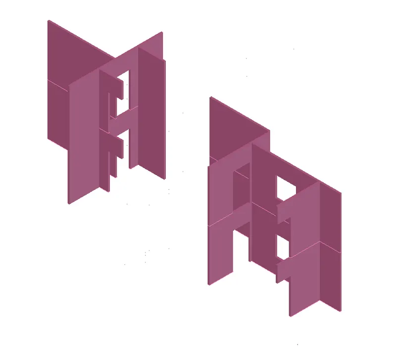
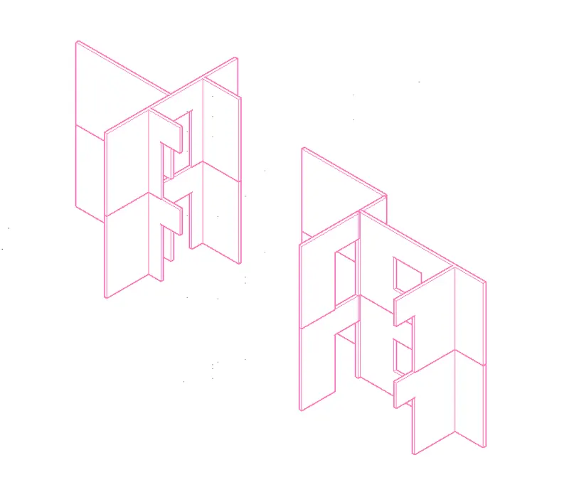
1] INNER WALLS of Ground Floor and First Floor
2] DOORS of Ground Floor and First Floor
Turn OFF the all SLABS layers
Type LAYERS
Create New Layer: 3D-INNER WALLS
Assign Colour to the Layer.
Set the current Layer as 3D-INNERWALLS
Type BOUNDARY
Object Type: Region
Pick points as the internal points on the WALLS.
Press Enter
Type EXTRUDE
Select the WALLS
Enter the Height for Extrusion: 10’-1” units.
Turn off the 3D-OUTER WALL layer.
Create WINDOW OPENINGS in the WALLS
W1= 6'x 4' units
w2= 4' x 4' units.
V= 2' x 2' units.
Type LAYERS
Create New Layer: 3D-WINDOWS
Assign Colour to the Layer.
Set the current Layer as 3D-WINDOWS
Type LINE
Draw Rectangle over the windows in Floor Plan.
Copy the Rectangles to the Sill Level from Elevation.
Press Enter.
Type EXTRUDE
Select the windows
Enter the Height for Extrusion: 4’ units.
Press Enter
Type SUBTRACT
Select the Outer Walls
Press Enter
Select the Windows
Press Enter
Openings for the windows are created.
Type UNION
Select all the 3D-INNER WALLS drawn
Press Enter
Type UNION
Select all the 3D-INNER WALLS drawn
Press Enter
Create 3D-Model of DOORS of SIZE
D1= 3’-3” x 7’ including Lintel
D2= 3’-0” x 7’ including Lintel
D3= 2’-6” x 7’ including Lintel
Set the Visual style to 2D WIREFRAME
Set the VIEW CONTROL to SW-ISOMETRIC
Type LINE
Draw Rectangle over the Floor Plan for the Door
Press Enter
Type LAYERS
Create New Layer: 3D-DOOR
Assign Colour to the Layer.
Set the current Layer as 3D-DOOR.
Type BOUNDARY
Object Type: Region
Pick points as the internal points on the DOOR.
Press Enter
Type EXTRUDE
Select the DOOR.
Enter the Height for Extrusion: 6’-8” units.
Press Enter.
Type LAYERS
Create New Layer: 3D-LINTEL
Enter the Height for Extrusion: 4” units.
Press Enter.
Type COPY
Select the WALLS and DOORS
Choose the base point
Locate the walls at appropriate position.
Press OK
First Floor WALLS and DOORS are created.
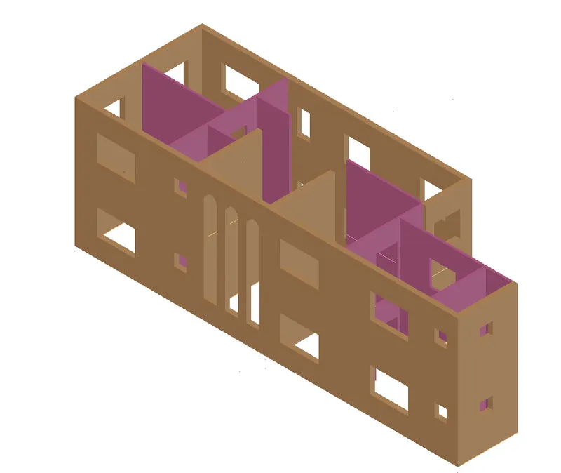
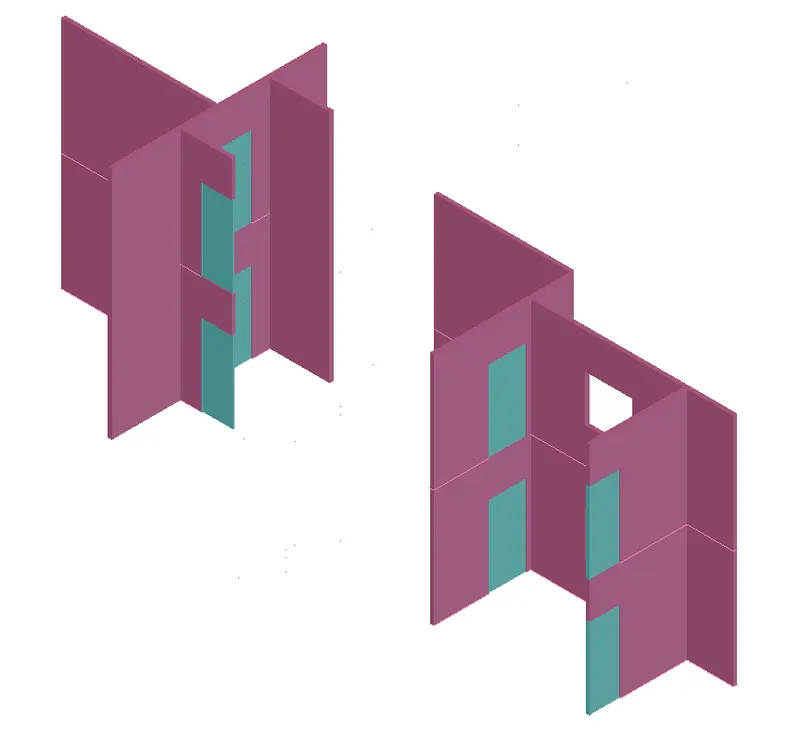
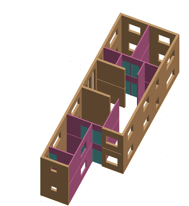
Create 3D model of
1] WINDOWS
2] SHADES
W1= 6'x 4' units
w2= 4' x 4' units.
V= 2' x 2' units.
Type LAYERS
Create New Layer: 3D-Window Frame
Assign Colour to the Layer
Create New Layer: 3D-Window Mullion
Assign Colour to the Layer
Create New Layer: 3D-Window Glass
Assign Colour to the Layer.
Select the 3D-Window Frame as Current Layer
Create windows of size 6’ x 4’ units
Type BOUNDARY
Object Type: Region
Pick points as the internal points on the Window.
Press Enter
Type SUBTRACT
Select the Outer panel of window
Press Enter
Select the Inner panels of window to subtract
Press Enter
Type EXTRUDE
Select the 3D-Window Frame
Enter the Height for Extrusion: 4” units.
Select the 3D-Window Mullion as Current Layer
Type SUBTRACT
Select the 2nd panel of window
Press Enter
Select the Inner panel of window to subtract
Press Enter
Type EXTRUDE
Select the 3D-Window Mullion
Enter the Height for Extrusion: 3” units.
Select the 3D-Window Glass as Current Layer
Type BOUNDARY
Object Type: Region
Pick points as the internal points on the window panels.
Press Enter
Type EXTRUDE
Select the 3D-Window GLASS
Enter the Height for Extrusion: 2” units.
Type MOVE
Select all the Window panels
Select the Base Point
Specify the next point: @0,0, -4”
Press Enter
Follow the same procedure for all sizes of windows
Now create SHADES for each window size 6’ x 4’ units
Type LAYERS
Create New Layer: 3D-SHADES
Assign Colour to the Layer.
Set the current Layer as 3D-SHADES.
Type LINE
Draw shades from Elevation drawing
Type BOUNDARY
Object Type: Region
Pick points as the internal points on the shades.
Press Enter
Type EXTRUDE
Select the SHADES.
Enter the Height for Extrusion: 18” units
Press Enter.
Now create SHADES for each window size 4’ x 4’ units
Type LAYERS
Create New Layer: 3D-SHADES
Assign Colour to the Layer.
Set the current Layer as 3D-SHADES.
Type LINE
Draw shades from Elevation drawing
Type BOUNDARY
Object Type: Region
Pick points as the internal points on the shades.
Press Enter
Type EXTRUDE
Select the SHADES.
Enter the Height for Extrusion: 18” units
Press Enter.
Now create SHADES for each ventilator size 2’x 2’ units
Type LAYERS
Create New Layer: 3D-SHADES
Assign Colour to the Layer.
Set the current Layer as 3D-SHADES.
Type LINE
Draw shades from Elevation drawing
Type BOUNDARY
Object Type: Region
Pick points as the internal points on the shades.
Press Enter
Type EXTRUDE
Select the SHADES.
Enter the Height for Extrusion: 18” units
Press Enter.
All Windows and Shades are Created.
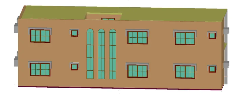
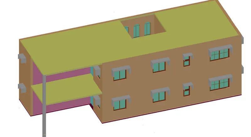
Create 3D model of STAIRCASE AND STEPS AT ENTRANCE
Type LAYERS
Create New Layer: 3D-STAIRCASE
Assign Colour to the Layer.
Set the current Layer as 3D-STAIRCASE
Set the VIEW CONTROL to SE ISOMETRIC
Type LINE
Draw Elevation of the stairs with raise 7" units and Tread 11" units. in YZ Axis.
Provide 2 Landings of 3' x 3'11"
Provide slab thickness as 4" units.
Type BOUNDARY
Object Type: Region
Pick points as the internal points on the STAIRS.
Press Enter
Type EXTRUDE
Select the STAIRS.
Enter the Height for Extrusion: 3’-11” units. in X-axis. direrction
Press Enter
Type LAYERS
Create New Layer: 3D-BALUSTRADES
Assign Colour to the Layer.
Set the current Layer as 3D-BALUSTRADES.
Set the VIEW CONTROL to TOP
Type Circle
Select centre, diameter option
Specify diameter: 1” units.
Press Enter
Type BOUNDARY
Object Type: Region
Pick points as the internal points on the circle.
Press Enter
Set the VIEW CONTROL to SE ISOMETRIC
Type EXTRUDE
Select the Balustrade
Enter the Height for Extrusion: 3’ units. in Y axis
Press Enter
Type COPY
Select the Balustrade
Specify the base point: corner of the step.
Place the balustrade on all steps.
Press Enter.
Type LAYERS
Create New Layer: 3D-RAILING.
Assign Colour to the Layer.
Set the current Layer as 3D-RAILING.
Type LINE
Select centre of the Balustrade and draw the passing through the centres of the balustrades.
Press Enter.
Type Circle
Select centre, diameter option
Specify diameter: 1” units.
Press Enter
Type SWEEP
Select the object as circle
Select the path as the Line drawn through the centres of balustrades.
Press Enter
Type UNION
Select all the Stairs, Balustrades and Railing.
Press ENTER
Type COPY
Select the Staircase
Choose the base point.
place it at the desired location.
Staircase is created for the Ground Floor and first Floor
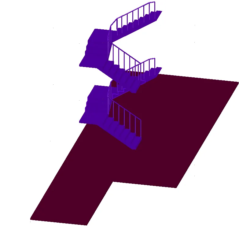
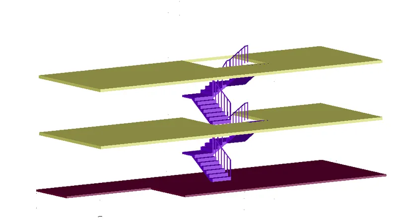
Set the VIEW CONTROL to SE ISOMETRIC
Type LINE
Draw the stairs with raise 7" units and Tread 11" units. in YX Axis. from the Floor Plan
Provide slab thickness as 4" units.
Type BOUNDARY
Object Type: Region
Pick points as the internal points on the STAIRS.
Press Enter
Type EXTRUDE
Select the STAIRS.
Enter the Height for Extrusion: 3’ units. in Z-axis. direrction
Press Enter
STEPS at the ENTRANCE are created.
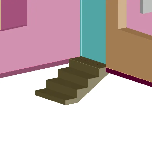
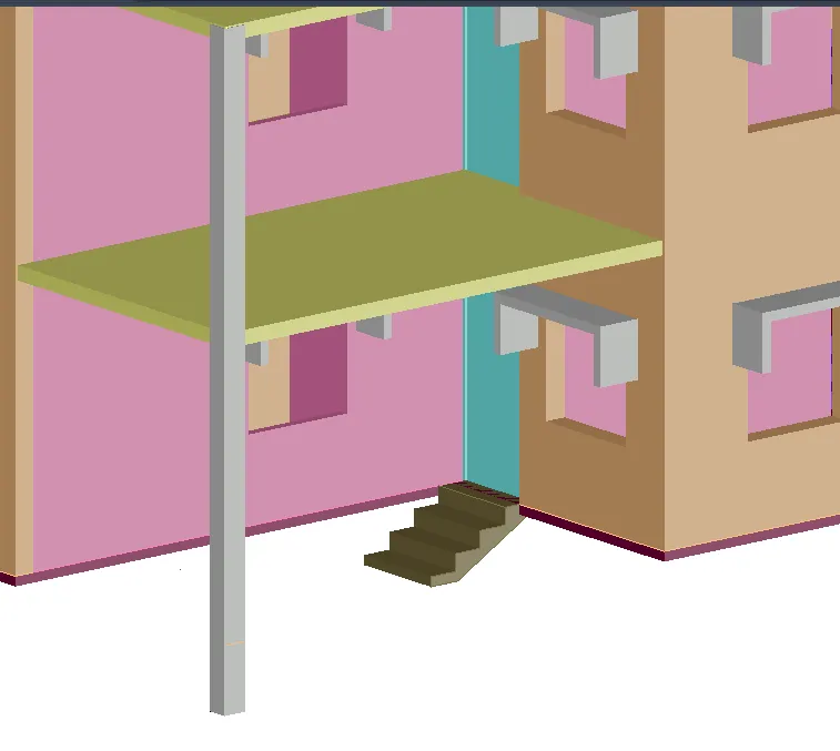
Create 3D model of
1] PARAPET WALL
2] PLINTH WALL
Type LAYERS
Create New Layer: 3D-PARAPET WALL.
Assign Colour to the Layer.
Set the current Layer as 3D-PARAPET WALL.
Set the VIEW CONTROL to SE ISOMETRIC
Type RECTANGLE
Draw Rectangle of Size 20’ x 60’ units. in YZ plane.
Press ENTER
Type BOUNDARY
Object Type: Region
Pick points as the internal points on the Rectangle.
Press Enter
Type EXTRUDE
Select the Rectangle.
Enter the Height for Extrusion: 4” units. in X axis
Press Enter
Type RECTANGLE
Draw Rectangle of Size 8” x 12” units. in YZ plane.
Press ENTER
Type ARRAY
Select the Smaller Rectangle
Distribute it along the Bigger Rectangle with columns 15 and Rows 1
Press Enter
Type EXTRUDE
Select the smaller Rectangles.
Enter the Height for Extrusion: 6” units. in X axis
Press Enter
Type SUBTRACT
Select the Bigger Rectangle
Press Enter
Select the smaller Rectangles.
Press Enter.
Parapet Wall is ready.
Place the wall around the perimeter on top of the 1st Floor
Wherever the Length exceeds use SLICE command.
Type SLICE
Select the object as parapet wall.
Select 2 points perpendicular to the section to slice.
Pick point on the section to be retained.
Press Enter.
Type ROTATE3D
Select the Parapet Wall
Select the Y-Axis
Specify the angle: -90
Press Enter.
Type COPY
Select the Parapet Wall
Choose base point
Place it along the longer side of the building.
Press Enter.
Type SLICE
Select the object as parapet wall.
Select 2 points perpendicular to the section to slice.
Pick point on the section to be retained.
Press Enter.
Parapet Wall is created arround the building.
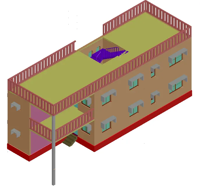
Set the VIEW CONTROL to SE-ISOMETRIC
Type LAYERS
Create New Layer: 3D-PLINTH WALL
Assign Colour to the Layer.
Set the current Layer as 3D-PLINTH WALL.
Type SECTION
Select the object as Floor Slab
Specify plane as XZ
Press Enter
Section of the Floor slab is formed.
Type LINE
Draw Rectangle of size 2” x 2’-1” units.
Press Enter.
Type RECTANGLE
Draw Rectangles of size 1” x 3” units
Place the smaller rectangles on the Bigger rectangle at centre.
Press Enter
Type SUBTRACT
Select the Bigger Rectangle
Press Enter
Select the Smaller Rectangles
Press ENTER
Type SWEEP
Select the Shape we created.
Select the path as Section from the Floor slab.
Press Enter.
Type MOVE
Select the Plinth Wall created.
Choose the base point.
Place it below the Floor slab.
Press Enter.
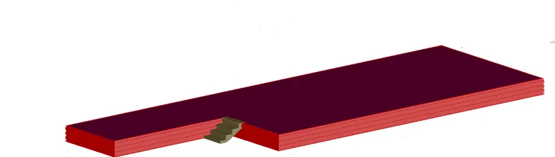
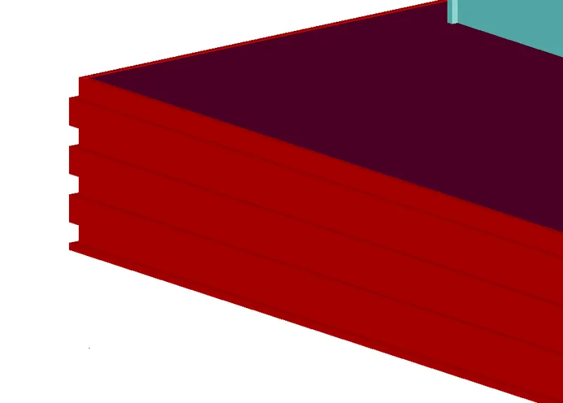
Create 3D- model of
1] STAIRCASE ROOM
2] ELAVATION OBJECTS.
3] O.H.T
Create walls of the staircase room
Type RECTANGLE
Draw Rectangle of size 9’5” x 10’7”
Press Enter
Type OFFSET
Specify the offset distance as 9”
Select the Rectangle and click outside the rectangle.
Press Enter
Select the 3D-OUTER WALL LAYER
Type BOUNDARY
Object Type: Region
Pick points as the internal points on the frame of the Rectangle.
Press Enter
Type EXTRUDE
Select the flooring.
Enter the Height for Extrusion: 7’-11” units.
Press Enter.
Walls are created.
Create Slab.
On top of the stair-case room
Draw Rectangle of size 9’5” x 10’7” units.
Type BOUNDARY
Object Type: Region
Pick points as the internal points on the SLAB.
Press Enter
Type EXTRUDE
Select the flooring.
Enter the Height for Extrusion: 5” units.
Press Enter.
Slab is created.
Create opening for Door.
Type RECTANGLE
Draw Rectangle of size 3’ x 6’-8” units.
Press Enter
Place the Rectangle at the location of the stairs.
Type EXTRUDE
Select the Rectangle
Enter the Height for Extrusion: 1’ units.
Press Enter.
Type SUBTRACT
Select the Wall
Press Enter
Select the Rectangle
Press Enter
Opening for the Door is Created.
Type COPY
Select the Door
Choose the base point.
Place it at the required location
Press Enter
Type LAYERS
Create New Layer: 3D-O.H. T
Assign Colour to the Layer.
Set the current Layer as 3D-O.H.T.
Set the VIEW CONTROL to SE-ISOMETRIC
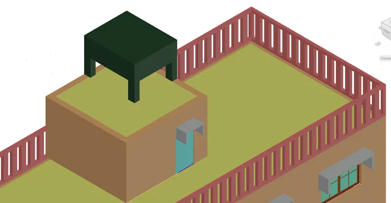
On top of the stair case room
Draw columns for the O. H. T in XZ plane.
Type Rectangle
Draw rectangles of size 9” x 9”
Place it at the corners of the O.H.T
Press Enter
Type EXTRUDE
Select the Rectangle.
Enter the Height for Extrusion: 2’5” units.
Press Enter.
Type Rectangle
Draw rectangle for O.H.T in XZ plane.
Press Enter
Type EXTRUDE
Select the Rectangle.
Enter the Height for Extrusion: 2’6” UNITS. in Y-axis.
Press Enter.
Place the O.H.T on the columns.
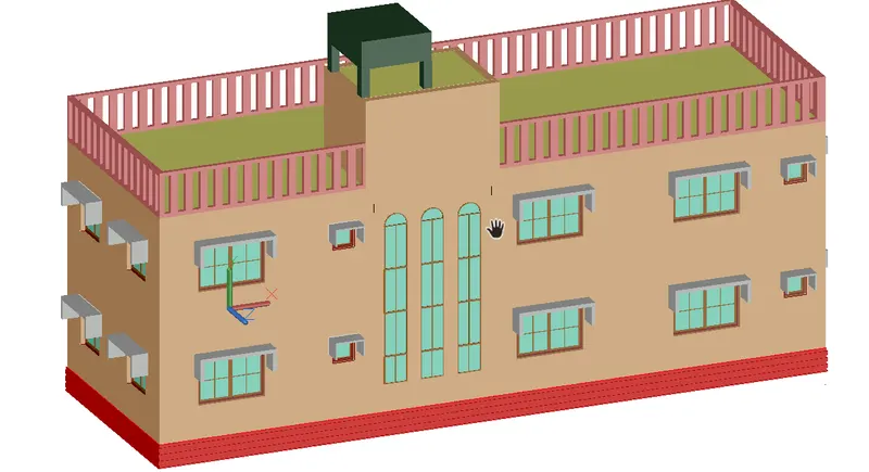
Type LAYERS
Create New Layer: 3D-ELEVATION OBJECTS
Assign Colour to the Layer.
Set the current Layer as 3D-ELEVATION OBJECTS.
Set the VIEW CONTROL to SW ISOMETRIC
Type Circle
Draw circle of diameter 9” units. in XZ plan.
Select TRIM command.
Trim half of the Circle.
Press Ener
Type BOUNDARY
Object Type: Region
Pick points as the internal points on the half circle.
Press Enter
Type EXTRUDE
Select the half circle.
Extrude till top of the building as per the Elevation drawing
Type Circle
Draw circle of diameter 9” units. in XZ plan.
Select TRIM command.
Trim half of the Circle.
Press Ener
Type OFFSET
Provide offset distance as 2” unis.
Select the half circle
Press Enter.
Type BOUNDARY
Object Type: Region
Pick points as the internal points on the half circle.
Press Enter
Type EXTRUDE
Select the half circle.
Enter the Height for Extrusion: 4”
Place it at the required location. As per the Elevation drawing.
Type COPY
Select the objects
Specify base point.
Place it wherever required
Press Enter
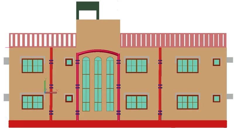
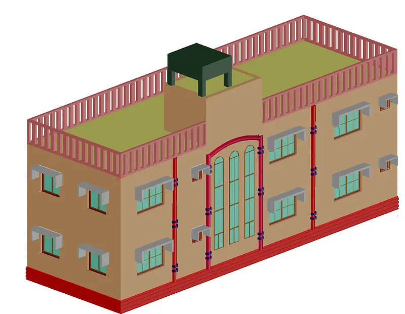
Type RMAT
Go to Autodesk Library
Select Concrete and choose one of the types and add material to document: TRAVERTINE CREAM
Select PLINTH and assign the material to the object.
Press Enter
Type RMAT
Go to Autodesk Library
Select Wall Paint and choose one of the types and add material to document: GLOSSY GOLD
Select OUTER WALLS and assign the material to the object.
Press Enter
Type RMAT
Go to Autodesk Library
Select Wall Paint and choose one of the types and add material to document.: LIGHT BEIGE
Select SHADES and assign the material to the object.
Press Enter
Type RMAT
Go to Autodesk Library
Select PAINT and choose one of the types and add material to document.: PINK
Select INNER WALLS and assign the material to the object.
Press Enter
Type RMAT
Go to Autodesk Library
Select GLASS and choose one of the types and add material to document.: LUMINUOUS CREAM
Select WINDOWS GLASS and assign the material to the object.
Press Enter
Type RMAT
Go to Autodesk Library
Select GLASS and choose one of the types and add material to document.: ETCHED
Select WINDOWS GLASS and assign the material to the object.
Press Enter
Type RMAT
Go to Autodesk Library
Select WALL PAINT and choose one of the types and add material to document.: LIGHT RED
Select PARAPET WALL and assign the material to the object.
Press Enter
Type RMAT
Go to Autodesk Library
Select FLOORING and choose one of the types and add material to document.: LOOP_LIGHT BLUE
Select SLAB and assign the material to the object.
Press Enter
Type RMAT
Go to Autodesk Library
Select WALL PAINT and choose one of the types and add material to document.: CADET BLUE
Select O.H.T and assign the material to the object.
Press Enter
Type RMAT
Go to Autodesk Library
Select WALL PAINT and choose one of the types and add material to document.: VIOLET
Select STAIRCASE and assign the material to the object.
Press Enter
Type RPREF
Render in: window
Choose Render Size: 1920 X 1080 px - FULL HDTV
Name: PROJECT_2
Type RR
Save the file at required location.
RESULT: -
We created 3d model of the Residential Building in 3D modelling.
We applied Material to all the parts of the Building.
We rendered the model and saved the images of the building.