Project 2_Creating a 3D rendered model for a Residential Building in AutoCad
AIM: To create 3 Dimensional rendered model of the residential building.
INTRODUCTION:
This is the residential building plan which has been done for project 1. Here i am doing 3D view of it by assuming the required dimensions.
ASSUMPTION:
Wall height= 9'9"
Exterior wall thickness= 9"
Interior wall thickness= 4"
Door:
- D1= 4'-11" X 6'-10"
- D2= 3'-3" X 6'-10"
- D3= 3'-0" X 6'-10"
Window:
- W1=4'-11" x 3'-3"
- W2=3'-3" x 3'-3"
- W3=3'-2" x 3'-3"
- V=2'-0" x 2'-0"
PROCEDURE:
- Open cad application in the pc and set all the limits required.
- Set the units as required for drawing. Set units in Engineering and scale in Inches.
- Keep ortho on for easily drawing lines in right angles.
- Start the drawing with the mentioned plot size and orientation.
- Select construction line and draw the outer line of the wall.
- Select offset command and carry on the drawing as given in drawing.
- The each house is different in size, shape and dimensions.
- After selecting the house take wall thickness of outer as 9" and inner as 4" where ever required.
- So the respective wall thickness wherever shown in plan.
- After completing all the walls offset.
- Select trim command and trim off the extra lines and make a good corner.
- While trimming the lines watch the given plan again and again for accurate drawing.
- Now do the staircase part using given size and show the tread with 9".
- Next show the doors wherever needed with respective sizes.
- Select the size with respect to the ease of use.
- Use line command to draw the lines of door.
- Using trim command remove the unwanted lines.
- Once the doors are done now go with windows.
- Select the window size with respect to room size and utility.
- Keep the window in the centre of each room walls.
- Now here we have to extrude the wall and window so make a boundary using boundary command.
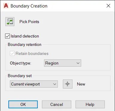
- The above dialogue box will appear. Select the region option in Object type.
- After all the options select the Pick points option.
- In drawing select the wall inner lines and a Region will appear.
- To check the region goes to shaded visual style.
- While doing region of wall don't select the window part let it be unregioned.
- Now go to South West view and select the extrude command.
- Select the region to be extruded and select the direction.
- Then type the height as mentioned.
- The extrude is only done till the bottom of slab.
- There is a rectangle in the plan for window, so extrude it till sill level.
- Select ucs option and change the X and Y axis direction so that we can draw a rectangle in the wall top.
- Now extrude the rectangle till the lintel bottom.
- Select the UNION command and select the three parts of wall and combine it.
- Go to shades and check the drawing.
- Come back to wireframe visual and draw the Chajja using line command.
- Make the region of the Chajja using boundary command.
- Now extrude it as required width.
- Now we have to do the window panels and frames.
- Change the UCS as required and draw the rectangle.
- Select the offset command and show the thickness.
- Create a REGION using boundary command as done before.
- Here we have to subtract the region that intersects with the other panels.
- Select subtract and select the region from which the subtractions to be done.
- Next select the region which has to be subtracted then press entre the subtractions will be done.
- Then do the extraction of each panel as required. Then move inside or outside as required.
- Select copy command and place it in the 3D view where ever required.
- Now all the structure part is done. The 3D model is ready now all the material as required.
- Select the Material browser a dialogue box will appear.
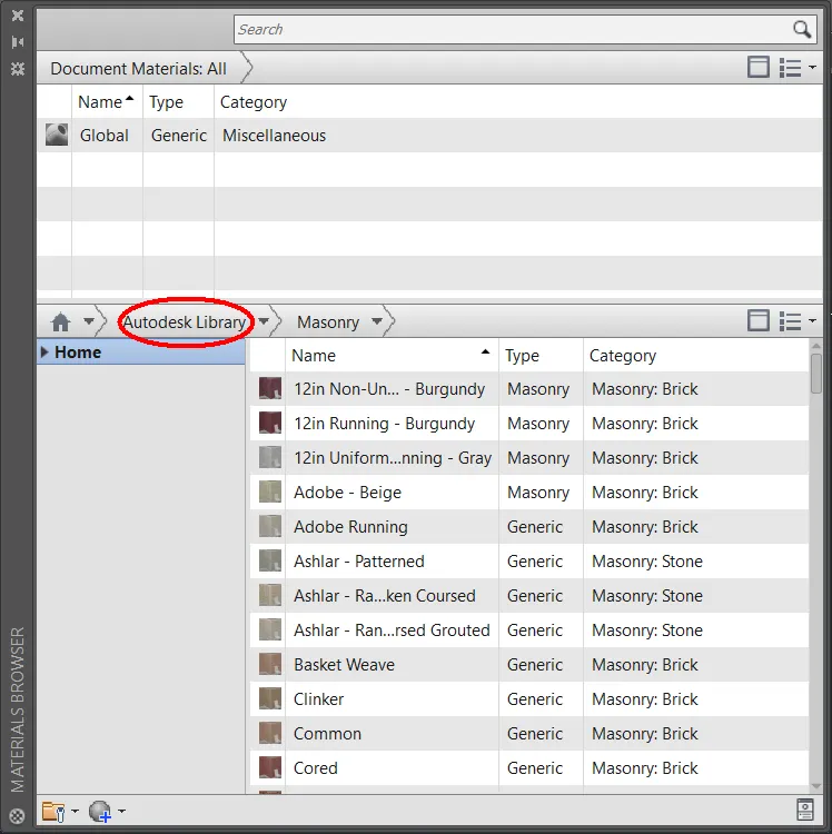
- Go to Autodesk Library and another drop manual will appear.
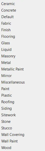
- From the above select the type of material or object you want.
- Then the several material and pattern option dialogue will open as shown below for concrete.
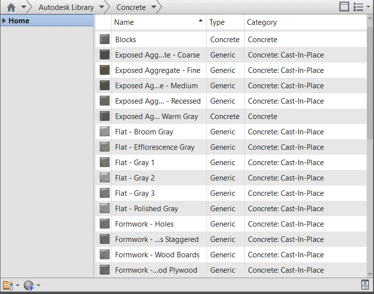
- Scroll down till end just watch all the material and select anyone.
- By double clicking the any material we will get a dialogue box where we can clearly see the properties of material. As shown below
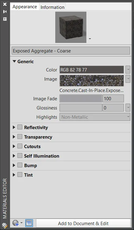
- Here you can also create the costume material.
- Once the material is finalized then do as mentioned below

- Add that material to document there we can edit it even better as required.
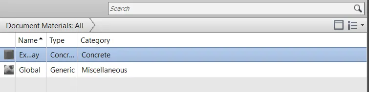
- Then it will appear like shown above. Do all the changes or editing as required.
- Now in background select the object or structure where the material has to be applied.
- Then go back to the material browser.
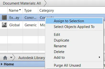
- Right click on the material that has to be applied. Then a dialogue box will appear there select the Assign to Selection option.
- Then we can see the material is applied. Go to shaded view the material can be easily examined.
- Change the scale as required making it clearer.
- Apply the material for all the other structure by selecting different material.
- Carry the same procedure as mentioned above.
- Now we have to create the camera view for better picture.
- Draw a circle or anything that can be extruded.
- It is done for prefect placing of the camera.
- Select the create camera option.
- Select the point where the camera has to be placed. Then select the point in the drawing so the view can be fixed.
- The height is done using the solid object so now select the lens and other things if required.
- Then click the camera to see the preview to check the placement of the camera.
- The below dialogue box will appear
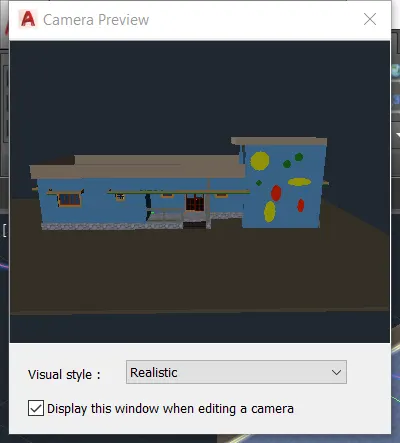
- Here we can also change the visual style as required.
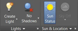
- Once the camera is fixed then does the other editing like Light, Shades and Sunlight.
- Here we can also edit the exposure and the other things.
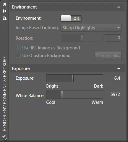
- Go to Sun light option and this box will appear where we can add background and edit the light exposure etc.
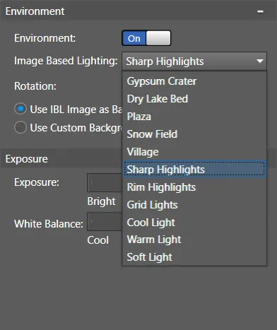
- Using the above box select the type of floor and background required.
- After all the editing and put-ons are done now do the rendering for a clear and clarity view.
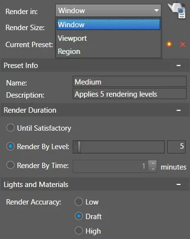
- Here we have several options to do the rendering as shown above.
- If we select the window option then we get to select the size and everything.
- Here we can select the rendering levels.
- Time can be allotted. Accuracy can be settled. Once all the setting is done then select render button.
- The dialogue box will appear after rendering that shows the status and time required.
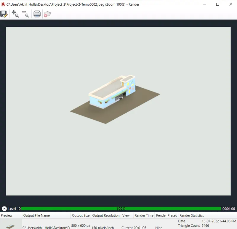
- It shows the final outcome. There are many options to do the rendering select as per our convenience.
- Then the rendered structure is viewed in the camera and the view is saved as required.
- The render can be done using the costume picture also if required.
- Can also be plotted in the layout using the Viewport command by selecting the camera as the view.
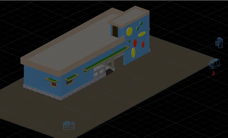
RESULT:
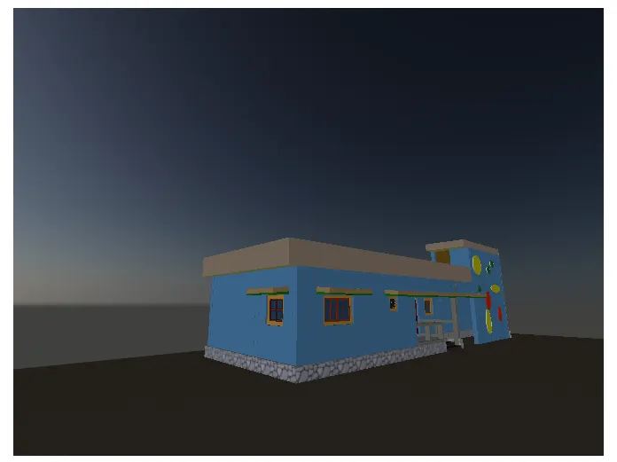
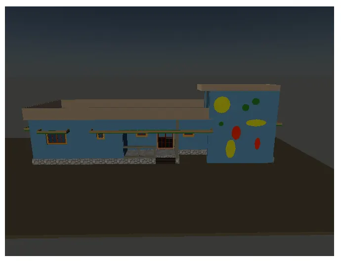
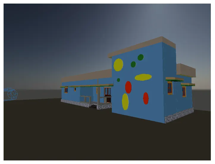
Note: The above 3 pictures are captured using different camera views, Below the pdf have been attached which has more clarity.