Project 2_Creating a 3D rendered model for a Residential Building in AutoCad
AIM:
To draw a 3-dimensional model of a residential building of dimensions 60' x 20' with the following drawings
INTRODUCTION:
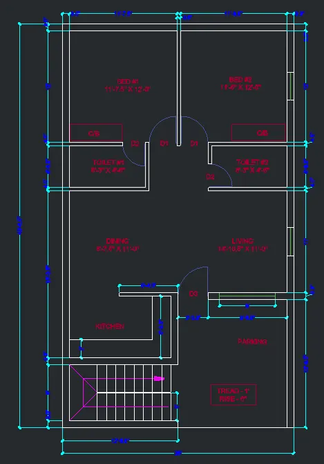
The residential building to be drawn with plot dimensions are 44' x 25'.
The floor is designed as a duplex house with stairs outside the home.
The plot is east-facing.
The building is designed with the following rooms
Ground floor great room
Kitchen (open)
On the ground floor two bedrooms
Staircase to the first floor
First-floor great room
On the first floor two bedrooms
Balcony
Staircase to roof
The building is designed with the main door at the north east facing north and the main gate on east north. Initially, layers are created for all the components of the house.
The dimensions of the components of the house are as follows
Walls
The thickness of the main walls is taken as 9" internal wall thickness is taken as 4.5"
Columns and beams
All the columns size are 9" x 12" all the beams size are 9" x 9" rebar specifications
Doors
Doors are three types are used main door (D1) size is 3' x 7' D2 is 2'6" x 7" D3 is 3'3” x 6'
Windows
Windows size is 3' x 4'
Procedure
First, the size of the plot is marked with the help of construction lines after setting the limits and units of the drawing sheet to Architecture type
Construction lines in the horizontal and vertical directions are drawn using the command XL
A corner is created by trimming the bottom and left side of the construction line using the TRIM command
In order to create the outer wall, the OFFSET command is used with a distance of 9". Another offset of 4.5" is created for internal walls.
Create a bedroom of size 10” x 12’2”
Create toilets of sizes 8’ x 4’2’ and 8’ x 4’
Create an open space of size 8’ x 4’
Draw the dining cum kitchen area of size 8’ x 17’4”
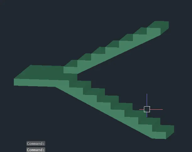
Provide staircase in this area with riser 8.5” and tread 12”
Draw hall of size 18’6” x 14’
Draw another room of size 8’ x 10’6”
Draw porch area of size 10’2” x 17’6”
Create a lawn of size 8’5” x 6’8”
Provide doors of size 3’ using the TRIM command
Using the MTEXT command mention name and dimensions of each unit
To create the first-floor plan copy the entire plan
Erase the toilet, making room size of 10’ x 16’7”
Create a lobby of size 10’6” x 9’4”
Provide a dress and toilet in the hall of sizes 4’10” x 5’4” and 4’10” x 8’
Combine room and porch to make an open terrace
Provide doors of size 3’ using the TRIM command
Using the MTEXT command mention name and dimensions of each unit
Change the workspace setting of AutoCAD from drafting and annotation to 3D modelling.
These commands are used to draw the plan and windows with their dimensions
The region is used to create the region of the plan and wall
The region is used to create the region of the floor
A boundary is used to create the boundary of the region created by picking the points.
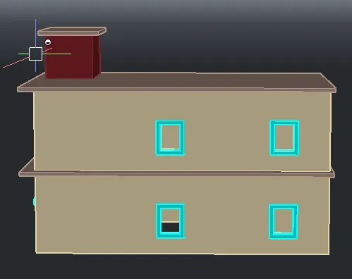
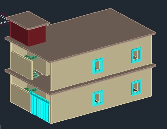
Extrude is used to extrude the walls created at a height of 10’
Extrude is used to extrude the ceiling created at a height of 6"
3DORBIT is used to see the 3D plane in the XZ plane to the XY plane
Extrude is used to extrude the window created at a height of 3’
Assign the material to each component accordingly
RESULT