Project 2_Creating a 3D rendered model for a Residential Building in AutoCad
PROJECT 2
Aim: To create a 3 dimensional model of a residential building with a rendered view.
Introduction: AutoCAD is a 3D CAD software that is used commercially across the world. AutoCAD offers an exclusive range of commands and functions both for 3D and 2D modeling. While working in 2D, the user only cares for the X and Y axis. Whereas, while working with 3D, the user uses all the coordinates, which can even make their work quite easier with some amazing tools. A 3D model can even be represented as a 2D image by using the 3D rendering process which helps the designer to view the model in all directions, and they can make sure that the object created is like the original one.
Procedure:
- Open AutoCad
- Select imperial system and set the units
- Now select Engineering with 0.0" precision
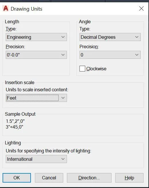
- Set the limits as, lower limit: 0'0.0",0'0.0" and upper limit: 1000'0.0",1000'0.0"
- In the command prompt, type zoom and select all
- In the 3D model, change the view to Top view to create the plan
- Plan ( Ground Plan and First floor Plan) is created with the following rooms sizes
- Living room: 10' * 8'10"
- Dining space: 10' * 8'2"
- Kitchen: 10' * 6'
- Store: 6'6 * 3'6"
- Master bedroom: 11' * 10'
- Toilet (attached to master bedroom): 6'6" * 6'
- Lobby: 12' *6'6"
- Common Toilet: 6' * 6'
- Bedroom 2 : 11' * 10'
- Bedroom 3 : 11' * 10'
- Toilet (attached to master bedroom): 6'6" * 6'
- Common Toilet: 6' * 6'
- Meditation room : 11' * 4'
- Open balcony : 11' * 8'
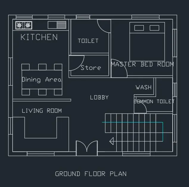
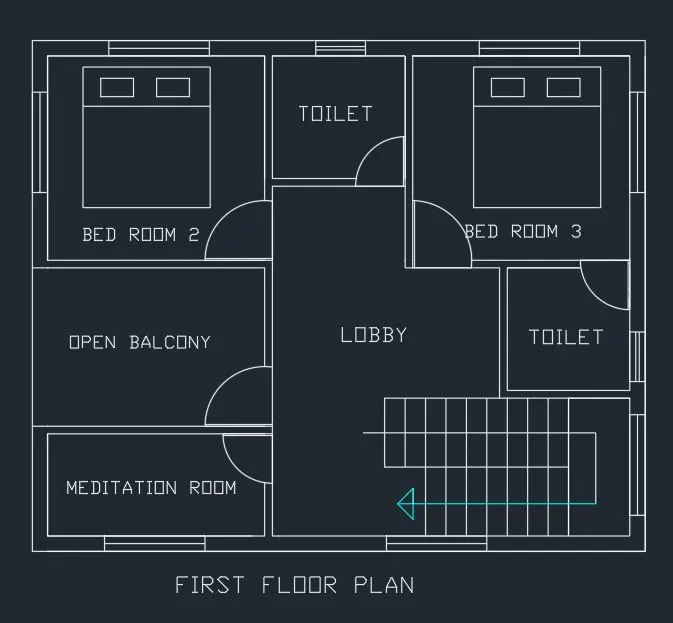
- Extrude the walls at required height using EXTRUDE command
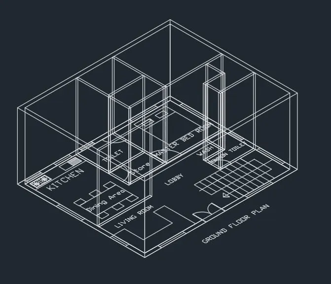
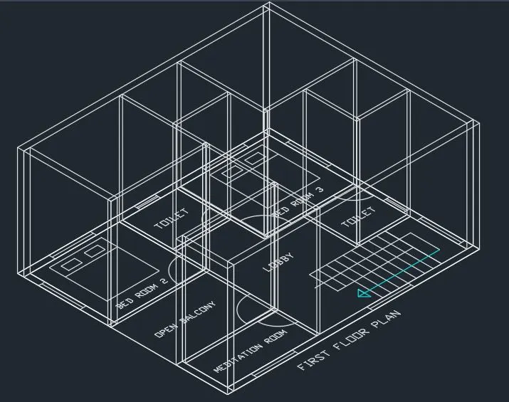
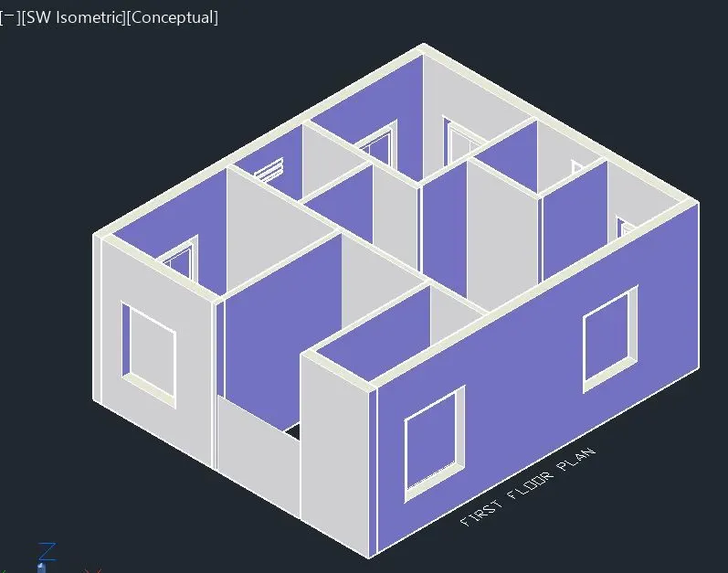
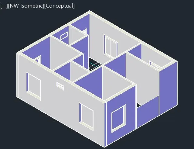
- Now when changing from 2D wireframe to conceptual, we will get the clear idea about the walls we extruded.
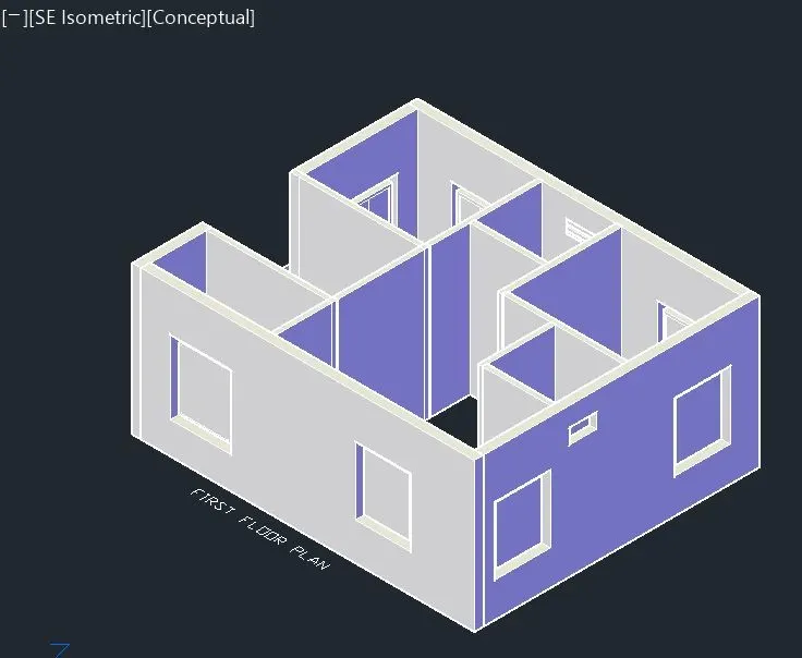
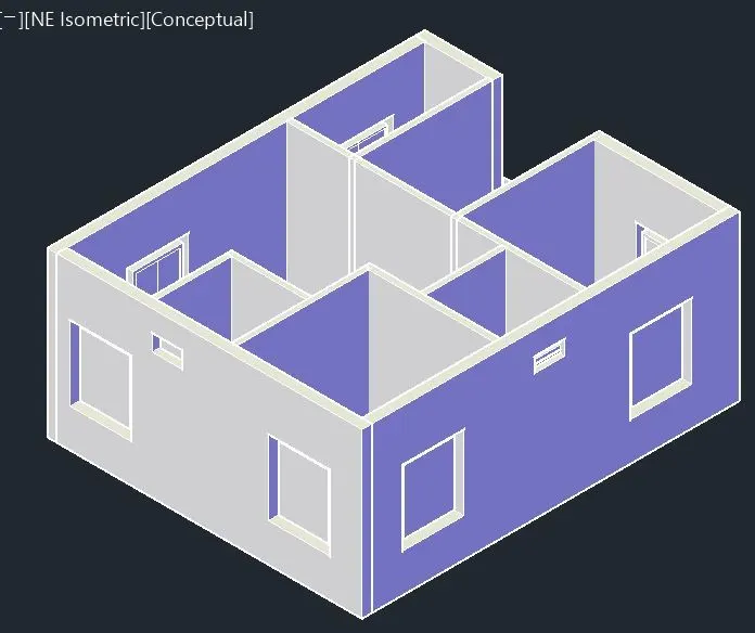
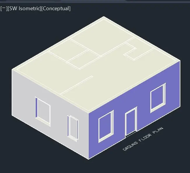
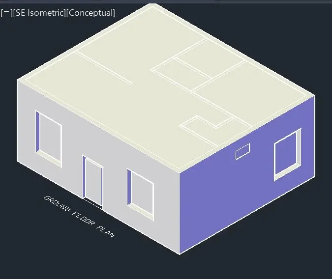
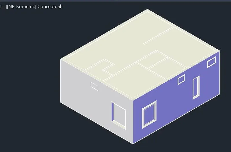
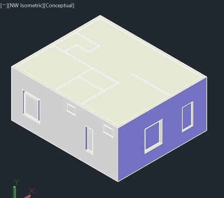
- Next step is do cut the doors, windows and ventilations, for that draw the rectangle of required size. Now extrude the rectangle to the wall thickness.
- Now using the SUBTRACT command, subtract the walls, ventilations and doors from the walls, in both ground floor as well as the first floor.
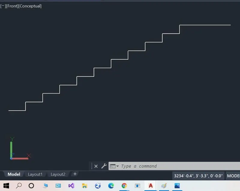
- Select the front view and draw the side vie of the stair, with rise as 6" and tread as 1'. The landing of 3' horizontal and 3' vertical is given.
- For the ground floor, using the front, conceptual view, the floor is drawn.
- Use the REGION command to make the stair to a single object.
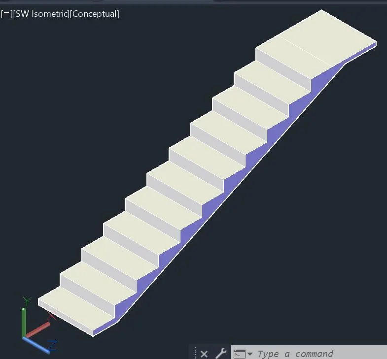
- Select the South west isometric view and extrude the stair to 2'5"
- Hand rails are drawn with the help of line command and extruding it to 2".
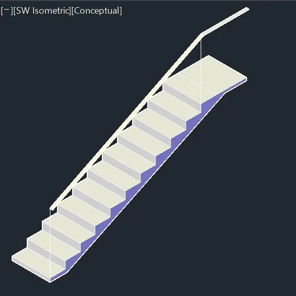
- Using material browser in Visualization, give the suitable material for flooring the tiles and for the hand rail
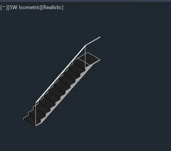
- Now for the stair connection to the first floor, select the front view and draw the stair
- Use REGION command, to make it a single object
- Now in South isometric view, extrude the stair to 2'5"
- Using the line command, hand rail is drawn
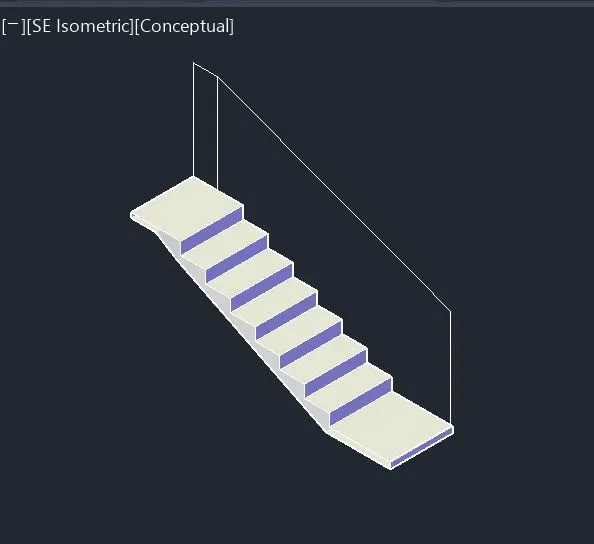
- For getting the thickness of the hand rail, extrude the line drawn for handrail as 2"
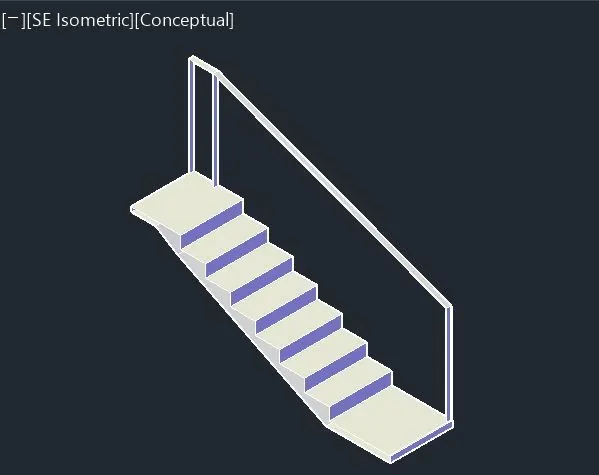
- Using material browser in Visualization, give the suitable material for flooring the tiles and for the hand rail
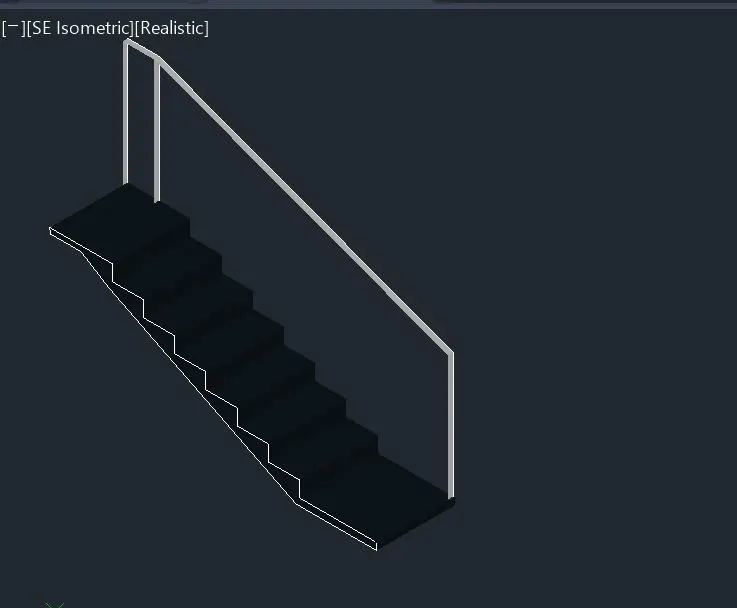
- Now again select the South west isometric view with 2D wireframe, copy the stair for first floor, and move to the first floor plan, as done in the plan
- Select and copy the stairs for the ground floor, at the space alloted for the stairs
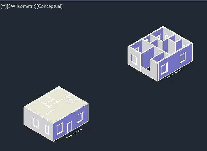
- Copy the the full first floor, and select the base point as one of the edge of the first floor and now move it to the adjusant edge of the ground floor
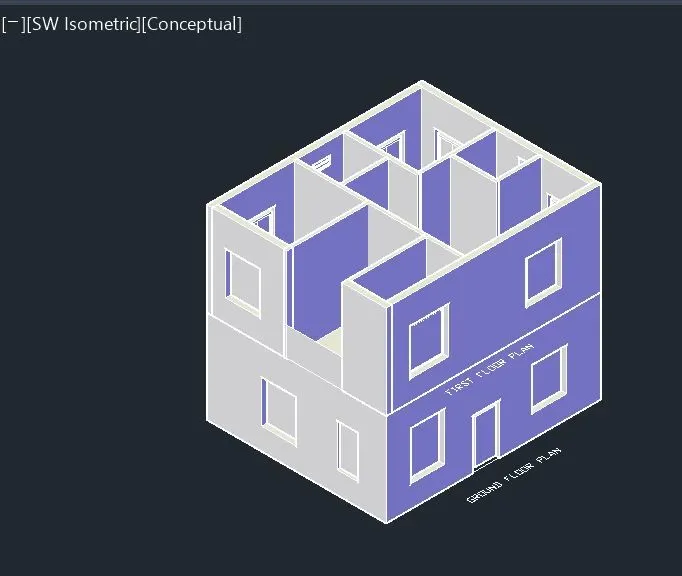
- select the top end of the first floor and draw a rectangle, give an extrude of 6", so that the top slab is made
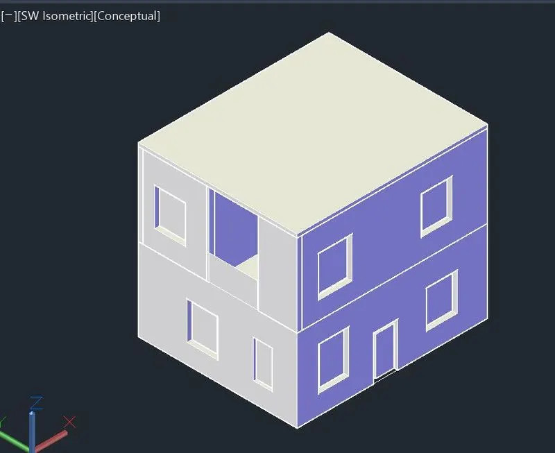
- Now dfraw the parapet with 4" thickness all over the building
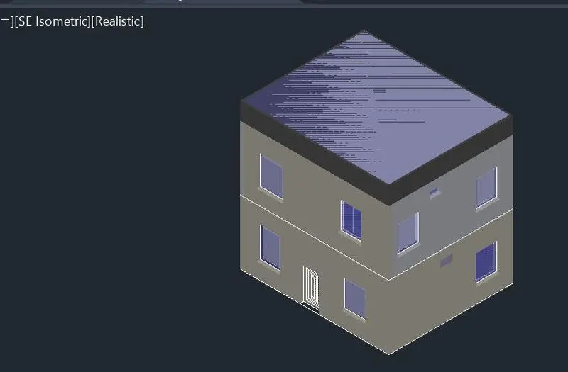
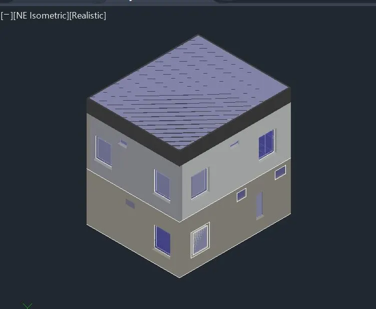
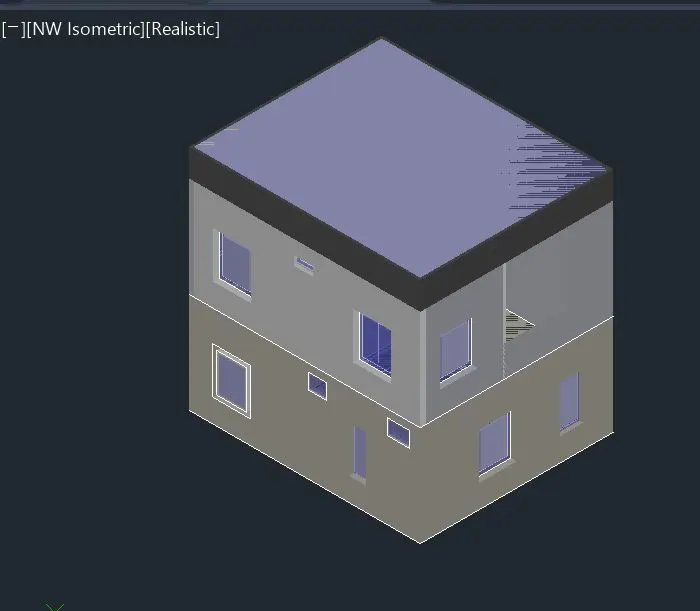
- From the Visualization, select material browser and select the appropriate material,
- select each view and give the material accordingly
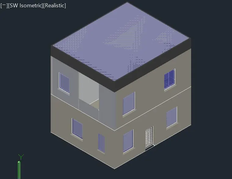 ,
, 
- Draw a base to place the building, and materialise that one too
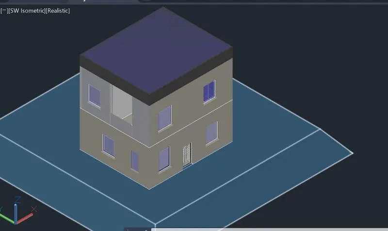
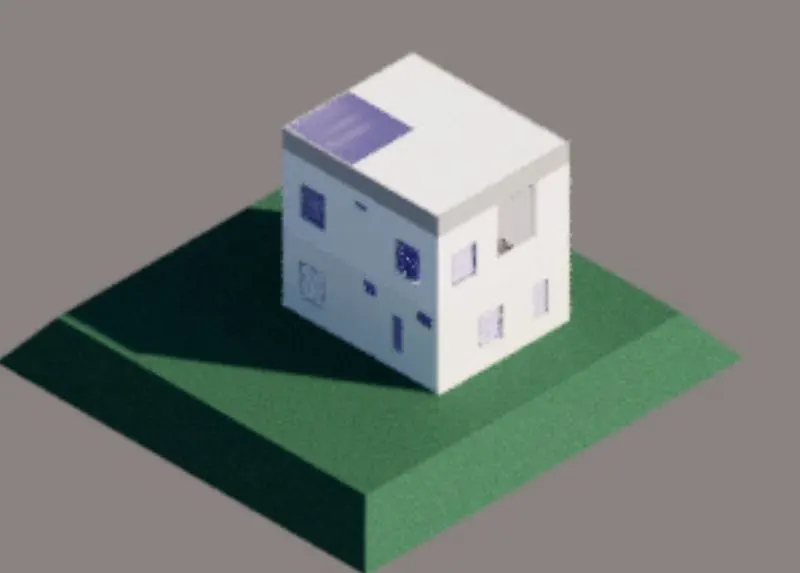
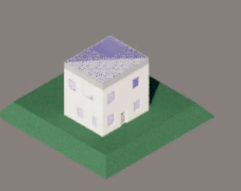
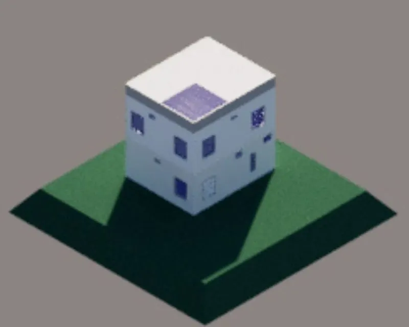
- Now using the Render option in Visualisation, rendering is done.
- Rendered view can be seen in all the direction views
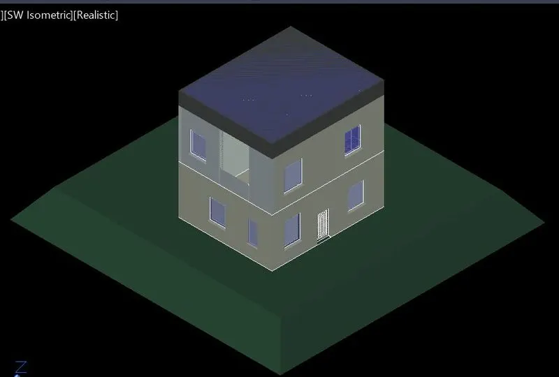
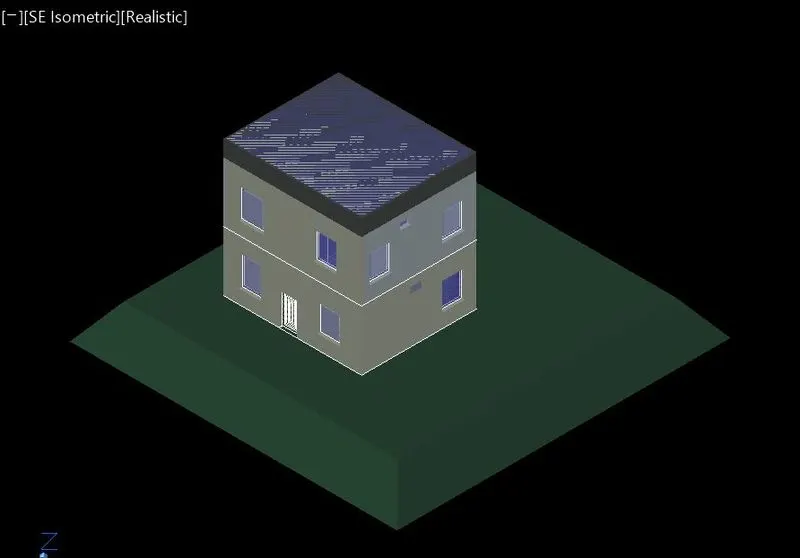
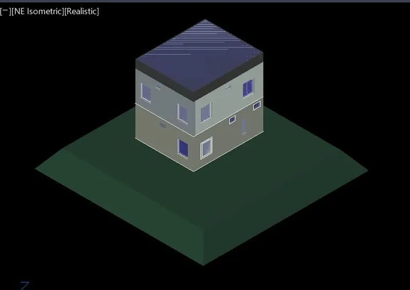
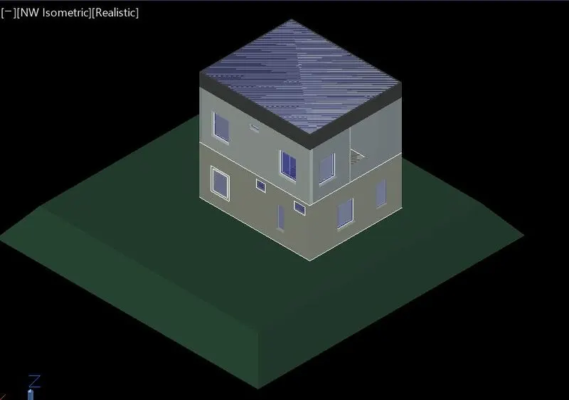
- Now select the Render in cloud option from the Visualization.
- Now reder online
- Thus a clear rendered view can be obtained
RESULT: