Project 2_Creating a 3D rendered model for a Residential Building in AutoCad
Create a 3 dimensional model of the residential building with a rendered view.
AIM:
CREATED A 3D RENDERED MODEL FOR A RESIDENTIAL BUILDING IN AUTOCAD
INTRODUCTION:
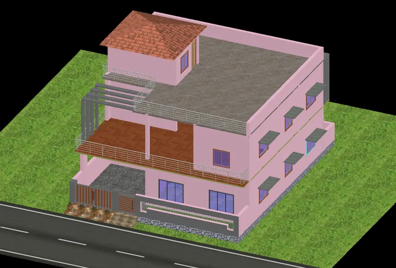
North facing 5BHK residential building created in 3D rendered model by using 2D and 3D tools. The procedure of the drawing is explained in detail with the figure and final result is given
PROCEDURE:
STEP 1) SELECTION OF DRAWING MODEL
- Open AutoCAD software
- Enter command STARTUP for new drawing
- Enter new value for STARTUP 1
- Create NEW file from quick access menu bar
- Click on IMPERIAL (Start from Scratch dialog box)
- Change the workspace in 3D MODELING from status bar (gear icon)
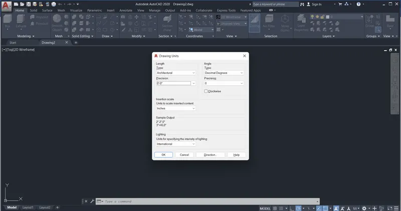
- Set unit, UN enter for unit command
- Type ARCHITECTURAL, Precision 0’-0” and Insertion Scale INCHES
- Set limit, LIM enter for limit command
- Specify lower left corner 0,0 enter
- Specify upper right corner 500’,500’ enter
- Z enter A enter for zoom ALL
STEP 2) ASSIGNED LAYER PROPERTY
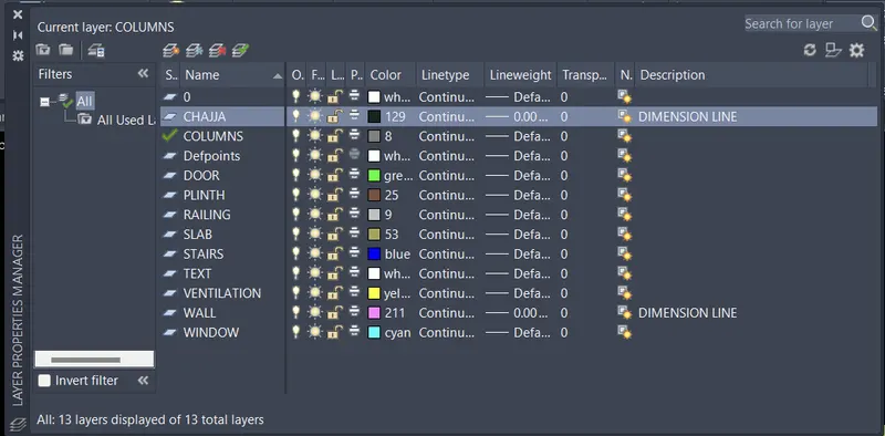
- RIBBON > LAYER PROPERTIES
- CREATE NEW LAYER > RENAME LAYER > WALL, DOOR, TEXT, STAIRS etc.
- Change colour for different layer
- Change the layer according to their object
STEP 3) 2D PLAN
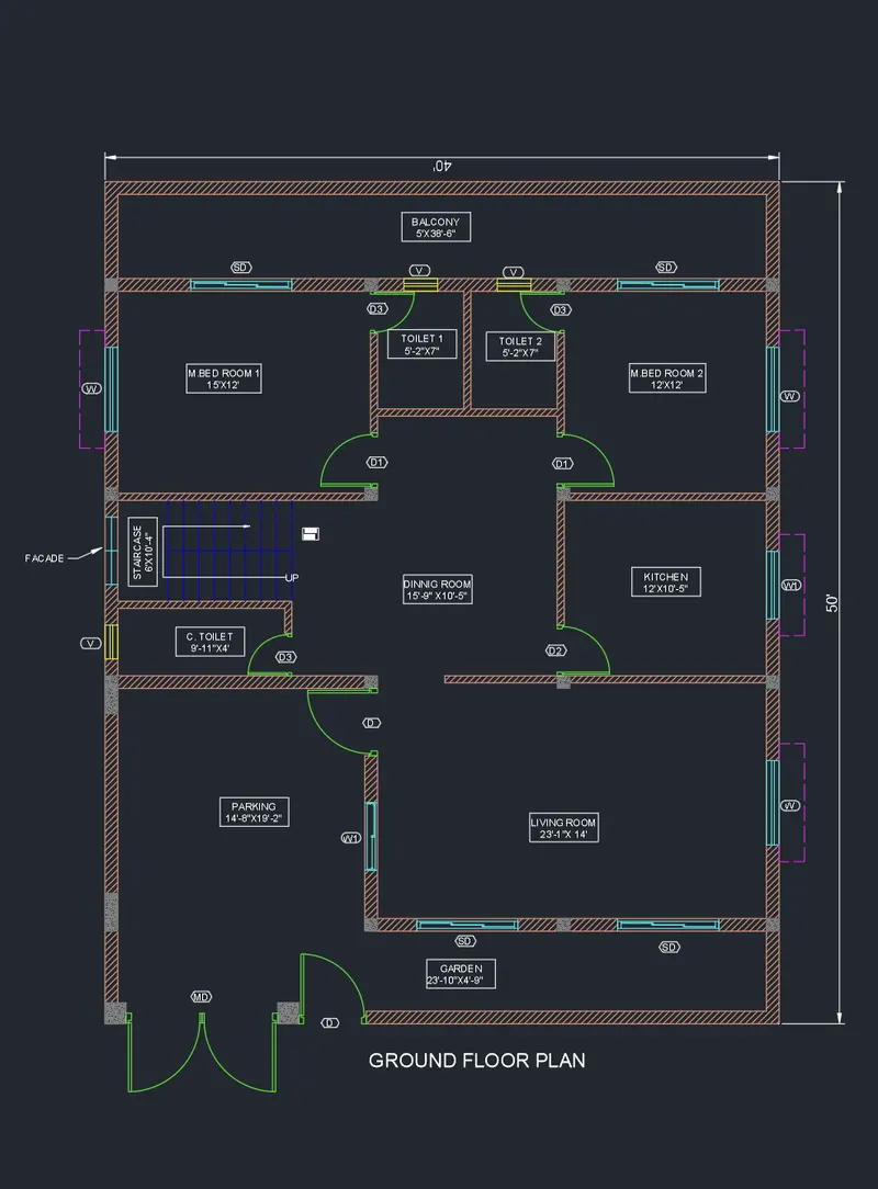
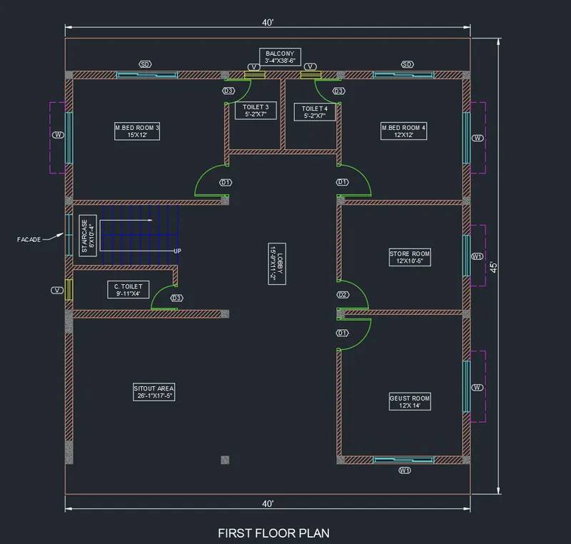
- Created the G+1 North Facing Residential House Plan of the plot size 40’x 50’
- The ground floor plan is 2BHK and first floor plan is 3BHK
- Floor to floor height is 11’-1”
- Thickness of slab and waist slab is 5”
- The size of external wall is 9” and internal wall is 5”
- 14 number of columns provided with the size of 9”x 9”
- 2 number of columns provided with the size of 9”x 27”
- In the ground floor we have created
- 2 master bed rooms with attach balcony
- 1 dining room
- 1 kitchen
- Dog legged stair case where trade 11” and riser 7”
- 1 Common toilet and bath
- 1 living/drawing room
- Car parking
- 4’-9” wide garden/lawn
- There are two gates for the entrance of the house, one is for car parking and another regular access
- All the dimensions of the ground floor are given in the plan below
- In the first-floor plan we have created
- Similarly provided 2 master bed rooms with balcony above the ground floor
- Lobby created above the dining room
- 1 store room above the kitchen
- Stair case
- Common toilet
- 1 guest room
- Sit out area with balcony
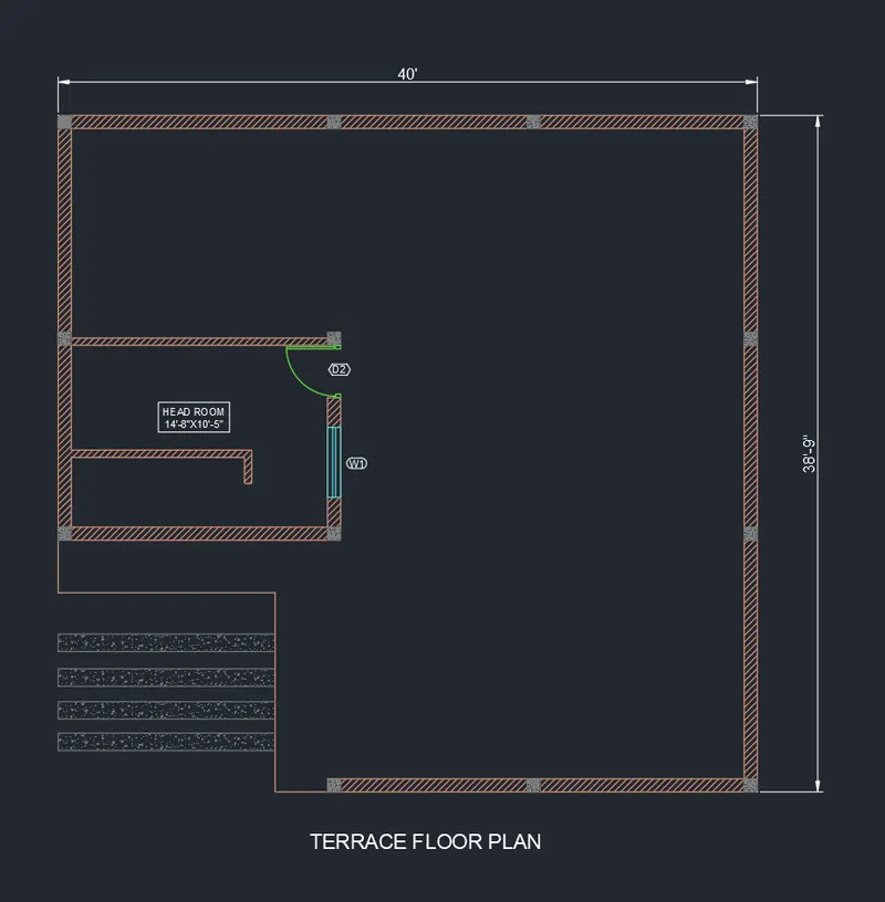
- In the terrace floor created staircase head room and parapet wall
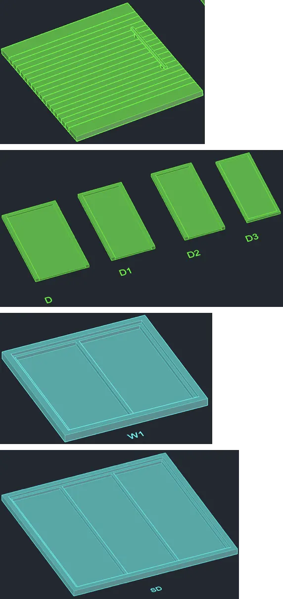
- Size of door, window and ventilation are as
|
SN. NO |
Type |
Size (Width X Height) |
|
1. |
Main Door (MD) |
9’-0” X 4’-6” |
|
2. |
Door (D) |
4’-0” X 6’-6” |
|
3. |
Door1 (D1) |
3’-3” X 6’-6” |
|
4. |
Door2 (D2) |
3’-0” X 6’-6” |
|
5. |
Door3 (D3) |
2’-6” X 6’-0” |
|
6. |
Sliding Door (SD) |
6’-0” X 6’-0” |
|
7. |
Window (W) |
5’-0” X 4’-0” |
|
8. |
Window (W1) |
4’-0” X 4’-0” |
|
9. |
Ventilation (V) |
2’-0” X 2’-0” |
STEP 4) 3D VIEW FOR GROUND FLOOR
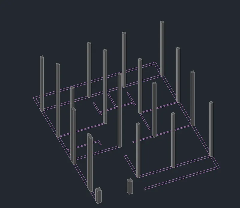
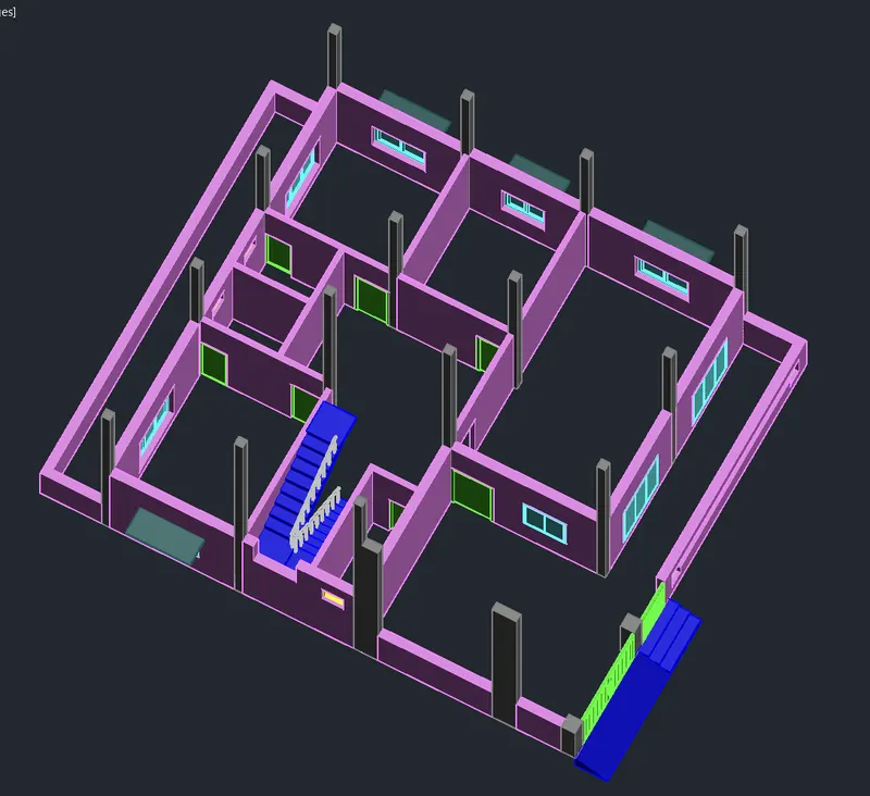
COLUMN CREATE
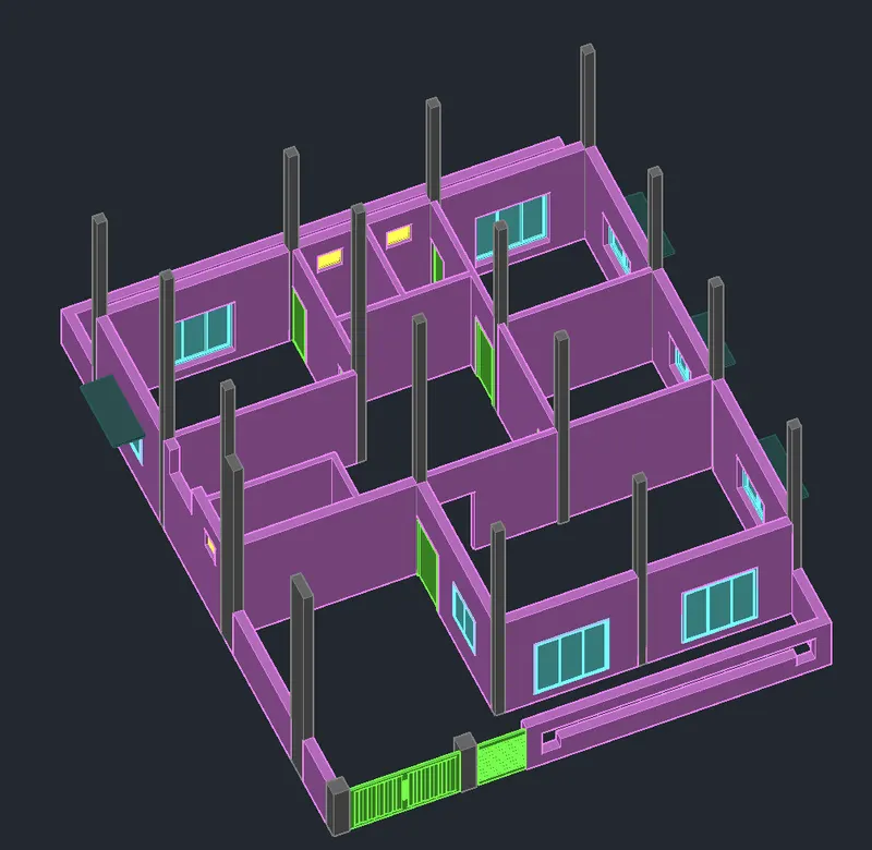
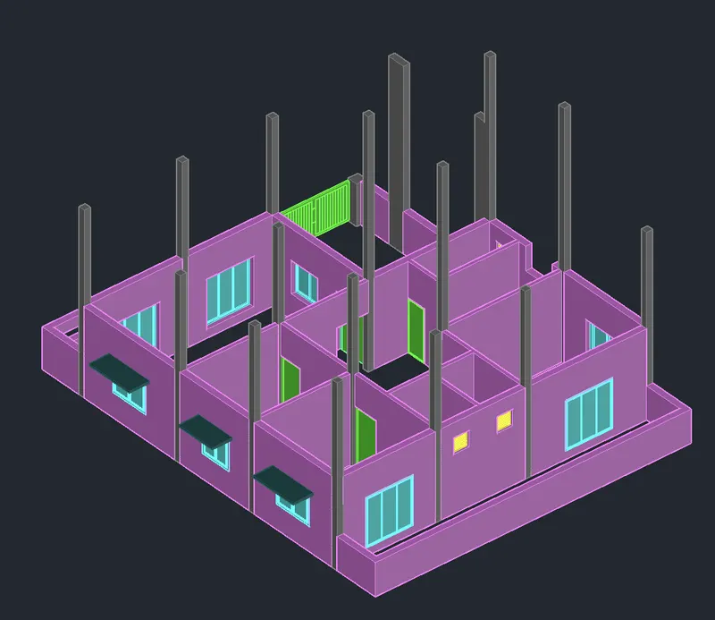
- Make a COPY of ground floor plan
- Change the view as SW ISOMETRIC and visual style as SHADED WITH EDGES
- ERASE the door, window and ventilation lines in plan
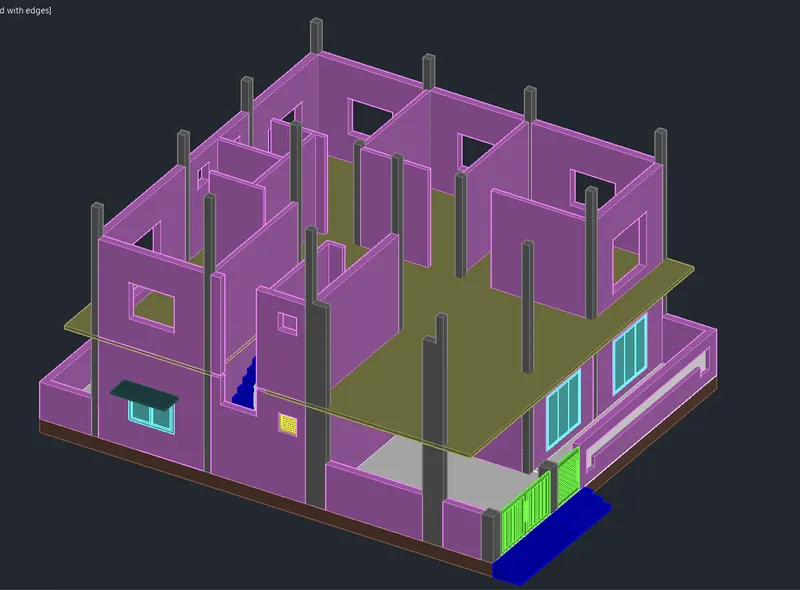
- Using PRESSPULL command to create columns up to terrace level
- Entrance gate column created at 5’ height using PRESSPULL command
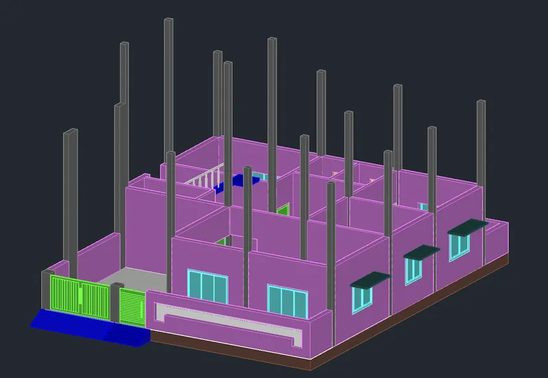
WALL CREATED
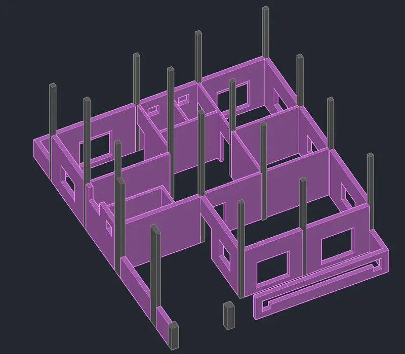
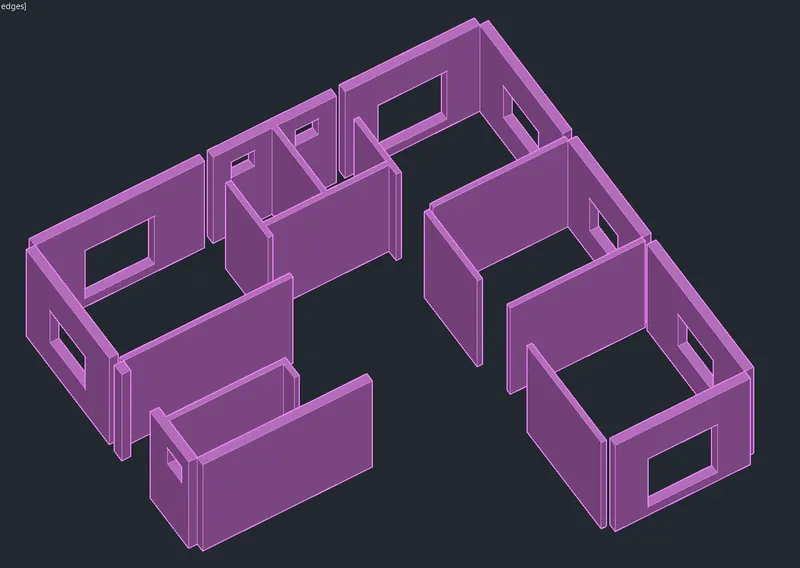
- Wall created by the help of PRESSPULL command up to slab bottom and sill level of the window and ventilation
- All Balcony wall PRESSPULL up to 5’ height
- COPY the window wall from the top and place to slab bottom
- PRESSPULL copied wall in negative Z direction at require size for window
- For door, create a door size of RECTANGLES then PRESSPULL at required height after that place the wall at bottom of slab
- Change the view as FRONT
- Using UCS FACE command in the front side balcony wall create polyline
- PRESSPULL command use to catch the polyline region and pull in negative direction to remove the particular area of the wall
- After creating the walls make union with the help of UNION command
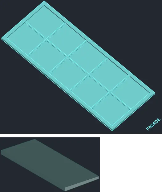
DOOR, WINDOW, VENTILATION AND CHAJJA
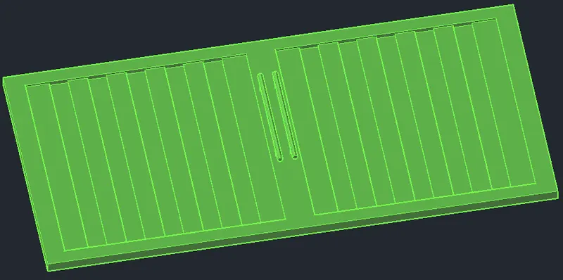
- Created doors, window, ventilation façade and chajja in TOP PLANE with the help of line, rectangle, offset, copy, move, trim, extend and mirror command
- Change the view as isometric
- Use PRESSPULL command to create door, window, ventilation frame at a height for 3D model
- Using 3DROTATE command to rotate the objects
- COPY to place with their respective location
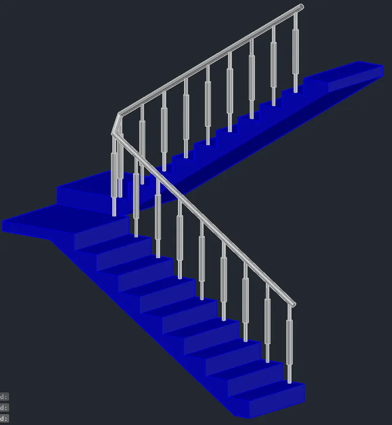
STAIRCASE, RAMP
- Create a section of staircase
- PRESSPULL command used to give a height
- Balustrade create with the help of circle then PRESSPULL for height
- copy balustrade to place each step
- Using 3DPOLY command to create a continue line at the top end of the balustrade
- SWEEP the line with circle for creating circular handrail
- After created 3D model of staircase, place at required location
- For ramp, create a tringle with the help of line command
- PRESSPULL the triangle and 3drotate command to rotate parallel to the main door
- MOVE command used to place at the location
- Similarly, create outside steps for entrance
SLAB
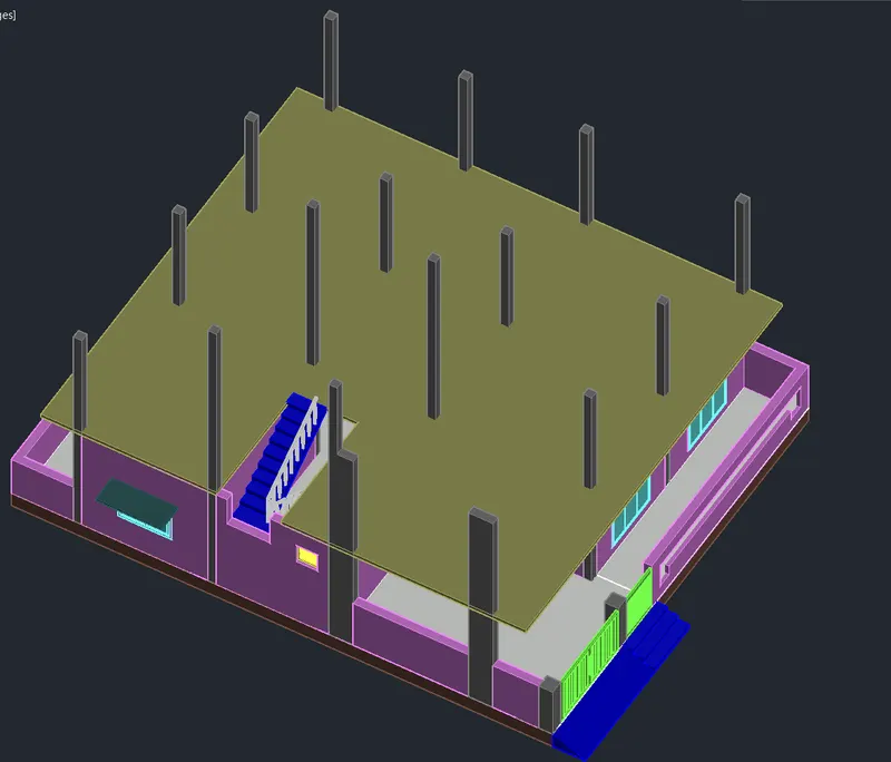
- For grade slab, change the view as TOP
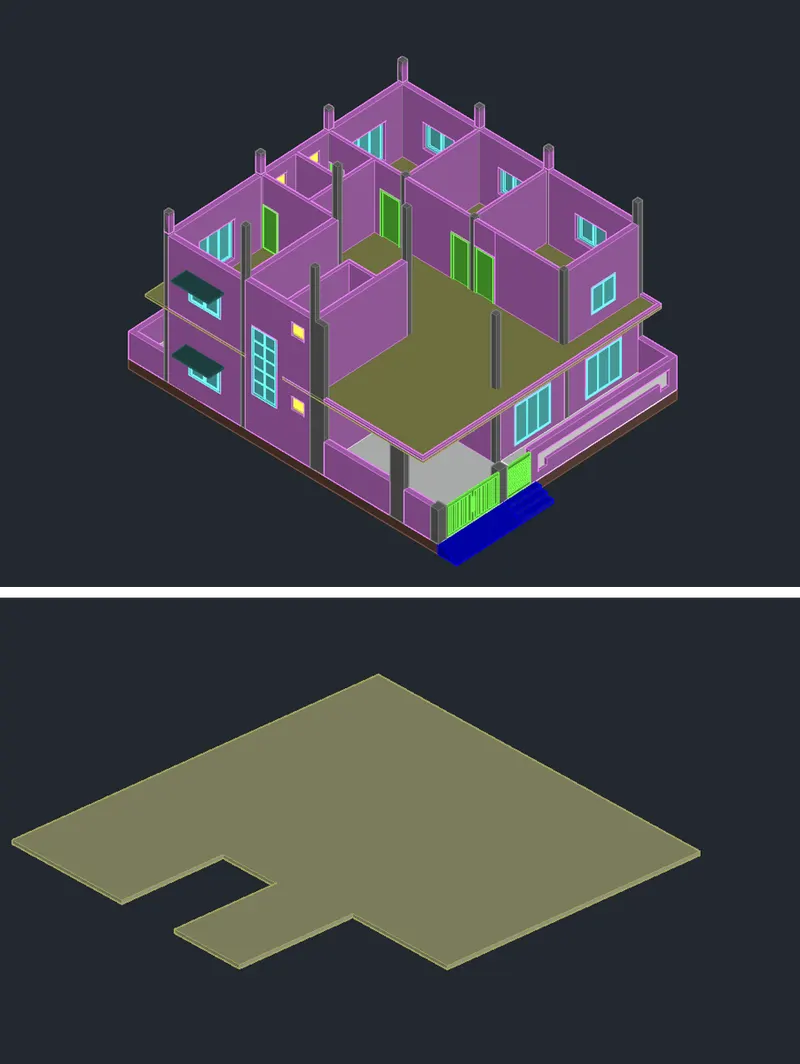
- Using BOX tool command create rectangle at the original ground floor plan and give the slab thickness as 18”
- Move the created slab at the bottom of walls
- Similarly, 5” thick slab created for first floor level
STEP 5) 3D VIEW FOR FIRST FLOOR AND TERRACE
- Followed the similar procedures for first floor and terrace
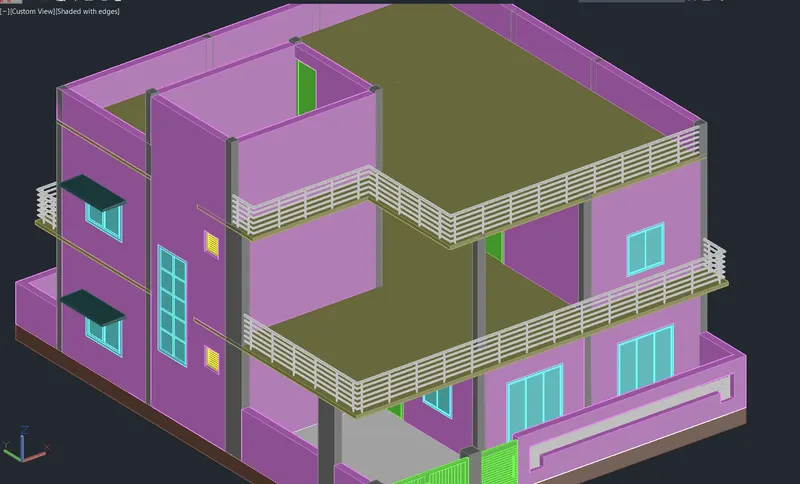
- First floor walls created above the first-floor plan
- Similarly, create head room wall
- UNION command used to union the ground, first and headroom walls
- COPY door, window, ventilation, chajja from ground floor and place to the first floor
- Slab create above the terrace floor plan and place on the first-floor walls
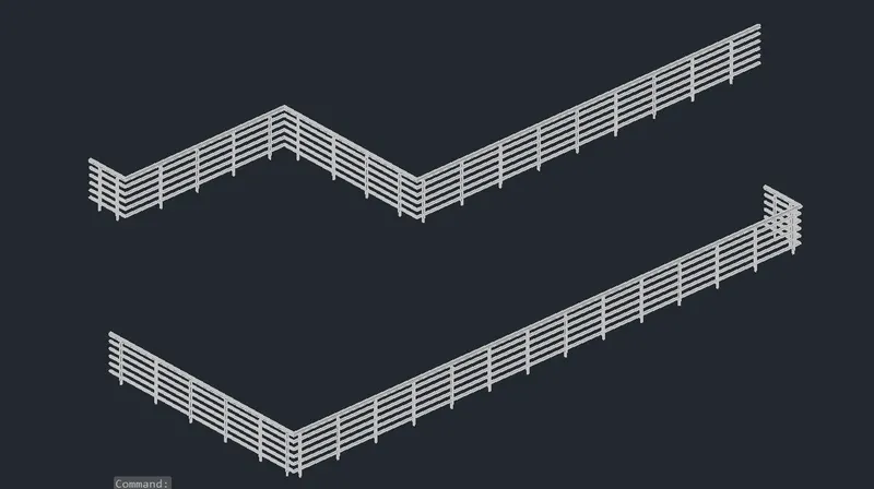
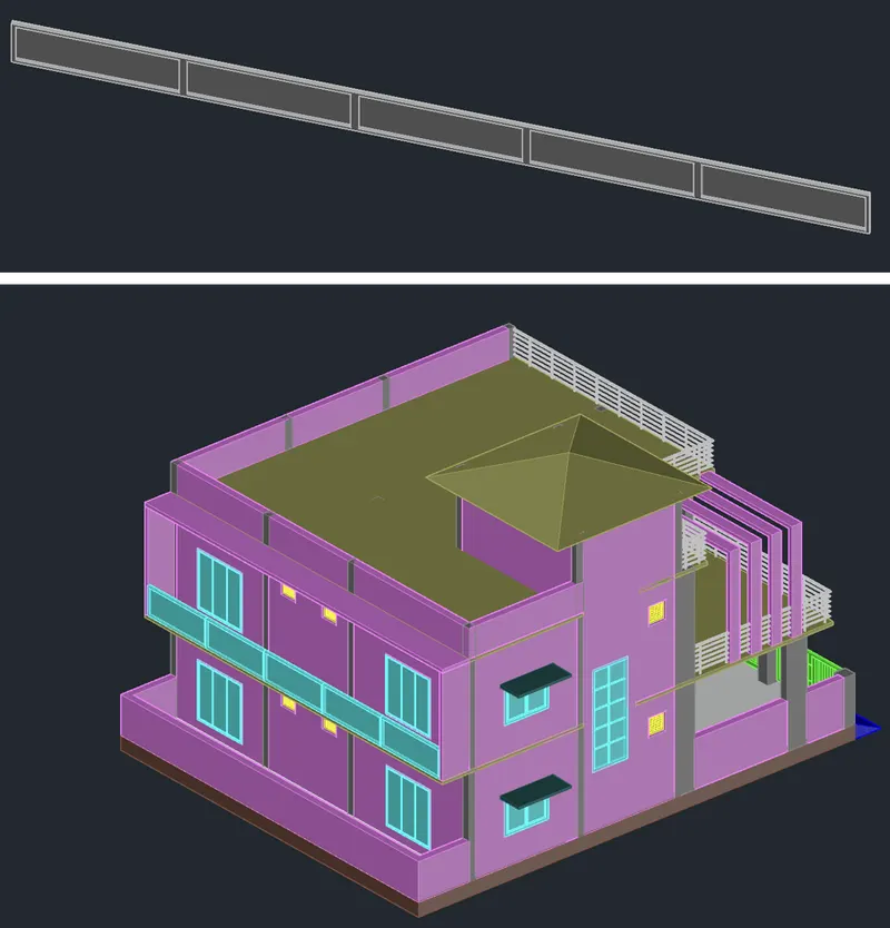
- Create balcony railing for terrace and first floor (front and back), place the railing at location
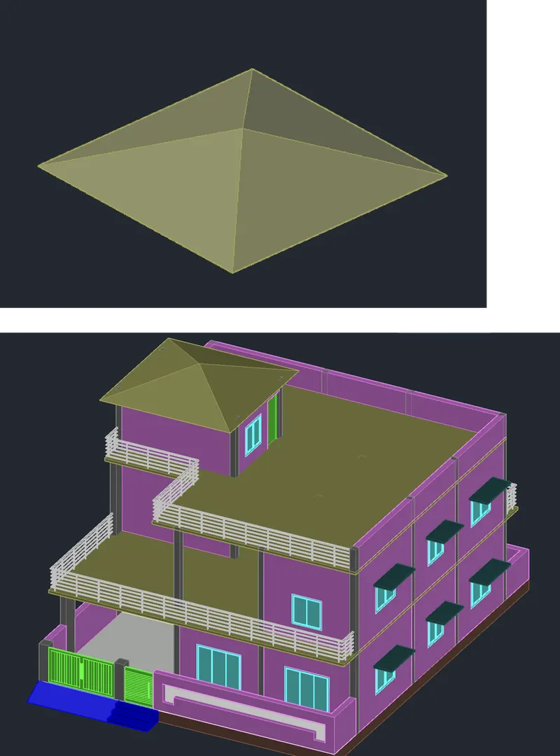
- Create pyramid slab for head room of the staircase
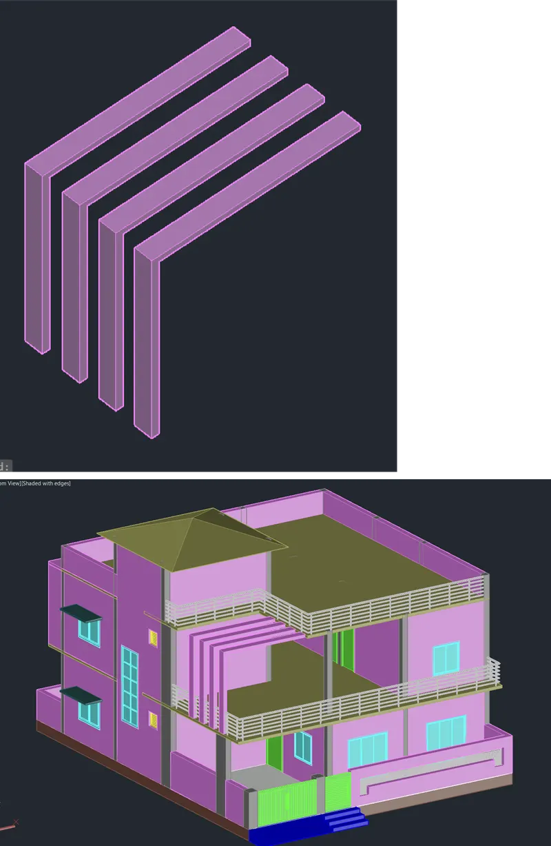
- Create exterior pillars
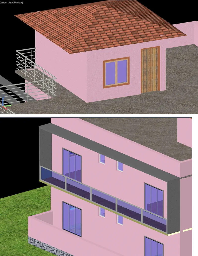
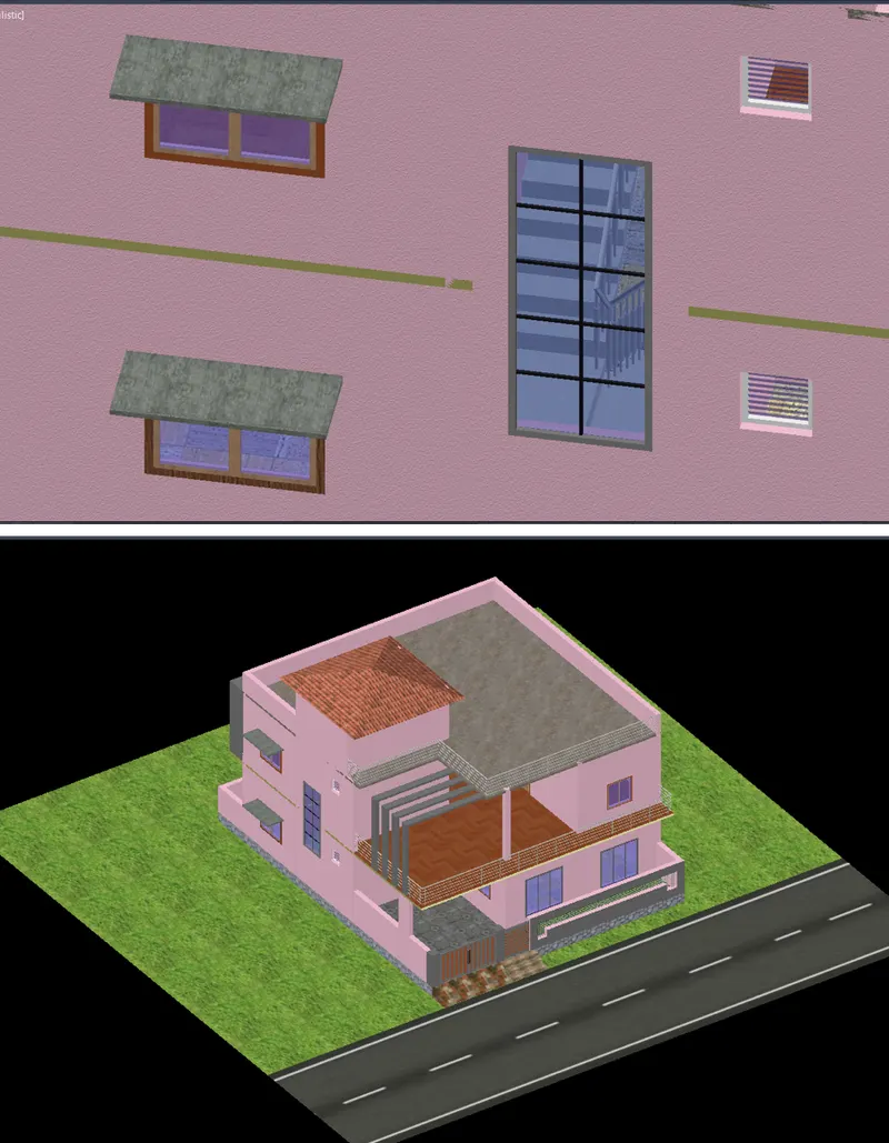
STEP 6) MATERIALS APPLIED IN BUILDING
- Change the view as TOP
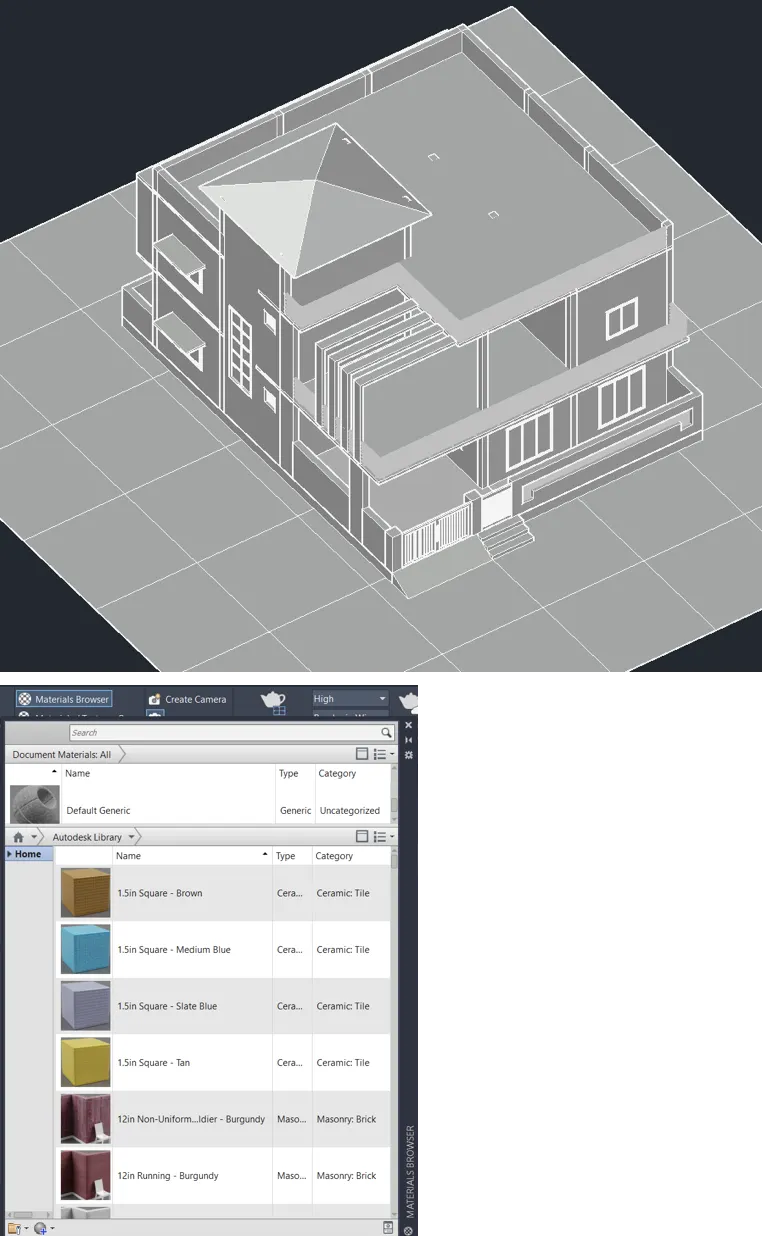
- Using PLANESURF command to create a plane surface
- Change the visual style as SHADED WITH EDGES (its help to assign the material property)
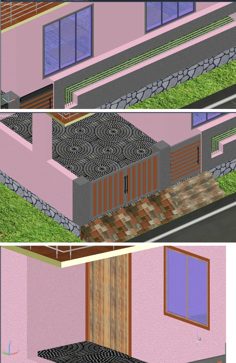
- Check the material in REALISTIC visual style
- Using MAT command for material list or go to VISUALIZATION TAB
- Using different material for different member
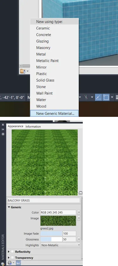
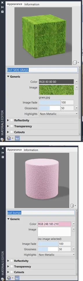
- Create some new material to decorate the building
- For road and grass material download the pictures and attach in default generic material
- Using MATERIAL MAPPING tool to set scale of the material
STEP 7) RENDER THE 3D MODEL OF THE BUILDING
- After applying the material
- Change the view as TOP from view control
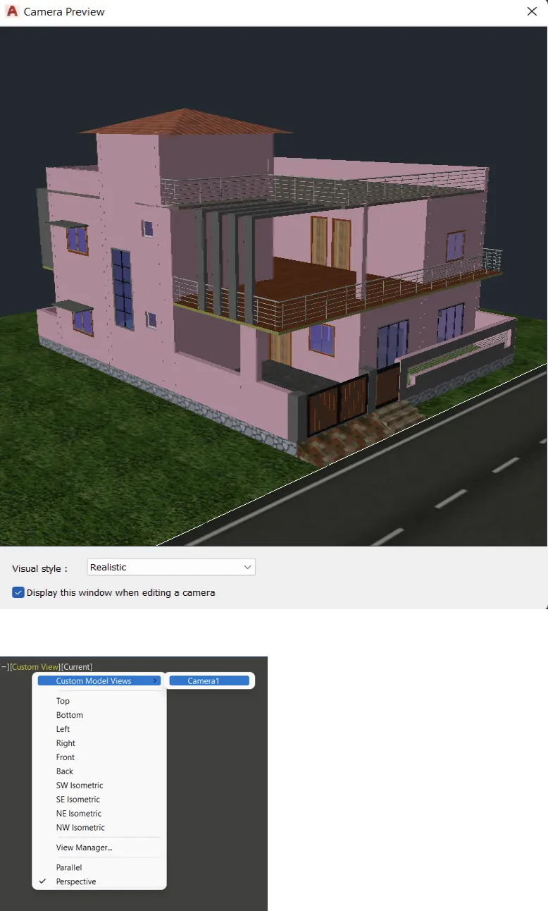
- Create cameras for render from the CAMERA tool in VISUALIZATION tab
- Set camera in 4 isometric views as SW, SE, NE, NW
- Adjust the camera and select REALISTIC visual style in camera preview dialog box
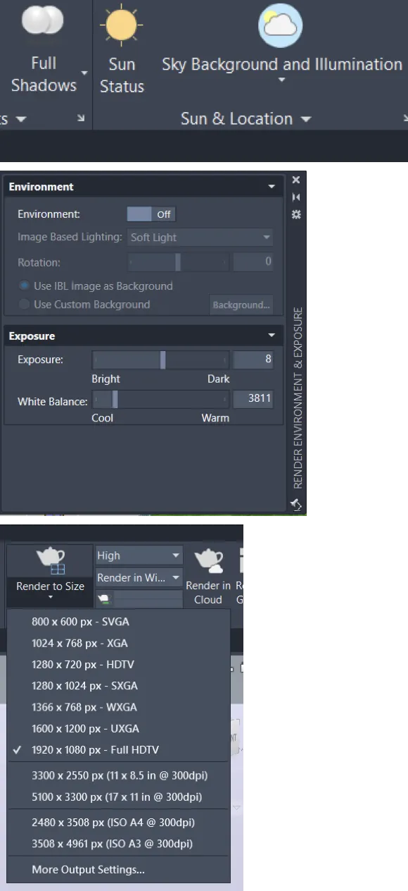
- Select Sky Background and Illumination from SUN AND LOCATION tool
- Select Full Shadows from LIGHT tool
- Adjust environment & exposure from the Render drop down tool
- Select the size and quality from RENDER tool
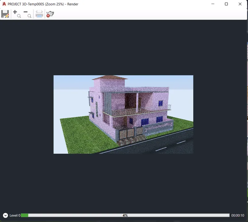
- After that one-by-one RENDER the view
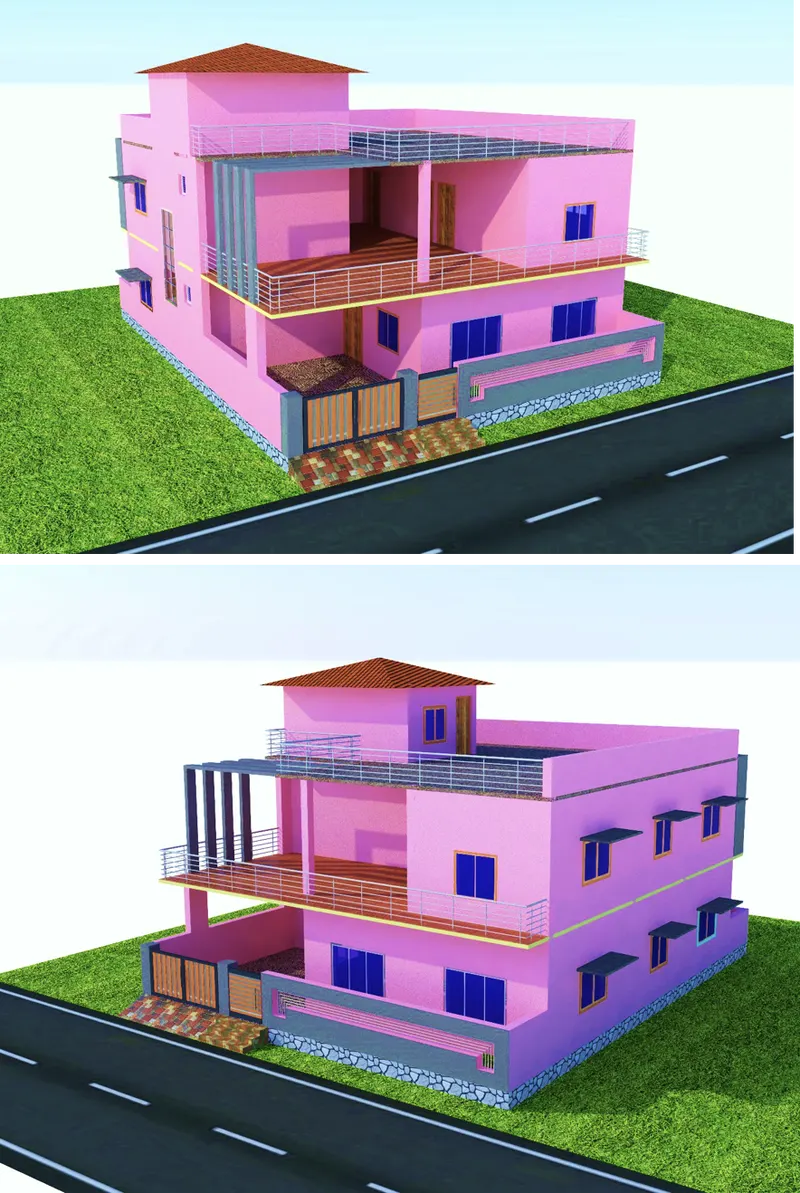
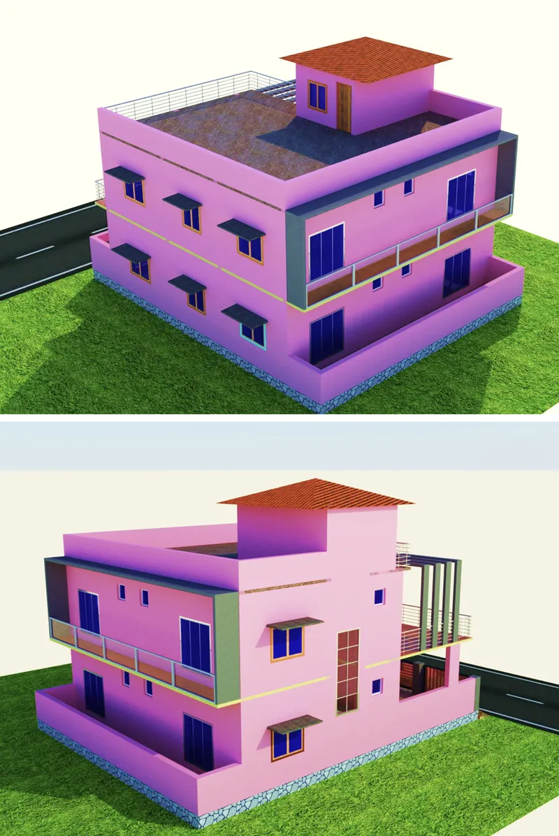
RESULT:
following above procedures steps to be obtain the final result of 3D rendered model
- Vishwa.M Mvery nice keep going
- Rahul Prajapatithanks @vishwa