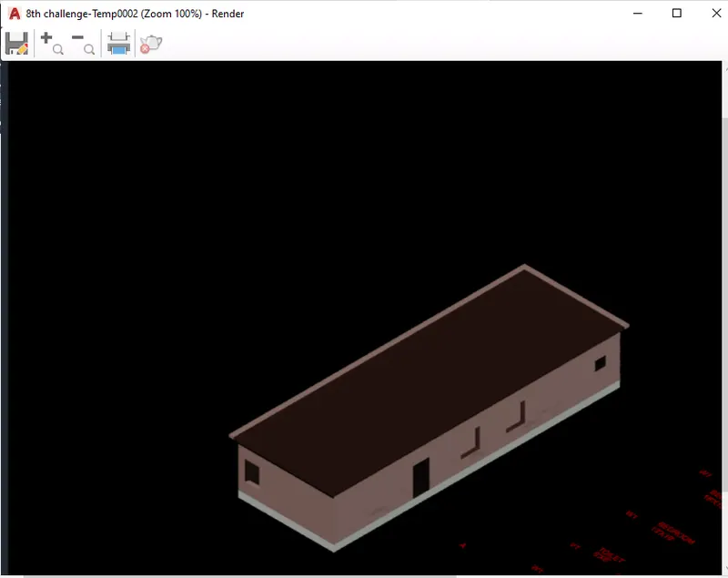
Project 2_Creating a 3D rendered model for a Residential Building in AutoCad
Aim: To create three dimensional residential building with a rendered view using AutoCAD.
Introduction:
AutoCAD is a Computer Aided design software that arichitects, engineers and constructional professionals depend on to create two dimensional and three dimensional drawings
Objectives:
To create Plan using AutoCAD.
To create 3D model of plan using AutoCAD.
To render the created 3D model using AutoCAD.
Procedure:
Plan:
Type "units" in the command prompt and press enter.
Select "Architectural" as unit type.
Then select "inches" as insertion scale and click ok.
Type "limits" in the command prompt and press enter.
Select "off" in the command prompt.
Select line tool from ribbon tab.
Draw a vertical line.
Press esc.
Again select line tool and draw a horizontal line from centre point of previously created vertical line.
Press esc.
Select line tool from ribbon tab.
Specify the starting point as (0,0) in the command prompt and press enter.
Specify the next point as (0,60') in the command prompt and press enter.
Press esc.
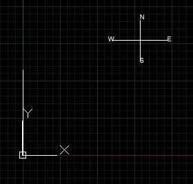
Select the line tool from ribbon tab.
Specify the starting point as (0,60') in the command prompt and press enter.
Specify the next point as (@20',0) in the command prompt and press enter.
Specify the next point as (@0,-60) in the command prompt and press enter.
Specify the next point as (@-20',0) in the command prompt and press enter.
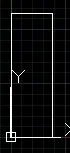
Type "offset" in the command prompt and press enter.
Specify the offset distance as 9" and press enter.
Select all the lines to offset.
Press esc.
Type "trim" in the command prompt and press enter.
Select the intersecting lines to trim.
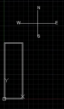
Select line tool from ribbon tab.
Specify the starting point as (9",9") in the commaand prompt.
Specify the next point as (@0,10') in the command prompt and press enter.
Specify the next point as (@8',0) in the command prompt and press enter.
Specify the next point as (@0,-10') in the command prompt and press enter.
Press esc.
Type "offset" in the command prompt and press enter.
Specify the offset distance as 4.5" and press enter.
Select the previously created lines to offset.
Press esc.
Select line tool from ribbon tab.
Specify the starting point as (0,45') in the commaand prompt.
Specify the next point as (@20',0) in the command prompt and press enter.
Press esc.
Type "offset" in the command prompt and press enter.
Specify the offset distance as 4.5" and press enter.
Select the previously created lines to offset.
Press esc.
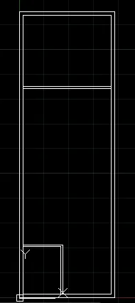
Select line tool from ribbon tab.
Specify the starting point as (15'7.5",59'7.5") in the commaand prompt.
Specify the next point as (@0,-6') in the command prompt and press enter.
Specify the next point as (@6',0) in the command prompt and press enter.
Press esc.
Type "offset" in the command prompt and press enter.
Specify the offset distance as 4.5" and press enter.
Select the previously created lines to offset.
Press esc.
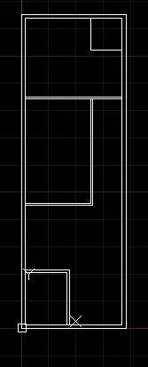
Select line tool from ribbon tab.
Specify the starting point as (4.5",29'1.5") in the commaand prompt.
Specify the next point as (@0,6') in the command prompt and press enter.
Specify the next point as (@7',0) in the command prompt and press enter.
Specify the next point as (@0,-6') in the command prompt and press enter.
Press esc.
Type "offset" in the command prompt and press enter.
Specify the offset distance as 4.5" and press enter.
Select the previously created lines to offset.
Press esc.
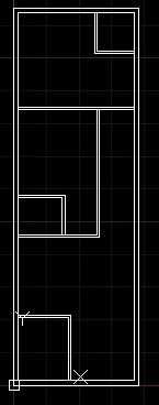
Select line tool from ribbon tab.
Specify the starting point as (19'7.5",0) in the command prompt and press enter.
Specify the next point as (@0,10') in the command prompt and press enter.
Specify the next point as (@3',0) in the command prompt and press enter.
Specify the next point as (@0,-7') in the command prompt and press enter.'
Press esc
Type "offset" in the command prompt and press enter.
Specify the offset distance as 3" and press enter.
Select the previously created lines to offset.
Press esc.
Type "offset" in the command prompt and press enter.
Specify the offset distance as 1' and press enter.
Select the previously created 3' line to offset.
Repeat the offset 10 times for previously offsetted line .
Press esc.
Select the created objects using cursor.
Type "copy" in the command prompt and press enter.
Select the suitable base point and press enter.
Place the copied object to the left.
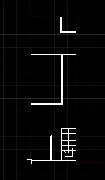
Select line tool from ribbon tab.
Draw a line of length 2'4" and press esc.
Type offset in the command prompt and press enter.
Specify the offset distance as 2.5" and press enter.
Select the previously created line to offset.
Select text tool from ribbon tab.
From the drop down, select single line text.
Place the cursor where the text has to start.
Enter the angle as zero.
Type the required text.
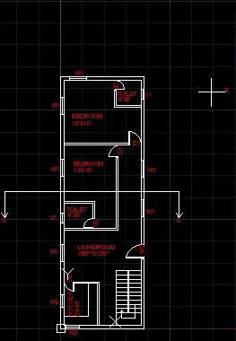
3D Modelling:
Right click in the workspace.
Click on options and select display.
Select color and choose white as color.
Select Apply and close option.
Type viewports in the command prompt and press enter.
Select "Two: Vertical" and press ok.
Select Extrude command from ribbon tab.
Select the exterior walls to extrude.
Select the extrude height as 10' and press enter.
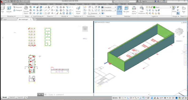
Select the "Model views" as "SE Isometric".
Select the "Model styles" as 2D Wireframe".
In the Plan view create rectangle in the Window and door areas using reactangle tool.
In the 3D view, Selec all the window and door portions.
Select Presspull tool from ribbon tab.
Enetr the required height.
Now select the a single window.
Type Move in the command prompt and press enter.
Select the distance upto Sill level.
Select the Substract tool from ribbon tab and press enter.
Select the wall, hold spacebar and select the window portion.
Press enter to subtract.
Similarly follow the same procedure for all windows
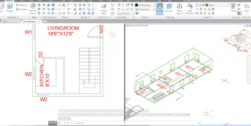
In the 3D View select the view styles as Conceptual.
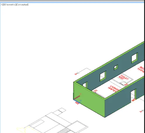
Type 3D Face in the command prompt and press enter.
Select the corners based on which the face has to be created.
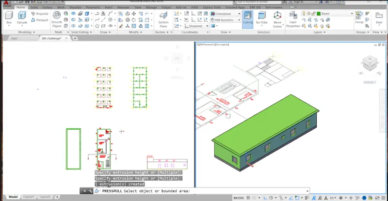
Select visualize from the ribbon tab.
Select Material browser and select the material from the material window.
Type the required material and drag the material to place it in the required place.
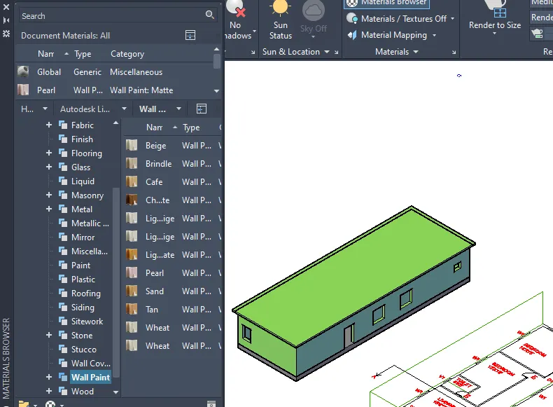
Selct visualize from the ribbon tab.
Select "render to size" and select the required size or select render > viewport or window.
Click on render option to display the rendered image