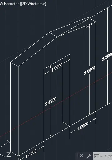
Creating a Floor plan, Footing detail and Isometric view using AutoCad
Q1.
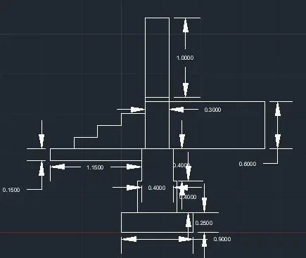
Aim: To create cross section of load bearing wall over spread footing.
Procedure:
Step 1:
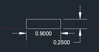
Select rectrangle tool from the ribbon tab.
Specify the first point as (10,0) in the command prompt and press enter.
Select "dimensions" from the command prompt.
Enter the lenght as 0.9 and press enter.
Enter the height as 0.25 and press enter.
Press "esc" to finish
Step 2:
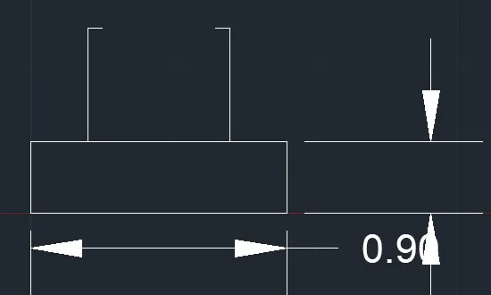
Use line command and draw a line of lenght 0.4 from left top corner.
Type "offset" in the command prompt and select erase.
Select "yes" to erase the source object after offset.
Enter the offset distance as 0.2.
Keep the pointer in the right side and click so that the line gets offsetted.
Keep the pointer on the end point and draw line (using line command) for a distance of 0.1 to the right.
Type "offset" in the command prompt and select erase.
Select "No" to 'erase the source object' after offset.
Enter the offset distance as 0.5.
Keep the pointer in the right side and click so that the line gets offsetted.
Keep the pointer on the end point and draw line (using line command) for a distance of 0.1 to the left.
Step 3:
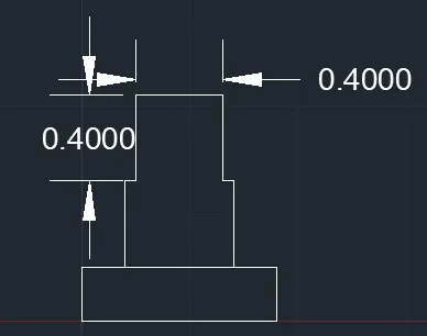
Using "line" command draw a line of length 0.4 in the positive Y direction.
Using "offset" command offset the line to a distance of 0.4
Then draw a line of length of 0.4 in positive X direction.
Step 4:
From the previous point, using line command draw a line of length in 0.6 in positive Y direction.
Type "offset" in the command prompt and press enter.
Select "erase" and then further select "yes" to erase the source object.
Enter the offset distance as "0.3" and and select the object ot offset.
Keep the cursor to the right and click.
Using line command join the lines.
Use "offset" command ,select "erase" and select "No".
Enter the offset distance as 0.05 and select the last drawn line.
Keep the cursor in upward direction and click.
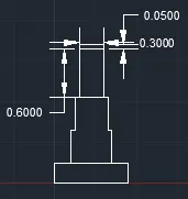
Step 5:
After step 3, select the end point and drawn a line of 1.15 using "line" command.
Using line command, draw line of 0.6 length and draw a line of 1.15 in the negative X direction.
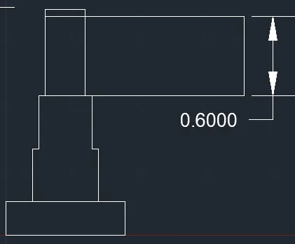
Step 6:
From the end point of line from Step 4 drawn a line of length 1 units in positive Y direction.
Draw the next line of length in 0.3 units in negative X direction.
Draw the next line of length in 1unit in negative Y direction.
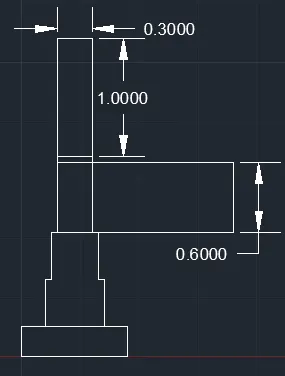
Step 7:
From step 3, select the end point of left vertical line whose length is 0.4 units.
Use line command from the ribbon tab.
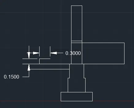
Draw a line of 1.15 unit in negative X direction and specify the next point in negative Y direction with length as 0.15 units.
Specify the next point in positive X direction with length as 1.15.
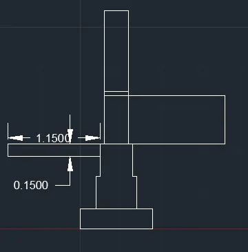
Step 8:
From the left top corner drawn line of length 0.15 in upwrard direction.
Use "offset" command and specify offset distance as 0.3 units.
Select the object to be offsetted and keep the cursor in right side direction.
From the previously offsetted line draw a line of length 0.3 in horizontal direction.
Step 9:
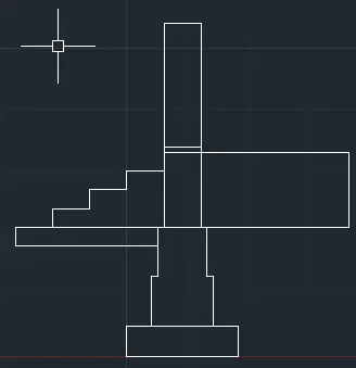
Select the previous drawn lines form step 9.
Type "copy" in the command prompt.
Select the base point and click on the end point of 0.3 units lines. Repeat the same for 2times with same base point but click on the end point previous line to paste.
Output:
Q2.
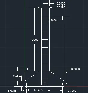
Aim: To create cross section of isolated footing.
Procedure:
Step 1:
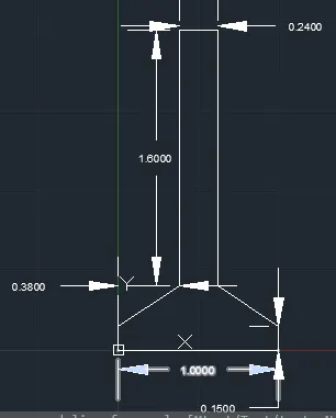
Select line command from the ribbon tab and specify the starting point as (0,0)
Specify the next point as (@1,0) in the command prompt and press enter.
Specify the next point as (@0,0.15) in the command prompt and press enter.
Specify the next point as (@-0.38,0.25) in the command prompt and press enter.
Specify the next point as (@0,1.60) in the command prompt and press enter.
Specify the next point as (@-0.24,0) in the command prompt and press enter.
Specify the next point as (@0,-1.60) in the command prompt and press enter.
Specify the next point as (@0.38-0.25) in the command prompt and press enter.
Specify the next point as (@0,-0.15) in the command prompt and press enter.
Press "esc".
Step 2:
Select line command from the ribbon tab and specify the starting point as (0,0)
Specify the next point as (@0.04,0.09) in the command prompt and press enter.
Specify the next point as (@0,-0.05) in the command prompt and press enter.
Specify the next point as (@0.38,0) in the command prompt and press enter.
Specify the next point as (@0,0.36) in the command prompt and press enter.
Specify the next point as (@0,1.60) in the command prompt and press enter.
Select line command from the ribbon tab and specify the starting point as (0,0)
Specify the next point as (@1.96,0.09) in the command prompt and press enter.
Specify the next point as (@0,-0.05) in the command prompt and press enter.
Specify the next point as (@-0.38,0) in the command prompt and press enter.
Specify the next point as (@0,0.36) in the command prompt and press enter.
Specify the next point as (@0,1.60) in the command prompt and press enter.
Press "esc".
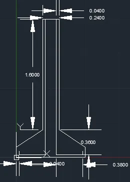
Step 3:
Select line command from the ribbon tab and specify the starting point as (0,0)
Specify the next point as (0.42,0.40) in the command prompt and press enter.
Specify the next point as (@0.16,0) in the command prompt and press enter.
Type "offset" in the command prompt and type the offset distance as 0.20.
Select the object (previously created line) and place the cursor in vertical direction.
Repeat the offset for 8times in vertical direction.
Q3:
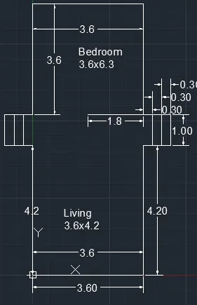
Aim: To create line diagram for 2 bedroom building.
Procedure:
Step 1:
Select line tool from ribbon tab.
Enter the first point as (0,0) in the command prompt and press enter.
Specify the next point as (@3.60,0) in the command prompt and press enter.
Specify the next point as (@0,4.20) in the command prompt and press enter.
Specify the next point as (@3.60,0) in the command prompt and press enter.
Specify the next point as (@0.3,0) in the command prompt and press enter.
Specify the next point as (@0.3,0) in the command prompt and press enter.
Specify the next point as (@0.3,0) in the command prompt and press enter.
Specify the next point as (@0,1) in the command prompt and press enter.
Specify the next point as (@-0.3,0) in the command prompt and press enter.
Specify the next point as (@-0.3,0) in the command prompt and press enter.
Specify the next point as (@-0.3,0) in the command prompt and press enter.
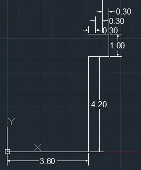
Step 2:
Type "O" enter to activate offset command.
Enter the offset distance as 0.3
Select the 1unit line and offset in negative X direction. Repeat the offset distance of 0.3 in same negative X direction for another time.
Draw a line of length of 1.8 in the negative X direction.
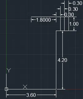
Step 3:
Select line tool from ribbon tab and select the starting point of 1.8 unit line.
Enter the length as 3.6 and click in positive Y direction.
Enter the length as 3.6 and click in negative X direction.
Enter the length as 3.6 and click in negative Y direction.
Press "esc"
Type "O" enter to activate offset command.
Enter the offset distance as 0.3.
Select the 1unit line and offset in negative X direction. Repeat the offset distance of 0.3 in same negative X direction for another time.
Draw a line of length of 1.8 in the negative X direction.
Select line tool from ribbon tab and select the starting point of 1.8 unit line.
Enter the length as 4.2 and click in negative Y direction.
Q4:
Aim: To draw the cross section of load bearing wall showing foundation details using AutoCAD.
Procedure:
Step 1
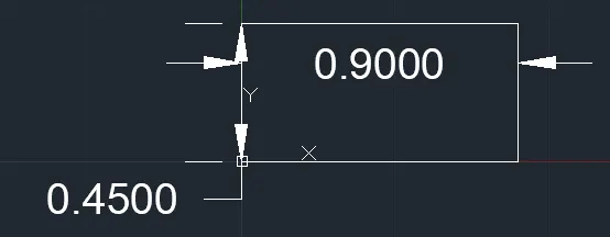
Select "rectangle" tool from ribbon tab.
Specify the starting point as (0,0) in the command prompt and press enter.
Select "dimension from the command prompt.
Enter the length as "0.9" and press enter.
Enter the width as "0.45" and press enter.
Step 2:
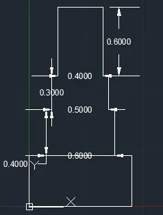
Select the line tool from ribbon command.
Specify the starting point as (0.15,0.45) in the command prompt and press enter.
Specify the next point as (@0,0.40) in the command prompt and press enter.
Specify the next point as (@0.05,0) in the command prompt and press enter.
Specify the next point as (@0,0.30) in the command prompt and press enter.
Specify the next point as (@0.05,0) in the command prompt and press enter.
Specify the next point as (@0,0.60) in the command prompt and press enter.
Specify the next point as (@0.40,0) in the command prompt and press enter.
Specify the next point as (@0,-0.60) in the command prompt and press enter.
Specify the next point as (@0.05,0) in the command prompt and press enter.
Specify the next point as (@0,-0.30) in the command prompt and press enter.
Specify the next point as (@0.05,0) in the command prompt and press enter.
Specify the next point as (@0,-0.40) in the command prompt and press enter.
Step 3:
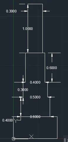
Select the line tool from ribbon command.
Specify the starting point as (0.3,1.75) in the command prompt and press enter.
Specify the next point as (@0,1) in the command prompt and press enter.
Specify the next point as (@0.3,0) in the command prompt and press enter.
Specify the next point as (@0,1) in the command prompt and press enter.
Q5:
Aim: To draw the isometric view of steps.
Procedure:
Step 1:
In the workspace, click on view controls icon in the left top corner.
Select "SW isometric" from the view control.
Select line tool from the ribbon tab.
Click on any point and enter the length as 1 keeping the cursor in negative Y direction.
Enter the length as 0.15 and click keeping the cursor in Z direction.
Enter the length as 1 and click keeping the cursor in Y direction.
Enter the length as 0.15 and click keeping the cursor in negative Z direction.
Press "esc".
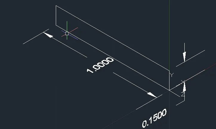
Step 2:
Again click on line tool from the ribbon tab.
Click on the end point of 0.15 unit line present in the negative Y direction.
Enter the length as 0.3 and click on the cursor keeping in X direction.
Enter the length as 1 and click keeping the cursor in Y direction.
Enter the length as 0.3 and click on the cursor keeping in negative X direction.
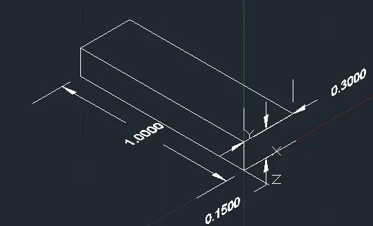
Step 3:
Select the objects created in previous steps, type "COPY" and press enter.
Select the base point and copy the object in corresponding Y direction.
Repeat the copy command until 5steps are created.
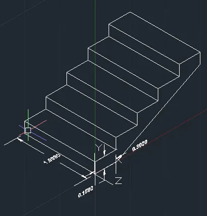
Q6:
Aim: To draw the isometric view of gable wall using AutoCAD.
Procedure:
Procedure:
Step 1:
In the workspace, click on view controls icon in the left top corner.
Select "SW isometric" from the view control.
Select line tool from the ribbon tab.
Click on any point and enter the length as 1 keeping the cursor in Y direction.
Enter the length as 2.42 and click keeping the cursor in Y direction.
Enter the length as 1 and click keeping the cursor in X direction.
Enter the length as 2.42 and click keeping the cursor in negative Y direction.
Enter the length as 0.3 and click keeping the cursor in negative Z direction.
Press "esc".
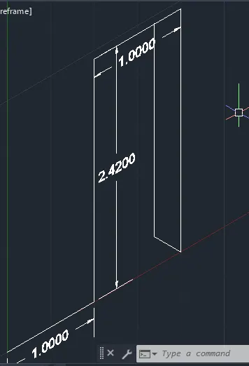
Step 2:
Select line tool from the ribbon tab.
Click on any point and enter the length as 1 keeping the cursor in X direction.
Enter the length as 3 and click keeping the cursor in Y direction.
Draw line of length of 0.83 unit length from the midpoint of door panel connecting previous line.
From the origin draw a line using line tool.
Enter the length as 3 and click keeping the cursor in Y direction.
Draw and join the line to the midpoint using line command.
Press "esc".
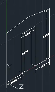
Step 3:
Select line tool from the ribbon tab.
From the origin draw a line using line tool.
Click on any point and enter the length as 0.3 keeping the cursor in negative Z direction.
Enter the length as 3 and click keeping the cursor in Y direction.
Enter the length as 1.5 and click keeping the cursor in X direction.
Enter the length as 1.5 and click keeping the cursor in X direction.
Press "esc".
Draw a line of length 0.3unit joining midpoint of corner points using line command.
Press "esc".