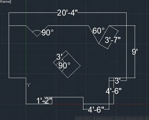
Drafting of various geometries using Chamfer, Fillet tool in AutoCad
Q1
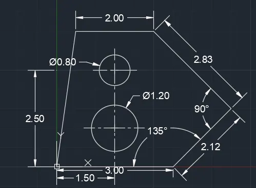
Aim :To draw the given figure using decimal units.
Procedure:
Step1:
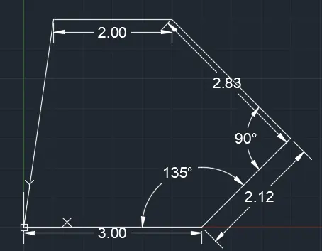
Select the line command from the ribbon tab.
Specify the Starting point as (0,0) in the command prompt and press enter.
Specify the next point as (@3,0) in the command prompt and press enter.
Specify the next point as (@2.12<45) in the command prompt and press enter.
Specify the next point as (@2.83<135) in the command prompt and press enter.
Specify the next point as (@-2,0) in the command prompt and press enter.
Click on the "close" option from the command prompt.
Step 2:
Select circle tool from ribbon tab.
Select "Center, diameter" from the drop-down.
Enter the center point as (1.5,1) and press enter.
Specify the diameter as "1.2" and press "Esc".
Again select the circle tool from the ribbon tab.
Select "Center, diameter" from the drop-down.
Enter the center point as (1.5,2.5) and press enter.
Specify the diameter as "0.8" and press "Esc".
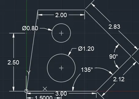
Output:
Q2
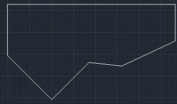
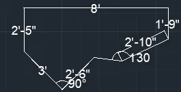
Aim: To draw the given figure using architectural units units.
Procedure:
Step 1:
Type "UNITS" in the command prompt and press enter.
Select the "type" as architectural.
Keep the units as "feet" and press enter.
Select the line tool from the ribbon tab.
Specify the starting point as (0,0) in the command prompt and press enter.
Specify the starting point as (@3'<135) in the command prompt and press enter.
Specify the starting point as (@2'5"<90) in the command prompt and press enter.
Specify the starting point as (@8'<0) in the command prompt and press enter.
Specify the starting point as (@1'9"<90) in the command prompt and press enter.
Specify the starting point as (@2'10"<225) in the command prompt and press enter.
Press "esc".
Select the line tool from the ribbon tab.
Specify the starting point as (0,0) in the command prompt and press enter.
Specify the starting point as (@2'6"<45) in the command prompt and press enter.
From the previous point draw a line connecting the 135degree line.
Press "esc"
Specify the starting point as (@2'5"<90) in the command prompt and press enter.
Step 2:
Type "dimstyle" in the command prompt and press enter.
From the "Modify dimension style" tab, select "primary units".
Select the unit format as "Architectural" and click ok.
Select dimension tool from ribbon tab.
Specify the first point and second point to measure the dimension.
Repeat the dimension tool for measuring all the lines.
Type "DIMANGULAR" in the command prompt and type enter.
Select the two lines between which angle has to be known.
Q3:
Aim: To draw the given image using architectural units in AutoCAD.
Procedure:
Step 1:
Type "UNITS" in the command prompt and press enter.
Select the "type" as engineering.
Keep the units as "feet" and press enter.
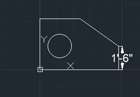
Select the line tool from the ribbon tab.
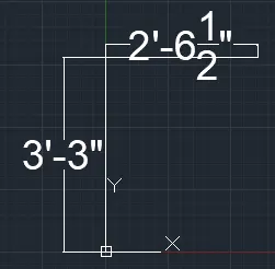
Specify the starting point as (0,0) in the command prompt and press enter.
Specify the starting point as (@3'3"<90) in the command prompt and press enter.
Press "esc".
Step 2:
Select the line tool from the ribbon tab.
Specify the starting point as (0,0) in the command prompt and press enter.
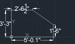
Specify the starting point as (@5'0.1"<0) in the command prompt and press enter.
Specify the starting point as (@1'6"90) in the command prompt and press enter.
Draw a line connecting endpoint of previous line to the endpoint of line whose length is 2'6.5"
Press "esc".
Step 3:
Select "circle" tool from ribbon tab.
From the drop down list select "Centre,diameter".
Specify the centre point as (1'3",1'6") and press enter.
Now specify the diameter as 1'6" and press enter.
Step 4:
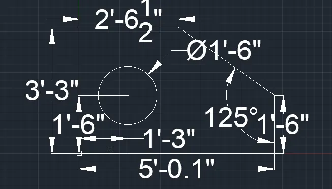
Type "dimstyle" in the command prompt and press enter.
From the "Modify dimension style" tab, select "primary units".
Select the unit format as "Engineering" and click ok.
Select dimension tool from ribbon tab.
Specify the first point and second point to measure the dimension.
Repeat the dimension tool for measuring all the lines.
Type "DIMANGULAR" in the command prompt and type enter.
Select the two lines between which angle has to be known.
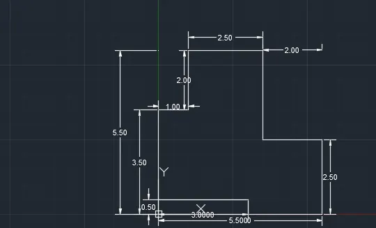
Q4
Aim: To draw the given image using AutoCAD.
Procedure:
Step 1:
Type "UNITS" in the command prompt and press enter.
Select the "type" as engineering.
Keep the units as "Meter" and press enter.
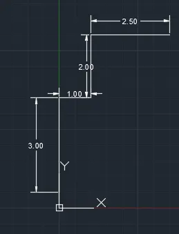
Select the line tool from the ribbon tab.
Specify the starting point as (0,0.5) in the command prompt and press enter.
Specify the starting point as (@0,3) in the command prompt and press enter.
Specify the starting point as (@1,0) in the command prompt and press enter.
Specify the starting point as (@0,2) in the command prompt and press enter.
Step 2:
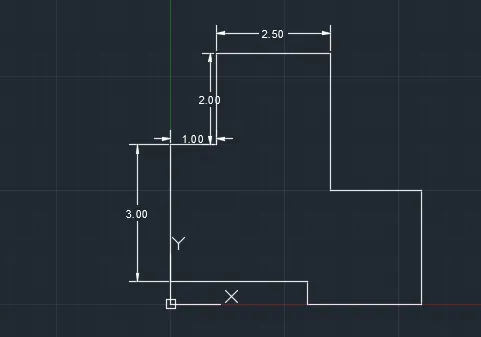
Specify the starting point as (@0,-3) in the command prompt and press enter.
Specify the starting point as (@2,0) in the command prompt and press enter.
Specify the starting point as (@0,-2.5) in the command prompt and press enter.
Specify the starting point as (@-2.5,0) in the command prompt and press enter.
Specify the starting point as (@0,0.5) in the command prompt and press enter.
Specify the starting point as (@-3,0) in the command prompt and press enter.
Step 3:
Type "dimstyle" in the command prompt and press enter.
From the "Modify dimension style" tab, select "primary units".
Select the unit format as "Engineering" and click ok.
Select dimension tool from ribbon tab.
Specify the first point and second point to measure the dimension.
Repeat the dimension tool for measuring all the lines.
Type "DIMANGULAR" in the command prompt and type enter.
Select the two lines between which angle has to be known.
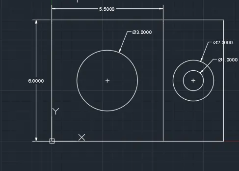
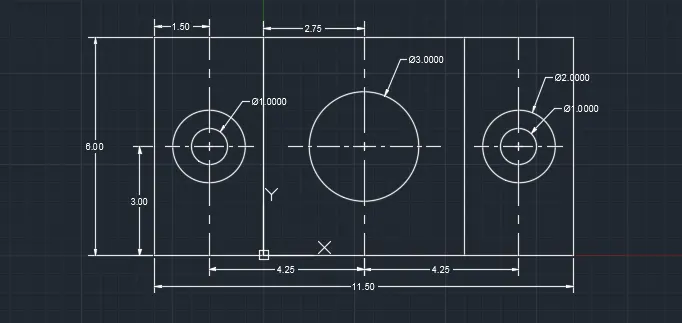
Q5:
Aim: To draw the given figure using AutoCAD
Procedure:
Step 1:
Type "UNITS" in the command prompt and press enter.
Select the "type" as engineering.
Keep the units as "Meter" and press enter.
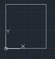
Select the line tool from the ribbon tab.
Specify the starting point as (0,0) in the command prompt and press enter.
Specify the starting point as (@0,6) in the command prompt and press enter.
Specify the starting point as (@5.5,0) in the command prompt and press enter.
Specify the starting point as (@0,-6) in the command prompt and press enter.
Click "Close" in the command prompt.
Step 2:
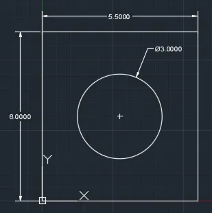
Select the "circle" tool from the ribbon tab.
From the drop-down list select "Centre, diameter".
Specify the center point as (2.75, 3) and press enter.
Now specify the diameter as 3 and press enter.
Step 3:
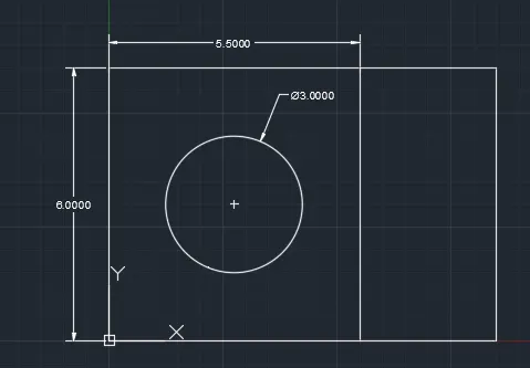
Select the line tool from the ribbon tab.
Specify the starting point as (5.5,0) in the command prompt and press enter.
Specify the starting point as (@3,0) in the command prompt and press enter.
Specify the starting point as (@0,6) in the command prompt and press enter.
Specify the starting point as (@3,0) in the command prompt and press enter.
Press "Esc".
Step 4:
Select the "circle" tool from the ribbon tab.
From the drop-down list select "Centre, diameter".
Specify the center point as (10, 3) and press enter.
Now specify the diameter as 2 and press enter.
Again select the "circle" tool from the ribbon tab.
From the drop-down list select "Centre, diameter".
Specify the center point as (10, 3) and press enter.
Now specify the diameter as 1 and press enter.
Step 5:
Now select the objects created in step 3 and step 4.
Type "Copy" and press enter.
Select the endpoint i.e, (8.5,3) as a base point.
Now move the basepoint of the selected object to the origin and click.
Type "dimstyle" in the command prompt and press enter.
From the "Modify dimension style" tab, select "primary units".
Select the unit format as "Engineering" and click ok.
Select dimension tool from ribbon tab.
Specify the first point and second point to measure the dimension.
Repeat the dimension tool for measuring all the lines.
Type "DIMANGULAR" in the command prompt and type enter.
Select the two lines between which angle has to be known.
Q6:
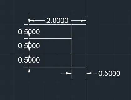
Aim: To draw the given figure using autocad.
Procedure:
Step 1:
Type "UNITS" in the command prompt and press enter.
Select the "type" as engineering.
Keep the units as "Meter" and press enter.
Select the line tool from the ribbon tab.
Specify the starting point as (8,4.5) in the command prompt and press enter.
Specify the starting point as (@1.5,0) in the command prompt and press enter.
Specify the starting point as (@0.5,0) in the command prompt and press enter.
Press "Esc".
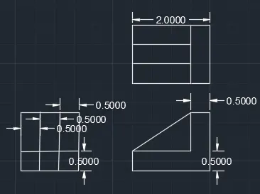
Type "o" enter to activate offset command.
Enter the offset distance as 0.5.
Select the previously created line and offset the line 2 times in positive Y direction.
Join all the endpoints using the line tool from the ribbon tab.
Again use the offset command to offset the right vertical line for a distance of 0.5 in the right side.
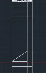
Step 2:
Type "XL" in the command prompt and press enter.
Xl line is activated.
Type "V" and press enter, so that vertical lines are activated.
Place the xl line over the vertical lines available in the workspace.
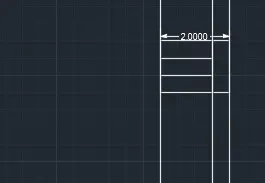
Use line tool from ribbon tab.
As per the question draw using line command over the XL lines.
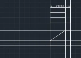
Step 3:
Type "XL" in the command prompt and press enter.
Xl line is activated.
Type "H" and press enter, so that vertical lines are activated.
Place the xl line over the horizontal lines available from step 2.
Use line tool from ribbon tab.
As per the question draw using line command over the XL lines.
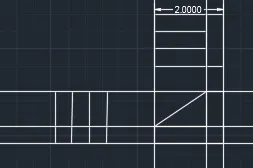
Delete the XL lines after drawing.
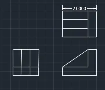
Step 4:
Type "dimstyle" in the command prompt and press enter.
From the "Modify dimension style" tab, select "primary units".
Select the unit format as "Engineering" and click ok.
Select dimension tool from ribbon tab.
Specify the first point and second point to measure the dimension.
Repeat the dimension tool for measuring all the lines.
Type "DIMANGULAR" in the command prompt and type enter.
Select the two lines between which angle has to be known.
Q7
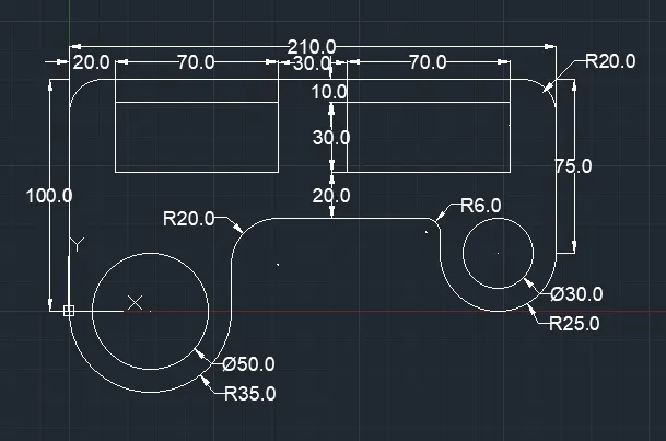
Aim: To draw the given figure in Engineering units using AutoCAD
Procedure:
Type "UNITS" in the command prompt and press enter.
Select the "type" as engineering.
Keep the units as "Meter" and press enter.
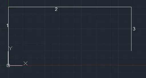
Select the line tool from the ribbon tab.
Specify the starting point as (0,0) in the command prompt and press enter.
Specify the starting point as (@0,100) in the command prompt and press enter.
Specify the starting point as (@210,0) in the command prompt and press enter.
Specify the starting point as (@0,75) in the command prompt and press enter.
Press "Esc".
Step 2:
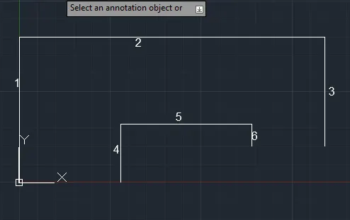
Select the line tool from the ribbon tab.
Specify the starting point as (70,0) in the command prompt and press enter.
Specify the starting point as (@0,40) in the command prompt and press enter.
Specify the starting point as (@90,0) in the command prompt and press enter.
Specify the starting point as (@0,-15) in the command prompt and press enter.
Press "esc"
Step 3:
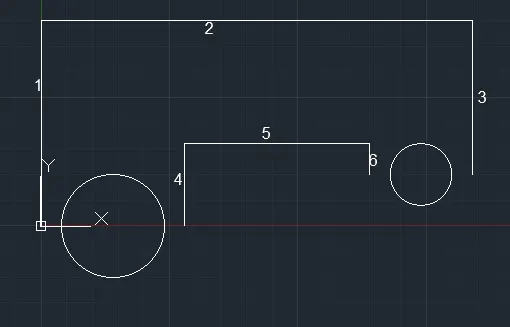
Select the "circle" tool from the ribbon tab.
From the drop-down list select "Centre, diameter".
Specify the center point as (35, 0) and press enter.
Now specify the diameter as 50 and press enter.
Again select the "circle" tool from the ribbon tab.
From the drop-down list select "Centre, diameter".
Specify the center point as (190, 25) and press enter.
Now specify the diameter as 30 and press enter.
Step 4:
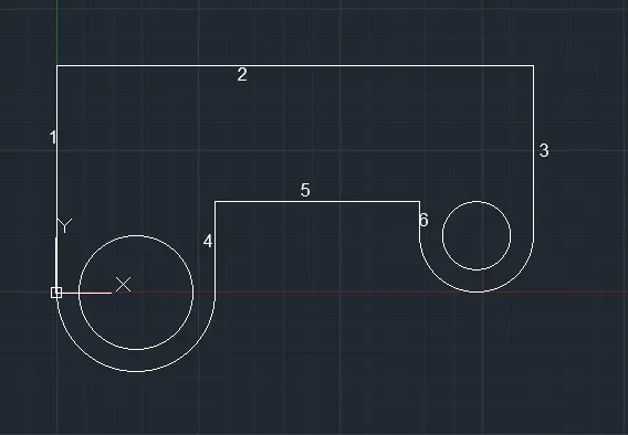
Select "Arc" from the ribbon tab.
From the drop down list select " Start, end, radius".
Specify the start point same as the starting point of line 1.
Specify the end point same as the starting point of line 4.
Enter the radius as "35" in the command prompt.
Type "A" in the command prompt and press enter.
Specify the start point same as the end point of line 6.
Specify the end point same as the end point of line 3.
Enter the radius as "25" in the command prompt.
Step 5:
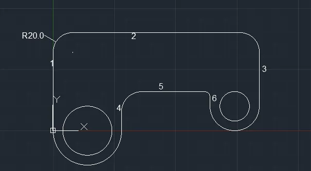
Type "fillet" in the command prompt and press enter.
Select trim `rarr`trim.
Select the line 1 and enter the radius as "15".
Now the select the line 2 to create fillet of radius 15.
Again Type "fillet" in the command prompt and press enter.
Select trim `rarr`trim.
Select the line 1 and enter the radius as "15".
Now the select the line 3 to create fillet of radius 15.
Type "fillet" in the command prompt and press enter.
Select trim `rarr`trim.
Select the line 4 and enter the radius as "20".
Now the select the line 5 to create fillet of radius 20.
Type "fillet" in the command prompt and press enter.
Select trim `rarr`trim.
Select the line 5 and enter the radius as "6".
Now the select the line 6 to create fillet of radius 6.
Step 6:
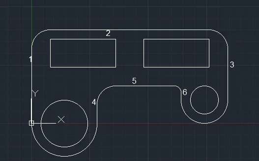
Select rectangle from ribbon tab.
Specify the first corner as (20,60) in the command prompt.
Select dimensions from the command prompt.
Enter the length as 70 and width as 30.
Press "esc".
Again Select rectangle from ribbon tab to create another rectangle.
Specify the first corner as (120,60) in the command prompt.
Select dimensions from the command prompt.
Enter the length as 70 and width as 30.
Step 7:
Type "dimstyle" in the command prompt and press enter.
From the "Modify dimension style" tab, select "primary units".
Select the unit format as "Engineering" and click ok.
Select dimension tool from ribbon tab.
Specify the first point and second point to measure the dimension.
Repeat the dimension tool for measuring all the lines.
Type "DIMANGULAR" in the command prompt and type enter.
Select the two lines between which angle has to be known.
Q8:
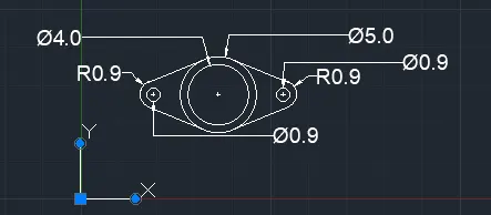
Aim: To draw the given figure using AutoCAD
Procedure:
Step 1:
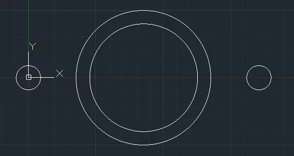
Select the "circle" tool from the ribbon tab.
From the drop-down list select "Centre, diameter".
Specify the center point as (0, 0) and press enter.
Now specify the diameter as 0.9 and press enter.
Again select the "circle" tool from the ribbon tab.
From the drop-down list select "Centre, diameter".
Specify the center point as (4.275, 0) and press enter.
Now specify the diameter as 4 and press enter.
Again select the "circle" tool from the ribbon tab.
From the drop-down list select "Centre, diameter".
Specify the center point as (4.275, 0) and press enter.
Now specify the diameter as 5 and press enter.
Again select the "circle" tool from the ribbon tab.
From the drop-down list select "Centre, diameter".
Specify the center point as (8.55, 0) and press enter.
Now specify the diameter as 0.9 and press enter.
Step 2:
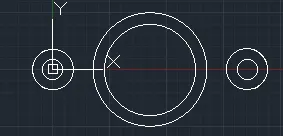
Select the "circle" tool from the ribbon tab.
From the drop-down list select "Centre, radius".
Specify the center point as (0, 0) and press enter.
Now specify the radius as 0.9 and press enter.
Again select the "circle" tool from the ribbon tab.
From the drop-down list select "Centre, radius".
Specify the center point as (8.55, 0) and press enter.
Now specify the radius as 0.9 and press enter.
Step 3:
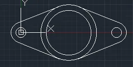
According to the question draw a tangent such that it touches the left and centre circle at only one point.
Repeat the same, by drawing tangent on the other side also.
Q9:
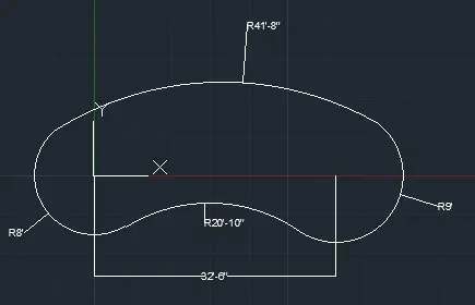
Aim: To draw the given figure using AutoCAD.
Procedure:
Step 1:
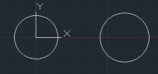
Select the "circle" tool from the ribbon tab.
From the drop-down list select "Centre, radius".
Specify the center point as (0, 0) and press enter.
Now specify the radius as 8' and press enter.
Again select the "circle" tool from the ribbon tab.
From the drop-down list select "Centre, radius".
Specify the center point as (32'6", 0) and press enter.
Now specify the diameter as 9' and press enter.
Step 2:
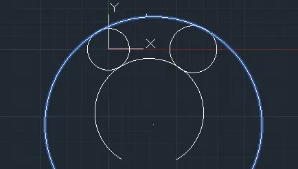
Select "Arc" tool from ribbon tab.
Select " start, end, radius" from the drop down list.
By trail and error method select the start point and end point.
Enter the radius as 41'8" and press ctrl to switch direction.
Select the arc and click on the centre.
Drag down the arc such that it touiches both the circles at top.
Again select "Arc" tool from ribbon tab.
Select " start, end, radius" from the drop down list.
By trail and error method select the start point and end point .
Enter the radius as 20'10" and press ctrl to switch direction.
Select the arc and click on the centre.
Drag down the arc such that it touiches both the circles at top.
Step 3:
Type "dimstyle" in the command prompt and press enter.
From the "Modify dimension style" tab, select "primary units".
Select the unit format as "Architectural" and click ok.
Select dimension tool from ribbon tab.
Specify the first point and second point to measure the dimension.
Repeat the dimension tool for measuring all the lines.
Type "DIMANGULAR" in the command prompt and type enter.
Select the two lines between which angle has to be known.
Q10:
Aim: To draw the given figure using AutoCAD
Procedure:
Step 1:
Type "UNITS" in the command prompt and press enter.
Select the "type" as decimal.
Keep the units as "Meter" and press enter.
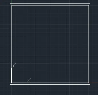
Select the line tool from the ribbon tab.
Select rectangle from ribbon tab.
Specify the first corner as (0,0) in the command prompt.
Select dimensions from the command prompt.
Enter the length as 50 and width as 50.
Press "esc".
Type "offset" in the command prompt and press enter.
Specify the offset distance as 1.5.
Select the rectangle to offset.
Step 2:
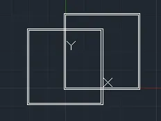
Select the entire object in the workspace.
Type "copy" in the command prompt and press enter.
Select the corner point as base point and press enter.
Move the copy of the object as shown in the image below.
Step 3:
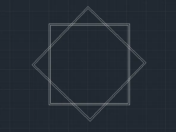
Select the copy of rectangele.
Type "rotate" in the command prompt and press enter.
Select the left corner as base point and rotate to an angle of 45 degree.
Step 4:
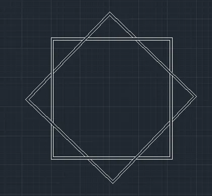
Type "trim" in the command prompt and press enter.
Trim the inner intersection point as per the image given in the question using trim command.
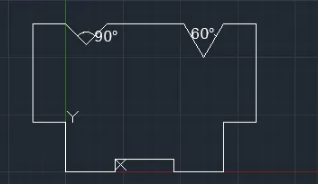
Q11:
Aim: To create the figure using AutoCAD
Procedure:
Step 1:
Type units in the command prompt and press enter.
Select "Architectural" and select "inches".
Press ok.
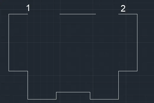
Select line tool from ribbon tab and specify the starting point.
Specify the next point as (@-3',0) in the command prompt and press enter.
Specify the next point as (@0,-6'9") in the command prompt and press enter.
Specify the next point as (@3',0) in the command prompt and press enter.
Specify the next point as (@0,-4'6") in the command prompt and press enter.
Specify the next point as (@4'6",0) in the command prompt and press enter.
Specify the next point as (@0,1'2") in the command prompt and press enter.
Specify the next point as (@5'4",0) in the command prompt and press enter.
Specify the next point as (@0,-1'2") in the command prompt and press enter.
Specify the next point as (@4'6",0) in the command prompt and press enter.
Specify the next point as (@0,4'6") in the command prompt and press enter.
Specify the next point as (@3',0) in the command prompt and press enter.
Specify the next point as (@0,9') in the command prompt and press enter.
Specify the next point as (@-3',0) in the command prompt and press enter.
Step 2:
From the starting point line 1 draw a line using line tool.
Specify the start point as same as that of line 1.
Specify the next point as (@2'8"<315) in the command prompt and press enter.
Specify the next point as (@2'8"<45) in the command prompt and press enter.
Press "esc".
From the starting point line 2 draw a line using line tool.
Specify the start point as same as that of line 1.
Specify the next point as (@3'7"<240) in the command prompt and press enter.
Specify the next point as (@3'7"<120) in the command prompt and press enter.
Press "esc".
Step 3:
Select rectangle tool from command prompt.
Select the first point as (10'2",6'9") in the command prompt and press enter.
Select the dimension option in the command prompt.
Enter the length as 3' and width as 3' in the command prompt.
Select the created rectangle and type "rotate" in the command prompt.
Select bottom corner as base point and rotate the object to 45 degree.